JP2005291606A - Hydrogen gas combustor - Google Patents
Hydrogen gas combustor Download PDFInfo
- Publication number
- JP2005291606A JP2005291606A JP2004106038A JP2004106038A JP2005291606A JP 2005291606 A JP2005291606 A JP 2005291606A JP 2004106038 A JP2004106038 A JP 2004106038A JP 2004106038 A JP2004106038 A JP 2004106038A JP 2005291606 A JP2005291606 A JP 2005291606A
- Authority
- JP
- Japan
- Prior art keywords
- hydrogen gas
- injection nozzle
- combustion
- water
- injected
- Prior art date
- Legal status (The legal status is an assumption and is not a legal conclusion. Google has not performed a legal analysis and makes no representation as to the accuracy of the status listed.)
- Pending
Links
Images
Landscapes
- Combustion Of Fluid Fuel (AREA)
Abstract
Description
本発明は液体化石燃料と水素ガスを同時に燃焼させる水素ガス燃焼機に関する。 The present invention relates to a hydrogen gas combustor that simultaneously burns liquid fossil fuel and hydrogen gas.
一般的に、プラント施設、工場、大型ビル、商業施設では集約した給湯設備を備え、これらの熱源として重油、灯油、ガス等を使用し、灯油ボイラー、ガスボイラー等によって、水を加熱して高温水を発生する構成となっている。
また、温水ボイラーから発生した蒸気は、施設における作業用、加熱用、および一般暖房用など、または、蒸気タービンなどの原動機を動かしたりする動力源としても利用される。
これらボイラーの燃焼方法としては、燃料と空気を異なる噴出口から供給し、燃焼室内で混合させながら燃焼させる拡散燃焼と、燃料と空気を混合させた後燃焼させる予混合燃焼が採用されている。
拡散燃焼では、燃焼室内での燃料と空気が均一に混合されずに、空気比が希薄な領域が必ず存在するため、NOxの低減が一般に困難であるとされる。
一方、予混合燃焼では、燃料と空気が十分に混合されるため、燃焼の反応領域を小さくすることが可能であり、火炎を短くすることができ、また、従来よりも高負荷燃焼できるという利点を有している。そして、燃料稀薄予混合燃焼法を用いることにより、拡散燃焼に比べてNOx排出量が低減されるという利点を有している。
このような、予混合燃焼によりNOxを低減させる燃焼機に関する技術として特開平5−106806号公報記載の技術が知られている。
The steam generated from the hot water boiler is also used as a power source for working in facilities, for heating, for general heating, or for driving a prime mover such as a steam turbine.
As combustion methods of these boilers, diffusion combustion in which fuel and air are supplied from different jet nozzles and burned while being mixed in a combustion chamber, and premixed combustion in which fuel and air are mixed and then burned are employed.
In diffusion combustion, since fuel and air in the combustion chamber are not uniformly mixed and there is always a region where the air ratio is lean, it is generally difficult to reduce NOx.
On the other hand, in the premixed combustion, the fuel and air are sufficiently mixed, so the reaction region of combustion can be reduced, the flame can be shortened, and the combustion can be performed at a higher load than before. have. The use of the fuel lean premixed combustion method has the advantage that the amount of NOx emissions is reduced compared to diffusion combustion.
A technique described in Japanese Patent Application Laid-Open No. 5-106806 is known as a technique related to such a combustor that reduces NOx by premixed combustion.
しかしながら、前記特開平5−106806号公報記載の技術は、ナフサ、ガソリン、灯油、軽油、重油、アルコール等の液体化石燃料のみを使用する構成であるため、排出されるNOxを低減するといっても、そのレベルには限界があり、相当量の濃度のNOxの発生は避けられない。
これらのNOxを完全に排除する燃焼方法として、水素ガスによる燃焼機が開発されているが、水素ガスは点火スピードが速く、火炎が直線的であるので、火炎が局部的に集中し、周囲に熱を伝導させにくく、熱交換性に問題があった。
本発明は係る従来の問題点を解決するためになされたものであって、その目的とするところは、液体化石燃料と水素ガスを同時に燃焼させることによって、NOx、オイル特有の異臭、排煙の発生を防止し、さらに、燃焼熱を効率的に利用する水素ガス燃焼機を提供することにある。
However, since the technology described in Japanese Patent Laid-Open No. 5-106806 is configured to use only liquid fossil fuels such as naphtha, gasoline, kerosene, light oil, heavy oil, alcohol, etc., it can be said that NOx discharged is reduced. The level is limited, and the generation of a considerable amount of NOx is inevitable.
Combustors using hydrogen gas have been developed as a combustion method that completely eliminates these NOx. However, since hydrogen gas has a high ignition speed and the flame is linear, the flame is concentrated locally, It was difficult to conduct heat, and there was a problem in heat exchange.
The present invention has been made to solve the conventional problems, and the object of the present invention is to simultaneously burn liquid fossil fuel and hydrogen gas, thereby reducing NOx, oil-specific odor, and flue gas. An object of the present invention is to provide a hydrogen gas combustor that prevents generation and uses combustion heat efficiently.
請求項1記載の水素ガス燃焼機では、灯油、重油、軽油等の液体化石燃料と空気を混合し、その混合燃料を噴射する液体燃料噴射ノズルと、水素ガスと酸素を混合し、その混合水素ガスを噴射する水素ガス噴射ノズルとを備え、前記液体燃料噴射ノズルからの噴射燃料を燃焼させて火炎を形成し、その火炎に向かって水素ガス噴射ノズルから混合水素ガスを噴射燃焼させる構成とした。
In the hydrogen gas combustor according to
請求項2記載の水素ガス燃焼機では、請求項1記載の水素ガス燃焼機において、燃焼筒を水平方向に配置し、その燃焼筒内に沿って水平に液体燃料噴射ノズルを配置し、その液体燃料噴射ノズルからの噴射燃料に交差するように、前記液体燃料噴射ノズルの上方から斜め下方に向かって混合水素ガスを噴射する構成とした。
The hydrogen gas combustor according to
請求項3記載の水素ガス燃焼機では、請求項1又は2記載の水素ガス燃焼機において、燃焼筒を一連の水タンク内に浸漬した状態で配置し、その燃焼筒を水タンクのやや下側に配置したことを特徴とする。
The hydrogen gas combustor according to
請求項1記載の水素ガス燃焼機においては、液体化石燃料と水素ガスを同時に燃焼させる構成としたので、水素ガスの燃焼が液体化石燃料の燃焼を補助し、不完全燃焼による排気のオイル臭、排煙を低減する。
また、水素ガスの燃焼は直線的であるが、液体化石燃料と共に燃焼させることにより、火炎が燃焼炉内に広がり、炉内全体を加熱し、熱交換性を向上させる。
さらに、水素ガスの燃焼により発生熱量が増大し、水素ガスの爆発力により、火炎長・加熱炉を水平に長く確保して熱交換面積を広く確保することができる。
In the hydrogen gas combustor according to
In addition, the combustion of hydrogen gas is linear, but by burning with liquid fossil fuel, the flame spreads in the combustion furnace, heats the entire furnace, and improves heat exchange.
Furthermore, the amount of generated heat is increased by the combustion of hydrogen gas, and the flame length and the heating furnace can be secured horizontally long by the explosive force of the hydrogen gas, thereby ensuring a wide heat exchange area.
請求項2記載の水素ガス燃焼機においては、燃焼筒及びノズルの向きを水平方向に配置するので、炉内の異物がノズルに詰まるおそれがない。
また、液体燃料噴射ノズルの上方から斜め下方に向かって水素ガスを噴射する構成としたので、水素ガスの燃焼が液体化石燃料の燃焼を補助しながら、それらが協働して燃焼効果を発揮する。
In the hydrogen gas combustor according to the second aspect, since the direction of the combustion cylinder and the nozzle is arranged in the horizontal direction, there is no possibility that foreign matters in the furnace are clogged in the nozzle.
In addition, since the hydrogen gas is injected obliquely downward from above the liquid fuel injection nozzle, the hydrogen gas combustion assists the combustion of the liquid fossil fuel, and they cooperate to exert a combustion effect. .
請求項3記載の水素ガス燃焼機においては、燃焼筒を一連の水タンク内に浸漬した状態で配置したので、燃焼筒の周囲全体の熱を利用して水を加熱することができる。
また、燃焼筒を水タンクのやや下側に配置したので、水タンクの上側に多量の水が配置され、タンクの上から順次高温水を得ることができる。
また、燃焼筒の外側全体が水に接した状態となるので、燃焼炉の過剰燃焼を保護することができる。
In the hydrogen gas combustor according to the third aspect, since the combustion cylinder is disposed in a state of being immersed in a series of water tanks, water can be heated using the heat of the entire periphery of the combustion cylinder.
Further, since the combustion cylinder is disposed slightly below the water tank, a large amount of water is disposed above the water tank, and high-temperature water can be obtained sequentially from the top of the tank.
In addition, since the entire outside of the combustion cylinder is in contact with water, excessive combustion in the combustion furnace can be protected.
以下、図面に基づいて本発明の水素ガス燃焼機を実現する最良の形態を説明する。 Hereinafter, the best mode for realizing the hydrogen gas combustor of the present invention will be described with reference to the drawings.
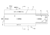
本発明の水素ガス燃焼機は図1、図2に示すように、水平方向に伸びる円筒形の燃焼炉1(燃焼筒)と、燃焼炉1の基端側から挿入された液体燃焼噴射ノズル2と、同じく、燃焼炉1の基端側から挿入されて、燃焼ガス噴射ノズルの上側に並設挿入された水素ガス噴射ノズル3と、燃焼炉1の先端に形成された排気口4と、燃焼炉1を取り巻く水タンク5を主要な構成としている。
As shown in FIGS. 1 and 2, the hydrogen gas combustor of the present invention includes a cylindrical combustion furnace 1 (combustion cylinder) extending in the horizontal direction and a liquid
前記燃焼炉1の基部には一次燃焼室6が配置され、耐火性の砕石とアルミナ質の水硬セメントのような結合剤を混合生成したキャスタブルによって耐熱構造となっている。
一次燃焼室の外側径は420mm、キャスタブルの厚さは約60mm、長さは500mmの形状となっている。
一次燃焼室6に続く二次燃焼室7は内直420mm、長さ1230mmの円筒形の耐熱性金属によって構成されている。この二次燃焼室7の部分は水タンク5内に浸漬した状態で配置されている。
一次燃焼室6ではノズル2,3から噴射される燃料に点火し、二次燃焼室7ではその火炎が広がり、水タンク5が加熱される。
A
The outer diameter of the primary combustion chamber is 420 mm, the castable thickness is about 60 mm, and the length is 500 mm.
The
In the
前記水タンク5は450リットルの水を貯留する容量を備え、タンク上方に注入口8、温度計口9が配置され、タンク下方にドレーン10が配置されている。このタンク5には熱湯が蓄積され、循環装置を経て各所へ配送される。
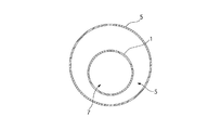
また、水タンクの形状は図2の端面図に示すように、円筒形に形成され、その円筒形のタンク5の内部の下側に燃焼炉1が配置されている。したがって、燃焼炉1の上側の水容量が下側の水容量に比べて多く確保され、水タンク5では主に上側から加熱される。
The
Further, as shown in the end view of FIG. 2, the water tank is formed in a cylindrical shape, and the
前記一次燃焼室6の基部の中央には液体燃料噴射ノズル2が水平に挿入され、そのノズル2からは燃焼炉1の中心へ液体燃料が噴射される。
これらの液体燃料は重油、灯油、軽油等の液体化石燃料を使用することができ、液体燃料を霧状とした後に、空気と混合して、圧力を掛けて噴射する。
A liquid
As these liquid fuels, liquid fossil fuels such as heavy oil, kerosene, and light oil can be used. After the liquid fuel is atomized, it is mixed with air and injected under pressure.
前記水素ガス噴射ノズル3は液体燃料噴射ノズル2の上側から、斜め下方に向かって挿入され、水素ガス噴射ノズル3の噴出口は液体燃料噴射ノズルからの火炎の根元部分に位置している。
水素ガス噴射ノズル3からはブラウンガスが噴射され、液体燃料噴射ノズル3からの噴射火炎に接触して、共に燃焼する。
The hydrogen
Brown gas is injected from the hydrogen
ここで、ブラウンガスとは、水素及び酸素ガスをそのモル比が水素:酸素で2:1となるように均一に混合して得られたガスである。このブラウンガスの燃焼により生じる炎は、その周囲の温度が火炎では2000〜2500℃と非常に高く、これより遠ざかると温度が急激に低くなる性質を有している。また、ブラウンガスは燃焼後には水蒸気となる。 Here, the brown gas is a gas obtained by uniformly mixing hydrogen and oxygen gas so that the molar ratio of hydrogen and oxygen is 2: 1. The flame generated by the combustion of the brown gas has a property that the temperature around it is as high as 2000 to 2500 ° C. in the flame, and the temperature rapidly decreases as the temperature is further away. Brownian gas becomes water vapor after combustion.
次に、本発明の水素ガス燃焼機の作用を説明する。
灯油、重油、軽油等の液体化石燃料を霧化して空気と混合し、圧力を掛けて液体燃料噴射ノズル2から噴射する。噴射すると同時に、点火装置によって火炎を形成する。
次に、水素ガス噴射ノズル3からブラウンガス(水素ガス)を噴射する。この水素ガス噴射ノズル3は液体燃料噴射ノズル2の上から噴射燃料をゆるい角度で横切るように噴射されるので、液体燃料の火炎の噴出し部分に接触して、共に燃焼する。
前記水素ガスは燃焼により高熱を発し、液体燃料の燃焼を補助する。また、水素ガスの燃焼は直線的であるが、液体燃料との接触により、炉内に火炎が広がり、炉に接する水タンクを全体的に加熱する。
Next, the operation of the hydrogen gas combustor of the present invention will be described.
Liquid fossil fuel such as kerosene, heavy oil, and light oil is atomized, mixed with air, and injected from the liquid
Next, brown gas (hydrogen gas) is injected from the hydrogen
The hydrogen gas generates high heat by combustion and assists the combustion of liquid fuel. Moreover, although combustion of hydrogen gas is linear, a flame spreads in a furnace by contact with liquid fuel, and the water tank in contact with the furnace is heated as a whole.
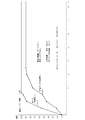
次に、図3は従来例に係る重油を燃料として水タンクを加熱した場合の温度変化をグラフにしたものである。
図3では、ボイラー(0.55tタンク)では、湯温100℃に達するまでに1時間29分を要し、貯湯タンク(0.95tタンク)では、湯温90℃に達するまでに3時間30分を要している。
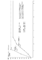
一方、図4は本発明の水素ガス燃焼機による水タンクを加熱した場合の温度変化をグラフにしたものである。
燃料炉及び水タンクの形状その他の条件は図3の燃焼炉と同一のものを使用した。
図4では、ボイラー(0.55tタンク)では、湯温100℃に達するまでに1時間07分を要し、貯湯タンク(0.95tタンク)では、湯温90℃に達するまでに2時間46分を要している。
したがって、図3に比べ、図4の水素ガス燃焼機を使用した場合には、はるかに加熱時間が短縮されたことが確認される。
Next, FIG. 3 is a graph showing changes in temperature when a water tank is heated using heavy oil according to a conventional example as fuel.
In FIG. 3, it takes 1 hour and 29 minutes for the boiler (0.55 t tank) to reach the hot water temperature of 100 ° C., and 3
On the other hand, FIG. 4 is a graph showing the temperature change when the water tank is heated by the hydrogen gas combustor of the present invention.
The shape and other conditions of the fuel furnace and water tank were the same as those of the combustion furnace of FIG.
In FIG. 4, it takes 1 hour 07 minutes for the boiler (0.55 t tank) to reach a hot water temperature of 100 ° C., and 2 hours 46 minutes for the hot water storage tank (0.95 t tank) to reach a hot water temperature of 90 ° C. It takes minutes.
Therefore, compared with FIG. 3, when the hydrogen gas combustor of FIG. 4 is used, it is confirmed that the heating time is much shortened.
次に、図5〜図10は、本発明の水素ガス燃焼機を使用して、灯油のみを使用した場合と、灯油・ブラウンガスを使用した場合の水タンクの温度上昇変化をグラフにしたものである。 Next, FIGS. 5 to 10 are graphs showing changes in the temperature of the water tank when kerosene is used alone and when kerosene / brown gas is used using the hydrogen gas combustor of the present invention. It is.
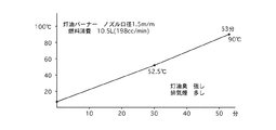
(1)図5(液体燃料噴射ノズルの口径1.5mm 挿入長:100mm)
液体燃料噴射ノズルから灯油を噴射して燃焼させた場合の、タンク内の水の温度上昇変化を示している。タンク内の水が90℃に達するまでに、53分の時間を要している。
消費燃料は10.5リットル(198cc/min)である。
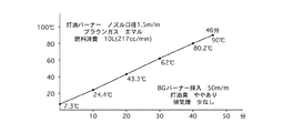
(2)図6(水素ガス噴射ノズル挿入長:50mm)
本発明の水素ガス燃焼機により、液体燃料噴射ノズルから灯油を、水素ガス噴射ノズルからブラウンガスを噴射して燃焼させた場合の、タンク内の水の温度上昇変化を示している。タンク内の水が90℃に達するまでに、46分の時間を要している。
消費燃料は10リットル(217cc/min)である。
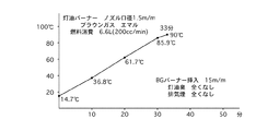
(3)図7(水素ガス噴射ノズル挿入長:15mm)
前記と同様に、液体燃料噴射ノズルから灯油を、水素ガス噴射ノズルからブラウンガスを噴射して燃焼させた場合の、タンク内の水の温度上昇変化を示している。タンク内の水が90℃に達するまでに、33分の時間を要している。実験結果は最良である。
消費燃料は6.6リットル(200cc/min)である。
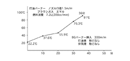
(4)図8(水素ガス噴射ノズル挿入長:300mm)
前記と同様に、液体燃料噴射ノズルから灯油を、水素ガス噴射ノズルからブラウンガスを噴射して燃焼させた場合の、タンク内の水の温度上昇変化を示している。タンク内の水が91℃に達するまでに、36分の時間を要している。
消費燃料は7.2リットル(200cc/min)である。
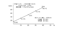
(5)図9(水素ガス噴射ノズル挿入長:150mm)
前記と同様に、液体燃料噴射ノズルから灯油を、水素ガス噴射ノズルからブラウンガスを噴射して燃焼させた場合の、タンク内の水の温度上昇変化を示している。タンク内の水が90.1℃に達するまでに、39分の時間を要している。
消費燃料は7.7リットル(197cc/min)である。
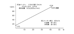
(6)図10(水素ガス噴射ノズル挿入長:80mm)
前記と同様に、液体燃料噴射ノズルから灯油を、水素ガス噴射ノズルからブラウンガスを噴射して燃焼させた場合の、タンク内の水の温度上昇変化を示している。タンク内の水が100℃に達するまでに、41分の時間を要している。
消費燃料は8.3リットル(202cc/min)である。
(1) FIG. 5 (diameter of liquid fuel injection nozzle: 1.5 mm, insertion length: 100 mm)
The temperature rise change of the water in a tank at the time of injecting and burning kerosene from a liquid fuel injection nozzle is shown. It takes 53 minutes for the water in the tank to reach 90 ° C.
The consumed fuel is 10.5 liters (198 cc / min).
(2) FIG. 6 (Hydrogen gas injection nozzle insertion length: 50 mm)
The change in the temperature rise of the water in the tank when kerosene is injected from the liquid fuel injection nozzle and brown gas is injected from the hydrogen gas injection nozzle and burned by the hydrogen gas combustor of the present invention is shown. It takes 46 minutes for the water in the tank to reach 90 ° C.
The consumed fuel is 10 liters (217 cc / min).
(3) FIG. 7 (hydrogen gas injection nozzle insertion length: 15 mm)
Similarly to the above, the temperature rise change of the water in the tank when kerosene is injected from the liquid fuel injection nozzle and Brown gas is injected from the hydrogen gas injection nozzle and burned is shown. It takes 33 minutes for the water in the tank to reach 90 ° C. The experimental results are the best.
The consumed fuel is 6.6 liters (200 cc / min).
(4) FIG. 8 (hydrogen gas injection nozzle insertion length: 300 mm)
Similarly to the above, the temperature rise change of the water in the tank when kerosene is injected from the liquid fuel injection nozzle and Brown gas is injected from the hydrogen gas injection nozzle and burned is shown. It takes 36 minutes for the water in the tank to reach 91 ° C.
The consumed fuel is 7.2 liters (200 cc / min).
(5) FIG. 9 (Hydrogen gas injection nozzle insertion length: 150 mm)
Similarly to the above, the temperature rise change of the water in the tank when kerosene is injected from the liquid fuel injection nozzle and Brown gas is injected from the hydrogen gas injection nozzle and burned is shown. It takes 39 minutes for the water in the tank to reach 90.1 ° C.
The consumed fuel is 7.7 liters (197 cc / min).
(6) FIG. 10 (hydrogen gas injection nozzle insertion length: 80 mm)
Similarly to the above, the temperature rise change of the water in the tank when kerosene is injected from the liquid fuel injection nozzle and Brown gas is injected from the hydrogen gas injection nozzle and burned is shown. It takes 41 minutes for the water in the tank to reach 100 ° C.
The consumed fuel is 8.3 liters (202 cc / min).
前記(1)では排気出口温度が約600℃であるのに対し、(2)の排気出口温度は800℃、(3)〜(6)の排気出口温度は900℃以上であり、排気ガスが完全燃焼してクリーンな排気となっている。
また、(1)に比べて、(2)〜(6)はいずれも沸騰までの時間が短縮され、燃料消費量が低減されている。特に(3)の実験結果が最短時間(33分)で、湯温が90℃に達し、さらに、ブラウンガスの燃料消費量が最も少ないことが確認された。
平均すると、省エネ時間約28%、省エネ燃料は2.9リットルで27%である。これはブラウンガスによって、完全燃焼によるものであり、仮に、灯油ではなく重油を使用した場合には油質から見て、30%以上の省エネとなることは確実である。
総合すると、ブラウンガスの特性から見て、補助燃料として使用した場合が、化石燃料が完全燃焼に近く、クリーンな排気となり、スス(カーボン)が減少し、メンテナンス面からも省エネとなる。
In (1) above, the exhaust outlet temperature is about 600 ° C., whereas the exhaust outlet temperature in (2) is 800 ° C., and the exhaust outlet temperatures in (3) to (6) are 900 ° C. or higher. It is completely burned and clean exhaust.
In addition, as compared with (1), all of (2) to (6) have a shorter time to boiling and fuel consumption is reduced. In particular, it was confirmed that the experimental result of (3) was the shortest time (33 minutes), the hot water temperature reached 90 ° C., and the fuel consumption of Brown gas was the smallest.
On average, energy saving time is about 28%, and energy saving fuel is 2.9 liters and 27%. This is due to the complete combustion of the brown gas. If heavy oil is used instead of kerosene, it is certain that the energy saving is 30% or more in view of oil quality.
Overall, when used as an auxiliary fuel, fossil fuel is almost completely combusted, clean exhaust, soot (carbon) is reduced, and energy is saved from the standpoint of maintenance.
以上、本発明の実施例を説明したが、具体的な構成は前記実施例に限定されるものではなく、発明の要旨を逸脱しない範囲の設計変更等があっても本発明に含まれる。
例えば、液体燃料噴射ノズル及び水素ガス噴射ノズルの形状、挿入位置等については、燃焼炉の機構等に応じて適宜設定を行う。
As mentioned above, although the Example of this invention was described, a concrete structure is not limited to the said Example, Even if there is a design change etc. of the range which does not deviate from the summary of invention, it is contained in this invention.
For example, the shapes and insertion positions of the liquid fuel injection nozzle and the hydrogen gas injection nozzle are appropriately set according to the combustion furnace mechanism and the like.
1 燃焼炉
2 液体燃料噴射ノズル
3 水素ガス噴射ノズル
4 排気口
5 水タンク
6 一次燃焼室
7 二次燃焼室
8 注入口
9 温度計口
10 ドレーン
DESCRIPTION OF
Claims (3)
水素ガスと酸素を混合し、その混合水素ガスを噴射する水素ガス噴射ノズルとを備え、
前記液体燃料噴射ノズルからの噴射燃料を燃焼させて火炎を形成し、その火炎に向かって水素ガス噴射ノズルから混合水素ガスを噴射燃焼させる構成とした水素ガス燃焼機。 Liquid fuel injection nozzle that mixes liquid fossil fuel such as kerosene, heavy oil, light oil and air and injects the mixed fuel;
A hydrogen gas injection nozzle that mixes hydrogen gas and oxygen and injects the mixed hydrogen gas;
A hydrogen gas combustor configured to burn a fuel injected from the liquid fuel injection nozzle to form a flame and to inject and burn mixed hydrogen gas from the hydrogen gas injection nozzle toward the flame.
Priority Applications (1)
| Application Number | Priority Date | Filing Date | Title |
|---|---|---|---|
| JP2004106038A JP2005291606A (en) | 2004-03-31 | 2004-03-31 | Hydrogen gas combustor |
Applications Claiming Priority (1)
| Application Number | Priority Date | Filing Date | Title |
|---|---|---|---|
| JP2004106038A JP2005291606A (en) | 2004-03-31 | 2004-03-31 | Hydrogen gas combustor |
Publications (1)
| Publication Number | Publication Date |
|---|---|
| JP2005291606A true JP2005291606A (en) | 2005-10-20 |
Family
ID=35324728
Family Applications (1)
| Application Number | Title | Priority Date | Filing Date |
|---|---|---|---|
| JP2004106038A Pending JP2005291606A (en) | 2004-03-31 | 2004-03-31 | Hydrogen gas combustor |
Country Status (1)
| Country | Link |
|---|---|
| JP (1) | JP2005291606A (en) |
Cited By (2)
| Publication number | Priority date | Publication date | Assignee | Title |
|---|---|---|---|---|
| KR100833801B1 (en) | 2007-03-09 | 2008-05-30 | 김재화 | Gas & Oil Simultaneous Burner |
| CN111336528A (en) * | 2020-04-13 | 2020-06-26 | 上海甘吉环保科技有限公司 | A method for treating flame-retardant petrochemical residual oil by using Brownian gas to ignite and support combustion |
-
2004
- 2004-03-31 JP JP2004106038A patent/JP2005291606A/en active Pending
Cited By (2)
| Publication number | Priority date | Publication date | Assignee | Title |
|---|---|---|---|---|
| KR100833801B1 (en) | 2007-03-09 | 2008-05-30 | 김재화 | Gas & Oil Simultaneous Burner |
| CN111336528A (en) * | 2020-04-13 | 2020-06-26 | 上海甘吉环保科技有限公司 | A method for treating flame-retardant petrochemical residual oil by using Brownian gas to ignite and support combustion |
Similar Documents
| Publication | Publication Date | Title |
|---|---|---|
| RU2442929C1 (en) | Method of reduction of nitrogen oxides in the boiler working with dispenced carbon where internal combustion type burners are used | |
| KR100765689B1 (en) | Safety burners fueled by wood chips or pellets | |
| KR20100006606A (en) | A coal burner of unnecessary preheating coal dust by combustion method | |
| KR20180107913A (en) | Combustor nozzle | |
| JP2008202902A (en) | Hydrogen and oxygen mixed gas mixed combustion burner | |
| JP2005291606A (en) | Hydrogen gas combustor | |
| JP3878284B2 (en) | Cremation method and apparatus | |
| JP2006118802A (en) | Water heater | |
| KR20240171565A (en) | the eco-friendly low NOx burner structure | |
| CN118922666A (en) | Ammonia combustion furnace | |
| RU2219435C2 (en) | Method of sootless burning of fuel | |
| KR20100137203A (en) | Steam Superheated Water Gas Burners | |
| KR101854568B1 (en) | Solid fuel combustion system | |
| JP6041664B2 (en) | Oil fired boiler and fuel oil atomization method | |
| KR20010019081A (en) | Combustor | |
| KR102836972B1 (en) | Ammonia Complete Combustion System | |
| KR20120007299A (en) | Steam Mixed Water Gas Combustion Burners | |
| KR100725329B1 (en) | Preheating and ignition of fuel combustion device using superheated steam | |
| CN100389286C (en) | A Pulverized Coal Ignition Burner Using Porous Media to Realize Ignition with Minimal Oil | |
| RU58665U1 (en) | CURRENT CAMERA OF THE HEATING DEVICE | |
| JP2008101794A (en) | Hydrogen gas combustor | |
| KR102397601B1 (en) | The pyrolysis steam boiler | |
| KR100313444B1 (en) | A boiler worked by heat generating in the process of dry distillation | |
| JP5187730B2 (en) | Boiler and power generation system | |
| KR100446496B1 (en) | Fireproof construction adhesive to combustion device |
Legal Events
| Date | Code | Title | Description |
|---|---|---|---|
| RD04 | Notification of resignation of power of attorney |
Free format text: JAPANESE INTERMEDIATE CODE: A7424 Effective date: 20051025 |
|
| A621 | Written request for application examination |
Free format text: JAPANESE INTERMEDIATE CODE: A621 Effective date: 20070117 |
|
| A131 | Notification of reasons for refusal |
Free format text: JAPANESE INTERMEDIATE CODE: A131 Effective date: 20090310 |
|
| A02 | Decision of refusal |
Free format text: JAPANESE INTERMEDIATE CODE: A02 Effective date: 20090707 |