JP2005291710A - Reactor body disassembly method - Google Patents
Reactor body disassembly method Download PDFInfo
- Publication number
- JP2005291710A JP2005291710A JP2004102446A JP2004102446A JP2005291710A JP 2005291710 A JP2005291710 A JP 2005291710A JP 2004102446 A JP2004102446 A JP 2004102446A JP 2004102446 A JP2004102446 A JP 2004102446A JP 2005291710 A JP2005291710 A JP 2005291710A
- Authority
- JP
- Japan
- Prior art keywords
- pipe
- tube
- calandria
- pressure
- iron water
- Prior art date
- Legal status (The legal status is an assumption and is not a legal conclusion. Google has not performed a legal analysis and makes no representation as to the accuracy of the status listed.)
- Granted
Links
Images







Landscapes
- Working Measures On Existing Buildindgs (AREA)
Abstract
Description
本発明は、原子炉格納容器内に設置した原子炉本体を解体する方法であって、特に原子炉本体を解体する際に鉄水遮へい体及びカランドリアタンクから圧力管集合体等を先行して取り外すようにした原子炉本体の解体方法に関する。 The present invention is a method for disassembling a reactor main body installed in a reactor containment vessel, and in particular, when dismantling the reactor main body, the pressure water tube assembly and the like from the iron water shielding body and the calandria tank are preceded. The present invention relates to a method for dismantling a reactor main body to be removed.
本発明が実施対象とする原子炉は、例えば図1の重水減速軽水冷却炉などの場合には、生体遮へいコンクリート壁2の内部に鉄水遮へい体3及びカランドリアタンク4で構成した原子炉本体1を設置し、この鉄水遮へい体3はドーナツ状の側部鉄水遮へい体3Aに上部鉄水遮へい体3Bと下部鉄水遮へい体3Cを装着して形成すると共に、鉄水遮へい体3の内部に減速材として重水を充填するカランドリアタンク4を設けている。
For example, in the case of the heavy water moderation light water cooling reactor shown in FIG. 1, the nuclear reactor that is the subject of the present invention is a reactor main body that is composed of an iron
カランドリアタンク4は、側部鉄水遮へい体3Aの内周側に設けた円環状の側壁板4Aと、上部鉄水遮へい体3Bの内側に設けたカランドリアタンク上管板4Bと、下部鉄水遮へい体3Cの内側に設けたカランドリアタンク下管板4Cで外郭を形成すると共に、カランドリアタンク上管板4Bとカランドリアタンク下管板4Cとの間には、所定間隔毎に多数(例えば、200本以上)のカランドリア管4Dと、制御棒を収容する制御棒案内管7を上下に連通する状態で架設している。
The calandria tank 4 includes an annular
カランドリア管4Dには、燃料棒を収容し且つ冷却材である軽水の流路を形成する多数の圧力管5と、圧力管5の上下端部に連結した圧力管延長管6(圧力管上部延長管6A、圧力管下部延長管6B)が装着されており、圧力管5の上部鉄水遮へい体3Bと下部鉄水遮へい体3Cの間には防振板8を設け、これらカランドリア管4D及び圧力管延長管6を含む圧力管5などによって圧力管集合体等9が構成されている。
The
原子炉本体1の解体及び撤去に関しては、例えば特許文献1,2を含む各種の提案が行われており、原子炉格納容器は内部が放射能に汚染されているので作業は外部からの遠隔操作で行われるが、既存の燃料交換装置などを利用して鉄水遮へい体3及びカランドリアタンク4から上下の圧力管延長管6A,6Bを含む圧力管5などを下方へ引き抜き、原子炉格納容器の下側から外部に撤去した後に、カランドリア管4Dを含む残りの原子炉本体1はマニピュレータなどを用いて上部から下部へ順次部材ごとに切断して解体し、原子炉格納容器の上側から外部に撤去するのが一般的であった。
Regarding the dismantling and removal of the reactor
これらの従来技術の場合には、燃料交換装置で圧力管5を引き抜いた後でも、放射能レベルの高いカランドリア管4Dは残されており、このカランドリア管4Dをマニュピュレータによる遠隔操作で切断除去する作業は、長期間を要して経済的な損失を生ずると共に、放射能レベルの高い作業環境で解体作業を継続しなければならないので、安全性を確保するために一層の管理努力やメンテナンスを図る必要がある。
In the case of these prior arts, the Calandria
また、マニュピュレータの遠隔操作でカランドリア管4Dを含む解体及び撤去作業を行う場合、例え監視用カメラでモニターしても、マニュピュレータを操作する3次元的な位置を正確に監視することはきわめて困難であると共に、このマニュピュレータを正確に操作するオペレーターは高度の技能を必要とするので、この技能を習熟するための訓練に長期を必要とし、そのための訓練には時間と経費が必要である。
Also, when dismantling and removing work including the Calandria
さらに、マニュピュレータに切断工具又は把持工具を装着して行う作業は、切断個所に適合させて各種の切断工具を付け替えると共に、切断した後には把持工具に付け替える必要があるので、その段取り作業に多くの時間を必要とし、特に炉心部にあるカランドリア管の解体及び撤去作業は、限られた狭い作業領域で行う必要があるので、作業能率及び安全作業の点でも望ましくないことなどの課題があった。 Furthermore, the work to be performed by attaching a cutting tool or gripping tool to the manipulator is necessary to change various cutting tools according to the cutting location and to replace the gripping tool after cutting. In particular, the disassembly and removal work of the Calandria tube in the core must be performed in a limited and narrow work area, which is problematic in terms of work efficiency and safety work. .
これら従来技術の課題を解決し得る「原子炉の解体及び撤去方法」の提案を、本件出願人は先に特願2002−380667号(先願発明)で行ったが、この提案ではカランドリアタンクの鉄水遮へい体その他の内部配管類と連結している多数の圧力管集合体等(上下の延長管を含む圧力管及びカランドリア管)を、解体して撤去する炉心部(コア部)に対する一次解体及び撤去作業と、残りの鉄水遮へい体その他の内部配管類を備えたカランドリアタンクの外殻を解体して撤去する二次解体及び撤去作業に分けて施工している。 The applicant previously made a proposal of a “reactor dismantling and removal method” that can solve these problems of the prior art in Japanese Patent Application No. 2002-380667 (prior invention). Primary to the core (core part) that dismantles and removes a number of pressure pipe assemblies (pressure pipes including upper and lower extension pipes and calandria pipes) connected to the iron water shielding body and other internal pipes Construction is divided into dismantling and removal work, and secondary dismantling and removal work that dismantles and removes the outer shell of the Calandria tank with the remaining iron water shield and other internal piping.
そして、特に放射能レベルの高いコア部の解体については、先端に中空ビットを装着したコアチューブを備えたコアボーリング装置を原子炉本体の上方に配置し、カランドリア管の外周に嵌入する内径をした中空ビット及びコアチューブによって、各カランドリア管を鉄水遮へい体及びカランドリアタンクの外殻から切断し、圧力管集合体等を原子炉の下方に抜き落として一次解体作業を施工し、その後に圧力管集合体等を除いた比較的放射能レベルの低い外殻部に対し、レーザ切断装置を用いて二次解体作業を施工する。 And for the dismantling of the core part with a particularly high radioactivity level, a core boring device equipped with a core tube with a hollow bit attached to the tip is arranged above the reactor body and has an inner diameter that fits into the outer periphery of the calandria tube Each calandria pipe is cut from the iron water shielding body and the outer shell of the calandria tank with a hollow bit and a core tube, and the pressure pipe assembly etc. is pulled down below the reactor to perform the primary dismantling work. Secondary dismantling work is carried out using a laser cutting device on the outer shell portion with a relatively low radioactivity level excluding tube assemblies and the like.
この先願発明では、一次解体及び撤去作業で圧力管集合体等を除去するので、二次解体及び撤去作業を安全に実施でき且つ安全作業の管理も容易であること、コアボーリング装置はマニピュレータに比べ、製作が容易で且つ安価であると共に、使用実績もあるので信頼性が高くメンテナンスも容易であり、高度な習熟性を必要とせずオペレータに対して長期の訓練を施す必要もなく、切断個所に対して監視による位置決めが容易で且つ操作性も良いので、著しく工期の短縮を図ることが可能であることなど、前記した従来技術の課題を解決し得るものである。 In the prior invention, the pressure pipe assembly and the like are removed by the primary dismantling and removal work, so that the secondary dismantling and removal work can be performed safely and the management of the safe work is easy, and the core boring device is compared with the manipulator. It is easy and inexpensive to manufacture, has a track record of use, is reliable and easy to maintain, does not require high level of proficiency, and does not require long-term training for the operator. On the other hand, since the positioning by monitoring is easy and the operability is good, it is possible to solve the above-mentioned problems of the prior art, such as the remarkable shortening of the construction period.
しかし、圧力管集合体等は様々な連結板及びスリーブを介してカランドリアタンクの上下管板などに連結されているので、先願発明におけるコアボーリング装置を用いた一次解体作業で、圧力管集合体等を一挙に切断して抜き落とすことが必ずしも容易ではないことや、圧力管の外周側からカランドリア管などをコアボーリング装置で切削する際に、圧力管やカランドリア管などを形成するジルコニウム系合金の切削屑や研磨材などの二次廃棄物がカランドリアタンク内に拡散すると、その回収作業が作業能率を低下させ、特に遮へい対策として原子炉本体内に水を充填している場合には回収不能である。 However, since the pressure tube assembly and the like are connected to the upper and lower tube plates of the Calandria tank via various connection plates and sleeves, the pressure tube assembly is used in the primary disassembly work using the core boring device in the prior invention. Zirconium-based alloy that forms a pressure tube, a calandria tube, etc. when it is not always easy to cut and remove the body etc. at once, or when cutting a calandria tube, etc. from the outer periphery of the pressure tube with a core boring device When secondary waste such as cutting scraps and abrasives diffuses into the calandria tank, the recovery operation reduces work efficiency, especially when the reactor body is filled with water as a shielding measure. It is impossible.
また、コア部に対する一次解体作業が原子炉本体の上部側からのみ施工されるので、作業能率をより一層向上させる際に支障となることなど、さらなる改善を必要とする課題が残されていたので、本発明では先願発明を含む従来技術のこれら課題を解決し得る原子炉本体の解体方法を提供するが、特に先願発明の場合と同様に施工される一次解体作業である圧力管集合体等の解体を容易にすること、切削による二次廃棄物を原子炉本体内に拡散させないこと、原子炉本体の上方側と下方側で並行作業が施工できることなどを主たる目的としている。 In addition, since the primary dismantling work for the core part is performed only from the upper side of the reactor main body, there are still issues that require further improvements, such as hindering further improvement of work efficiency. The present invention provides a method for disassembling a reactor main body that can solve these problems of the prior art including the invention of the prior application, and in particular, a pressure tube assembly that is a primary dismantling operation that is performed in the same manner as in the case of the prior application invention. Its main purpose is to facilitate the dismantling of materials, etc., to prevent secondary waste from cutting from diffusing into the reactor body, and to allow parallel work to be performed on the upper and lower sides of the reactor body.
本発明の原子炉本体の解体方法は、カランドリアタンクと上下の鉄水遮へい体に連結したカランドリア管及び圧力管を含む圧力管集合体等を先行解体で取り外す原子炉本体の解体方法であって、原子炉本体の上方に配置したコアボーリング装置による管外切断と、原子炉本体の下方に配置したアブレイシブジェット切断装置による管内切断によって連結個所を切り離し、圧力管集合体等を引き抜いて取り外すようにしている。(請求項1) The reactor body disassembly method of the present invention is a reactor body disassembly method in which a Calandria pipe connected to a Calandria tank and upper and lower iron water shields, a pressure tube assembly including a pressure pipe, and the like are removed by prior disassembly. , Disconnect the connection part by external cutting with a core boring device located above the reactor body and in-tube cutting with an abrasive jet cutting device located below the reactor body, and pull out the pressure tube assembly and remove it I am doing so. (Claim 1)
請求項1の原子炉本体の解体方法において、上部鉄水遮へい体の上端側に連結した上部鉄水遮へい体スリーブの上端側をコアボーリング装置の管外切断で切り離すと共に、カランドリアタンク上管板に連結した上部鉄水遮へい体スリーブ及び、上部鉄水遮へい体スリーブ内の圧力管上部延長管の下端側をアブレイシブジェット切断装置の管内切断で切り離し、カランドリアタンク下管板より上部側の圧力管集合体等を上方へ引き抜く工程と、カランドリアタンク下管板に連結したカランドリア管の下端側をアブレイシブジェット切断装置の管内切断で切り離すと共に、カランドリアタンク上管板に連結したカランドリア管の上端側及び、カランドリア管内で圧力管に連結した圧力管上部延長管の下端側をコアボーリング装置の管外切断で切り離し、カランドリアタンク上管板とカランドリアタンク下管板間の圧力管集合体等を上方へ引き抜く工程と備えている形態を採ることができる。(請求項2)
2. The method for disassembling a reactor main body according to
請求項2の工程に加え、下部鉄水遮へい体管板に連結した下部鉄水遮へい体スリーブの下端側及び、下部鉄水遮へい体スリーブ内の圧力管下部延長管の途中をアブレイシブジェット切断装置の管内切断で切り離し、カランドリアタンク下管板と下部鉄水遮へい体管板間に下部鉄水遮へい体スリーブを残余させた状態で、カランドリアタンク下管板より下部側の圧力管集合体等を下方へ引き抜く工程とを備えている形態を採ることができる。(請求項3)
In addition to the process of
本発明では、先願発明の場合と同様に原子炉本体のなかでも放射能レベルの高い圧力管集合体等を、先行解体である一次解体作業によって取り外した後に、放射能レベルの低い残りの原子炉本体を二次解体作業で分解処理分すようにしているので、安全作業を確保することができると共に、特にカランドリアタンクを形成する上下の鉄水遮へい体から連結強度の高い圧力管集合体等を取り外すことによって、鉄水遮へい体を含む残りの原子炉本体に対する二次解体作業が容易になって、二次解体作業を能率的に行うことができる。 In the present invention, as in the case of the prior application invention, the pressure tube assembly having a high radioactivity level in the reactor main body is removed by the primary dismantling operation, which is a prior dismantling, and then the remaining atoms having a low radioactivity level are remaining. Since the main body of the furnace is disassembled by secondary dismantling work, safety work can be secured, and in particular, a pressure tube assembly with high connection strength from the upper and lower iron water shielding bodies forming the calandria tank Etc. are removed, the secondary dismantling work for the remaining reactor main body including the iron water shielding body is facilitated, and the secondary dismantling work can be performed efficiently.
また、先願発明の場合のように多数の各圧力管集合体等の外周を一挙に切断するのではなく、主要な連結個所を個別に切断するようにしているので、切断作業が容易であると共に、原子炉本体の上方に設置したコアボーリング切断装置による管外からの切断作業と、原子炉本体の下方に設置したアブレイシブジェットによる管内からの切断作業を併用しているので、上方側と下方側で並行作業を行って切削作業及び撤去作業の能率を向上させることができる。 In addition, since the outer periphery of each of the pressure tube assemblies is not cut at once as in the case of the invention of the prior application, the main connecting points are cut individually, so that the cutting work is easy. In addition, since the cutting work from outside the pipe by the core boring cutting device installed above the reactor body and the cutting work from inside the pipe by the abrasive jet installed below the reactor body are used together, The efficiency of the cutting work and the removal work can be improved by performing parallel work on the lower side.
また、コアボーリング装置による管外切断作業及びアブレイシブジェット切断装置による管内切断作業は、各装置を昇降移動させて切断作業を行うことができるので、外部からの位置決め及び遠隔操作が容易であると共に、装置を小型化することが可能であること、これら装置は土木や建築その他の分野での使用実績も多く装置の信頼性が高く且つ作業者は操作に習熟しているので、安全且つ能率的に作業を行うことが可能であること、駆動源は作業領域から離れた位置に設置できるので、原子炉格納容器内の環境で故障することが軽減され、仮に故障した場合でもメンテナンスが容易であること、などが期待できる。 Moreover, since the cutting work outside the pipe by the core boring device and the cutting work inside the tube by the abrasive jet cutting device can be performed by moving each device up and down, positioning from the outside and remote operation are easy. In addition, it is possible to reduce the size of the devices, and these devices are used in civil engineering, construction, and other fields, and the reliability of the devices is high. Because it is possible to perform work in an automated manner and the drive source can be installed at a position away from the work area, it is possible to reduce failures in the environment inside the reactor containment vessel, and even if a failure occurs, maintenance is easy. Something can be expected.
また、アブレイシブジェット切断装置による管内切断作業では、切削によって発生した粉塵や切削水に添加した研磨材などの二次廃棄物を、圧力管集合体等の管内を介して切削水と一緒に外部へ排出することができ、カランドリアタンク内に拡散させることがないので、内部の環境を悪化させることがなく且つカランドリアタンク内での回収作業が不要であること、レーザ切断などのように熱を加えないので、加熱による化学反応で有害ガスを発生することもなく、水中での解体作業にも適合できることなどが期待できる。 Also, in the pipe cutting work by the abrasive jet cutting device, secondary waste such as dust generated by cutting and abrasives added to the cutting water is brought together with the cutting water through the inside of the pipe such as the pressure pipe assembly. Since it can be discharged to the outside and does not diffuse into the calandria tank, the internal environment is not deteriorated and no recovery work is required in the calandria tank, laser cutting, etc. Since no heat is applied, no harmful gas is generated by a chemical reaction caused by heating, and it can be expected to be suitable for dismantling work in water.
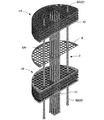
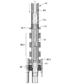
本発明の原子炉本体の解体方法について、実施対象である図1の原子炉本体1及び、本発明を適用した好適な実施形態を示す図2〜15の添付図面に基づき詳細に説明するが、図2は図1の原子炉本体1における炉心部(コア部)の斜視図を示し、図3は図2における圧力管集合体等の縦断面図を示し、図4は圧力管集合体等の解体方法の工程図を示し、図5〜14は各解体工程における詳細説明図を示す。
The method for disassembling the reactor main body of the present invention will be described in detail with reference to the reactor
図2は、原子炉本体1から鉄水遮へい体3における側部鉄水遮へい体3Aと、カランドリアタンク4における側壁板4Aとを省略した炉心部(コア部)を示すが、多数の開口部を所定間隔毎に形成したコア部上層板1Aとコア部下層板1B及び、両者の中間に配置された防振板8とを備え、コア部上層板1Aとコア部下層板1Bの間を連結するカランドリア管4Dを含む多数の圧力管集合体等9が、これらの各開口部に挿通する態様でそれぞれ装着されている。
FIG. 2 shows a core portion (core portion) in which the side iron
圧力管集合体等9は、コア部上層板1Aとコア部下層板1Bを貫通する態様で両者間に装着されたカランドリア管4Dと、カランドリア管4D内に収容した圧力管5と、圧力管5の上端側に連結してコア部上層板1Aの上方へ突出させた圧力管上部延長管6Aと、圧力管5の下端側に連結してコア部下層板1Bの下方へ突出させた圧力管下部延長管6Bと、圧力管上部延長管6Aの外側に配置した上部鉄水遮へい体スリーブ10と、圧力管下部延長管6Bの外側に配置した下部鉄水遮へい体スリーブ11と、圧力管上部延長管6A内に装着した燃料棒収容プラグ12で構成されている。
The
図3では、コア部上層板1Aとコア部下層板1B及び防振板8に対する圧力管集合体等9の連結状態を詳細に示しているが、コア部上層板1Aは図3(a)のように、上部鉄水遮へい体上管板3B−1、3枚の上部鉄水遮へい体遮へい板3B−2と、上部鉄水遮へい体下管板3B−3と、カランドリアタンク上管板4Bとで構成され、コア部下層板1Bは図3(b)のように、カランドリアタンク下管板4Cと、3枚の下部鉄水遮へい体遮へい板3C−1と、下部鉄水遮へい体管板3C−2とで構成されている。
In FIG. 3, the connection state of the
圧力管集合体等9は、コア部上層板1A及びコア部下層板1Bに対して図3で示すように連結されており、図示の実施形態では切断個所を第1〜5の切断個所(イ)〜(ホ)のように設定し、第1の切断個所(イ)では上部鉄水遮へい体上管板3B−1に連結されている上部鉄水遮へい体スリーブ10の上端側を切断し、第2の切断個所(ロ)ではカランドリアタンク上管板4Bに連結されている上部鉄水遮へい体スリーブ10の下端側を切断し、第3の切断個所(ハ)ではカランドリアタンク上管板4Bに連結されているカランドリア管4Dの上端側を切断し、それぞれ切り離すようにしている。
The
また、第4の切断個所(ニ)ではカランドリアタンク下管板4Cに連結されているカランドリア管4Dの下端側を切断し、第5の切断個所(ホ)では下部鉄水遮へい体管板3C−2に連結されている下部鉄水遮へい体スリーブ11の下端側を切断し、それぞれ切り離すようにしており、これらの連結個所を切断することによって、最終的には図15で示すように、原子炉本体1のコア部上層板1A及びコア部下層板1Bから、残存する放射能レベルが最も高い圧力管集合体等9の主要部分を取り外す先行解体(一次解体)作業を行うことができる。
Further, at the fourth cutting point (d), the lower end side of the
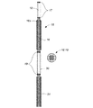
以下では、原子炉本体1の炉心部に設けられたコア部上層板1Aとコア部下層板1Bから圧力管集合体等9を先行解体する手順について、図4の工程図及び図5〜14の詳細説明図に基づき解体の手順を説明すると、まず圧力管5に連結された圧力管下部延長管6Bの下端部内に特殊シールプラグ13が装着されている場合には、図5のように特殊シールプラグ13を引き抜いて取り外し(工程a)、
In the following, with respect to the procedure of preceding dismantling of the
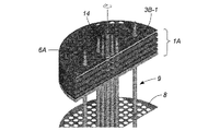
次に、上部鉄水遮へい体スリーブ10の上端側と上部鉄水遮へい体上管板3B−1との連結個所を縁切りするために、第1の切断個所(イ)に対して図6a及び図6bで示すように、圧力管上部延長管6Aの外周に適合する内径を備えたメタルコアボーリング装置14を嵌合させ、回転させながら先端ビット14aで上部鉄水遮へい体上管板3B−1を管外から切断することにより、上部鉄水遮へい体スリーブ10の上端側との切断個所が切り離される(工程b)。
Next, FIG. 6 a and FIG. 6 are taken with respect to the first cutting point (A) in order to cut off the connection portion between the upper end side of the upper iron water shielding
このメタルコアボーリング装置14による連結個所の切断作業は、切断個所が部鉄水遮へい体上管板3B−1に限定されているので切断が容易であり、また圧力管上部延長管6Aを案内部材としてメタルコアボーリング装置14を昇降移動させるので位置決めも容易であり、高度の習熟性を必要としないで能率良く且つ安全に作業を行うことが可能であと共に、先端ビットを交換する程度の改造で既存のメタルコアボーリング装置を利用することが可能であるので、装置を安価に提供することが可能である。
The cutting operation of the connecting portion by the metal core
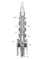
次に、上部鉄水遮へい体スリーブ10の下端側とカランドリアタンク上管板4Bとの連結個所を縁切りするために、第2の切断個所(ロ)に対して図7のようにアブレイシブジェット切断装置15を圧力管下部延長管6B内に挿入すると共に、ジェットノズル15aが切断個所と整合するように設定し、回転又首振り(全体又は、ジェットノズル15aの有る先端部のみ)させながらジェットノズル16aからジェット水流を噴射させ、圧力管上部延長管6A及び上部鉄水遮へい体スリーブ10を管内から切断することにより、上部鉄水遮へい体スリーブ10の下端側との切断個所が切り離される(工程c)。
Next, in order to cut off the connection portion between the lower end side of the upper iron water shielding
アブレイシブジェット切断装置15は、先端側管体16に設けたジェットノズル16aから、基部側管体21を介して外部から供給された超高圧水による切削水に微細砥粒の研磨材を添加して高圧噴射させるが、先端側管体16の前後には図8のように、両端にベアリング機構17,19を装着した管体の外周に拡縮径が可能なエアバッグ装置18,20を設け、外部から供給された空気圧又は水圧でエアバッグ機構18,20を膨張させることによって、アブレイシブジェット切断装置15を圧力管集合体等9の内部に係止保持させる。
The abrasive
このアブレイシブジェット切断装置15による切断作業は、切削屑や添加した研磨材などの二次廃棄物は切削水と一緒に管内を流下して外部に排出されるので、粉塵の発生による作業環境の悪化を防止することができると共に、原子炉本体1内に二次廃棄物が拡散されないので、回収作業による作業能率の低下を防止することが可能であり、またエアバッグ機構18,20によって、切削時にはアブレイシブジェット切断装置15を安定保持し且つ、切削水などが上部側へ跳ね返るのを防止することが可能である。
In the cutting work by this abrasive
以上の工程では、工程bで上部鉄水遮へい体スリーブ10の上端側が上部鉄水遮へい体上管板3B−1から切り離されると共に、工程cで圧力管上部延長管6A及び上部鉄水遮へい体スリーブ10の下端側がカランドリアタンク上管板4Bから切り離されているので、カランドリアタンク上管板4Bより燃料棒収容プラグ12を含む上方の圧力管集合体等9を、コア部上層板1Aから分離して取り外しできる状態になっているので、直ちに取り外し作業を行う実施形態を採ることも可能である。
In the above process, the upper iron water shielding
しかし、図示の実施形態では工程cで圧力管下部延長管6B内に挿入したアブレイシブジェット切断装置15を引き続き活用し、他の連結個所に対する切断作業を行った後に取り外し作業を行う形態を採り、図9のようにアブレイシブジェット切断装置15のジェットノズル15aを、ランドリアタンク下管板4C内に移動して第4の切断個所(ニ)に設定し、、カランドリアタンク下管板4Cに連結されているカランドリア管4Dと圧力管5の下端側を管内から切断して切り離しを行う(工程d)。
However, in the illustrated embodiment, the abrasive
次に、既に工程bで第1の切断個所(イ)を工程cで第2の切断個所(ロ)を切断したコア部上層板1Aに対し、開閉可能なチャック部22を先端に装着した引き抜き作業用装置(全体の図示を省略)を原子炉本体1の上方から吊り降ろし、図10a及び図10bのように圧力管上部延長管6Aの先端側を把持して上方へ引き抜くと、カランドリアタンク上管板4Bより燃料棒収容プラグ12を含む上方の圧力管集合体等9を、コア部上層板1Aから分離して取り外すことができる(工程e)。
Next, the core part
このアブレイシブジェット切断装置15による切断作業は、前記したコア部上層板1Aにおける切断作業の場合と同様に、管内で膨張させたエアバッグ機構18,20によってアブレイシブジェット切断装置15を安定保持させた状態で行われると共に、切断によって切り離された圧力管下部延長管6Bの途中及び下部鉄水遮へい体スリーブ11の下端側は、エアバッグ機構18,20によって落下しないように係止保持されるが、この切断作業においても粉塵の発生がないので作業環境を悪化させる恐れがなく、二次廃棄物の回収作業が不要で作業能率を低下させること、などの作用効果を期待することができる。
The cutting operation by the abrasive
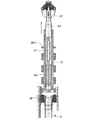
次に、コア部上層板1Aとコア部下層板1Bの間に残余されているカランドリア管4Dと圧力管5を取り外すために、第3の切断個所(ハ)に対して図11のように、メタルコアボーリング装置14でカランドリアタンク上管板4Bとの連結個所を切断するが、メタルコアボーリング装置14は先端ビット14aの先端側に拡縮径可能なエアバッグ装置24を装着すると共に、先端ビット14aの後端側にガイド管25を装着させており、ガイド管25を上部鉄水遮へい体スリーブ10を引き抜いた孔跡に嵌合させた状態で、先端ビット14aを回転させながらカランドリアタンク上管板4Bの内周面を切断し、カランドリア管4D及び圧力管5の上端側を切り離す(工程f)。
Next, in order to remove the
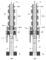
このように、工程fの切断作業でカランドリアタンク上管板4Bから、コア部上層板1Aとコア部下層板1B間の圧力管集合体等9(カランドリア管4Dと圧力管5)の上端側を切り離すと、既に工程dの切断作業で下端側がカランドリアタンク下管板4Cから切り離されていると共に、工程fの切断作業の終了時におけるメタルコアボーリング装置14のエアバッグ機構24は、図12(a)のように供給された空気又は水などの圧力流体によって膨張した状態で圧力管5の内周面に係止保持されているので、図12(b)のようにメタルコアボーリング装置14を上方へ引き上げると、カランドリア管4Dと圧力管5を引き抜いて取り外すことができる(工程g)。
In this way, the upper end side of the pressure tube assembly 9 (
次に、コア部下層板1Bの圧力管集合体等9との連結個所を縁切りするために、第5の切断個所(ホ)に対して図13のようにアブレイシブジェット切断装置15を圧力管下部延長管6B内に挿入すると共に、ジェットノズル15aを切断個所(ホ)と整合するように設定し、下部鉄水遮へい体管板3C−2に連結されている圧力管下部延長管6Bの途中及び、下部鉄水遮へい体スリーブ11の下端側を管内から切断し、下部鉄水遮へい体管板3C−2の下面でコア部下層板1Bの圧力管集合体等9を上下に分断する(工程h)。
Next, in order to cut off the connection portion of the core
このように、工程hの切断作業で下部鉄水遮へい体管板3C−2から、コア部下層板1Bより下側の圧力管集合体等9(圧力管下部延長管6Bの途中及び、下部鉄水遮へい体スリーブ11の下端側)を分断すると、既に工程dの切断作業で圧力管下部延長管6Bの上端側が圧力管5から切り離されていると共に、工程hの切断作業の終了時におけるアブレイシブジェット切断装置15のエアバッグ機構18,20は、図13のように供給された空気又は水などの圧力流体によって膨張した状態で圧力管下部延長管6Bの内周面に係止保持されているので、図14(a)のようにアブレイシブジェット切断装置15を下方へ引き下げると、コア部下層板1Bの下部鉄水遮へい体スリーブ11から圧力管下部延長管6Bを引き抜いて取り外すことができる(工程i)。
In this way, in the cutting operation of the process h, the lower iron water shielding
これにより、原子炉本体1のコア部上層板1A(上部鉄水遮へい体上管板3B−1、上部鉄水遮へい体遮へい板3B−2、上部鉄水遮へい体下管板3B−3、カランドリアタンク上管板4B)と、コア部下層板1B(カランドリアタンク下管板4C、3枚の下部鉄水遮へい体遮へい板3C−1、下部鉄水遮へい体管板3C−2)及び防振板8からは、コア部下層板1Bに残余する下部鉄水遮へい体スリーブ11以外の圧力管集合体等9は取り外されるので、同様に全ての圧力管集合体等9に対して工程a〜工程iを繰り返すことによって、図15のように全ての圧力管集合体等9を取り外すことができる。
As a result, the core
また、以上の実施形態による解体作業(タイプ1)では、工程h及び工程iによって圧力管下部延長管6Bを取り外すようにしているが、別の実施形態による解体作業(タイプ2)として、図4の工程図で示すように工程h及び工程iを省略して、下部鉄水遮へい体スリーブ11に加えて圧力管下部延長管6Bを残余させた状態で、圧力管集合体等9の一次解体(先行解体)作業を行う形態を採ることも可能である。
Further, in the dismantling operation (type 1) according to the above embodiment, the pressure pipe
なお、特に二次解体作業を水中で行う場合には、タイプ1ではコア部下層板1B側に残した下部鉄水遮へい体スリーブ11の下端部開口からの水の侵入を防止するために、例えば図14(b)のように下端部開口にシールプレート23を溶接するなどの水密処理を行うことが望ましく、タイプ2では圧力管下部延長管6Bの下端側に対し、工程aで取り外した特殊シールプラグ13を装着して水密処理を行うことが望ましい。
In particular, when the secondary dismantling work is performed in water, in order to prevent water from entering from the lower end opening of the lower iron water shielding
このような工程によって、原子炉本体1から圧力管集合体等9を先行解体する一次解体作業は終了するが、圧力管集合体等9を取り外すことで残ったカランドリアタンク3などを含む二次解体作業が容易であると共に、特に放射能レベルの高い圧力管集合体等9を一次解体作業で先行解体することによって、その後にレーザ切断装置その他公知の解体手段を用いて残りの原子炉本体1を解体する二次解体作業が安全に施工することができる。
By such a process, the primary dismantling work for dismantling the
また、これらの実施形態では圧力管集合体等9の下部鉄水遮へい体スリーブ11を圧力管下部延長管6Bに残余させ、特にタイプ2の場合には圧力管下部延長管6Bも残余させているが、これらの部材は核燃料や冷却用軽水が収容されていた上部側の圧力管集合体等9(圧力管上部延長管6A、上部鉄水遮へい体スリーブ10、圧力管5、カランドリア管4D)に比べて放射能レベルが低いので、残りの鉄水遮へい体3及びカランドリアタンク4と一緒に二次解体作業で解体することが可能である。
In these embodiments, the lower iron
また、各連結個所は原子炉本体の構造によって図示の実施形態とは異なる場合もあるので、その際には 原子炉本体の構造に適合した所望の連結個所を切断個所に設定し、図示の実施形態の場合と同様に、原子炉本体の上方に配置したコアボーリング装置の管外からの切断と、原子炉本体の下方に配置したアブレイシブジェット切断装置の管内からの切断によって、鉄水遮へい体3及びカランドリアタンク4から連結個所を切り離し、圧力管集合体等9の放射能レベルの高い部分を一次解体(先行解体)することが可能である。
In addition, each connection location may differ from the illustrated embodiment depending on the structure of the reactor body. In this case, a desired connection location suitable for the structure of the reactor body is set as the cutting location, and the illustrated implementation is performed. As in the case of the configuration, the iron bolus is shielded by cutting from the outside of the core boring device arranged above the reactor body and cutting from the inside of the abrasive jet cutting device arranged below the reactor body. It is possible to disconnect the connecting portion from the
1 原子炉本体
1A コア部上層板
3B−1 上部鉄水遮へい体上管板
3B−2 上部鉄水遮へい体遮へい板
3B−3 上部鉄水遮へい体下管板
4B カランドリアタンク上管板
1B コア部下層板
4C カランドリアタンク下管板
3C−1 下部鉄水遮へい体遮へい板
3C−2 下部鉄水遮へい体管板
2 生体遮へいコンクリート壁
3 鉄水遮へい体
3A 側部鉄水遮へい体
3B 上部鉄水遮へい体
3C 下部鉄水遮へい体
4 カランドリアタンク
4A 側壁板
4D カランドリア管
5 圧力管
6 圧力管延長管
6A 圧力管上部延長管
6B 圧力管下部延長管
7 制御棒案内管
8 防振板
9 圧力管集合体等
10 上部鉄水遮へい体スリーブ
11 下部鉄水遮へい体スリーブ
12 燃料棒収容プラグ
13 特殊シールプラグ
14 メタルコアボーリング装置
15 アブレイシブジェット切断装置
16 先端側管体
16a ジェットノズル
17,19 ベアリング機構
18,20,24 エアバッグ装置
21 基部側管体
22 チャック部
23 シールプレート
25 ガイド管
DESCRIPTION OF
Claims (3)
Priority Applications (1)
| Application Number | Priority Date | Filing Date | Title |
|---|---|---|---|
| JP2004102446A JP4167198B2 (en) | 2004-03-31 | 2004-03-31 | Reactor body disassembly method |
Applications Claiming Priority (1)
| Application Number | Priority Date | Filing Date | Title |
|---|---|---|---|
| JP2004102446A JP4167198B2 (en) | 2004-03-31 | 2004-03-31 | Reactor body disassembly method |
Publications (2)
| Publication Number | Publication Date |
|---|---|
| JP2005291710A true JP2005291710A (en) | 2005-10-20 |
| JP4167198B2 JP4167198B2 (en) | 2008-10-15 |
Family
ID=35324824
Family Applications (1)
| Application Number | Title | Priority Date | Filing Date |
|---|---|---|---|
| JP2004102446A Expired - Fee Related JP4167198B2 (en) | 2004-03-31 | 2004-03-31 | Reactor body disassembly method |
Country Status (1)
| Country | Link |
|---|---|
| JP (1) | JP4167198B2 (en) |
Cited By (7)
| Publication number | Priority date | Publication date | Assignee | Title |
|---|---|---|---|---|
| KR101859359B1 (en) | 2011-01-14 | 2018-05-21 | 지이-히타치 뉴클리어 에너지 캐나다 인코퍼레이티드 | Method for removal of pressure tubes and calandria tubes from a nuclear reactor |
| KR102025875B1 (en) * | 2018-07-13 | 2019-09-26 | 한국수력원자력 주식회사 | Method for decommissioning pressure heavy water reactor facilities |
| KR102025874B1 (en) * | 2018-07-13 | 2019-09-26 | 한국수력원자력 주식회사 | Apparatus for decommissioning pressure heavy water reactor facilities and method for decommissioning pressure heavy water reactor facilities |
| WO2020149567A1 (en) * | 2019-01-18 | 2020-07-23 | 한국수력원자력 주식회사 | Apparatus and method for decommissioning heavy-water reactor facility |
| WO2020149568A1 (en) * | 2019-01-18 | 2020-07-23 | 한국수력원자력 주식회사 | Apparatus and method for dismantling heavy-water reactor facility |
| WO2020166915A1 (en) * | 2019-02-14 | 2020-08-20 | 한국수력원자력 주식회사 | Method for disassembling heavy-water reactor equipment by using cutting device |
| WO2020180018A1 (en) * | 2019-03-04 | 2020-09-10 | 한국수력원자력 주식회사 | Exposure protection device for decommission of heavy water reactor facility, and method for decommissioning heavy water reactor facility by using same |
Families Citing this family (1)
| Publication number | Priority date | Publication date | Assignee | Title |
|---|---|---|---|---|
| MXPA02001620A (en) | 1999-08-14 | 2002-07-02 | Procter & Gamble | Methods and systems for utilizing delayed dilution, mixing and filtering to provide customized varieties of fresh-brewed coffee on-demand. |
Citations (5)
| Publication number | Priority date | Publication date | Assignee | Title |
|---|---|---|---|---|
| JPS55122197A (en) * | 1979-03-14 | 1980-09-19 | Hitachi Ltd | Device for handling radioactive material |
| JPH0192697A (en) * | 1987-10-05 | 1989-04-11 | Kajima Corp | Method for cutting and disassembling cylindrical structure |
| JP2000056079A (en) * | 1998-08-03 | 2000-02-25 | Able:Kk | Replacing method for buried funnel of power plant and pipe cutter |
| JP2001096366A (en) * | 1999-09-27 | 2001-04-10 | Hitachi Ltd | Remote working device |
| JP2004212149A (en) * | 2002-12-27 | 2004-07-29 | Sumitomo Mitsui Construction Co Ltd | Reactor dismantling and removal methods |
-
2004
- 2004-03-31 JP JP2004102446A patent/JP4167198B2/en not_active Expired - Fee Related
Patent Citations (5)
| Publication number | Priority date | Publication date | Assignee | Title |
|---|---|---|---|---|
| JPS55122197A (en) * | 1979-03-14 | 1980-09-19 | Hitachi Ltd | Device for handling radioactive material |
| JPH0192697A (en) * | 1987-10-05 | 1989-04-11 | Kajima Corp | Method for cutting and disassembling cylindrical structure |
| JP2000056079A (en) * | 1998-08-03 | 2000-02-25 | Able:Kk | Replacing method for buried funnel of power plant and pipe cutter |
| JP2001096366A (en) * | 1999-09-27 | 2001-04-10 | Hitachi Ltd | Remote working device |
| JP2004212149A (en) * | 2002-12-27 | 2004-07-29 | Sumitomo Mitsui Construction Co Ltd | Reactor dismantling and removal methods |
Cited By (18)
| Publication number | Priority date | Publication date | Assignee | Title |
|---|---|---|---|---|
| KR101859359B1 (en) | 2011-01-14 | 2018-05-21 | 지이-히타치 뉴클리어 에너지 캐나다 인코퍼레이티드 | Method for removal of pressure tubes and calandria tubes from a nuclear reactor |
| KR102025875B1 (en) * | 2018-07-13 | 2019-09-26 | 한국수력원자력 주식회사 | Method for decommissioning pressure heavy water reactor facilities |
| KR102025874B1 (en) * | 2018-07-13 | 2019-09-26 | 한국수력원자력 주식회사 | Apparatus for decommissioning pressure heavy water reactor facilities and method for decommissioning pressure heavy water reactor facilities |
| WO2020013516A1 (en) * | 2018-07-13 | 2020-01-16 | 한국수력원자력 주식회사 | Apparatus for decommissioning heavy-water reactor facilities and method for decommissioning heavy-water reactor facilities |
| WO2020013518A1 (en) * | 2018-07-13 | 2020-01-16 | 한국수력원자력 주식회사 | Method for decommissioning heavy water reactor facility |
| US11417436B2 (en) | 2018-07-13 | 2022-08-16 | Korea Hydro & Nuclear Power Co., Ltd. | Apparatus for decommissioning heavy-water reactor facilities and method for decommissioning heavy-water reactor facilities |
| US11984233B2 (en) | 2018-07-13 | 2024-05-14 | Korea Hydro & Nuclear Power Co., Ltd. | Method for decommissioning heavy water reactor facility |
| WO2020149568A1 (en) * | 2019-01-18 | 2020-07-23 | 한국수력원자력 주식회사 | Apparatus and method for dismantling heavy-water reactor facility |
| KR20200089887A (en) * | 2019-01-18 | 2020-07-28 | 한국수력원자력 주식회사 | Aparatus and method for dismantling for heavy water reactor facilities |
| US12176115B2 (en) | 2019-01-18 | 2024-12-24 | Korea Hydro & Nuclear Power Co., Ltd. | Aparatus and method for dismantling for heavy water reactor facilities |
| KR102185335B1 (en) * | 2019-01-18 | 2020-12-01 | 한국수력원자력 주식회사 | Aparatus and method for dismantling for heavy water reactor facilities |
| US20220068514A1 (en) * | 2019-01-18 | 2022-03-03 | Korea Hydro & Nuclear Power Co., Ltd. | Aparatus and method for dismantling for heavy water reactor facilities |
| US11717902B2 (en) | 2019-01-18 | 2023-08-08 | Korea Hydro & Nuclear Power Co., Ltd. | Apparatus for dismantling for heavy water reactor facilities |
| WO2020149567A1 (en) * | 2019-01-18 | 2020-07-23 | 한국수력원자력 주식회사 | Apparatus and method for decommissioning heavy-water reactor facility |
| WO2020166915A1 (en) * | 2019-02-14 | 2020-08-20 | 한국수력원자력 주식회사 | Method for disassembling heavy-water reactor equipment by using cutting device |
| US11830633B2 (en) | 2019-02-14 | 2023-11-28 | Korea Hydro & Nuclear Power Co., Ltd. | Method for disassembling heavy-water reactor equipment by using cutting device |
| US20220148748A1 (en) * | 2019-02-14 | 2022-05-12 | Korea Hydro & Nuclear Power Co., Ltd. | Method for disassembling heavy-water reactor equipment by using cutting device |
| WO2020180018A1 (en) * | 2019-03-04 | 2020-09-10 | 한국수력원자력 주식회사 | Exposure protection device for decommission of heavy water reactor facility, and method for decommissioning heavy water reactor facility by using same |
Also Published As
| Publication number | Publication date |
|---|---|
| JP4167198B2 (en) | 2008-10-15 |
Similar Documents
| Publication | Publication Date | Title |
|---|---|---|
| KR101859359B1 (en) | Method for removal of pressure tubes and calandria tubes from a nuclear reactor | |
| JP4124643B2 (en) | Reactor dismantling and removal methods | |
| WO2011040096A1 (en) | Nozzle welding method, nozzle part repairing method, and nozzle welded structure | |
| JP4167198B2 (en) | Reactor body disassembly method | |
| TWI445895B (en) | Method and apparatus for repairing a core spray downcomer pipe in a nuclear reactor | |
| US4173060A (en) | System and method for retubing a steam generator | |
| JP2007232457A (en) | Repairing method of penetration nozzle, and plug for nozzle port | |
| JP6014363B2 (en) | Discharge device | |
| US5070589A (en) | Process for servicing a jet pump hold down beam in a nuclear reactor | |
| DE2837948A1 (en) | METHOD FOR REMOVING THE HEAT EXCHANGER TUBES FROM A STEAM GENERATOR | |
| US4995158A (en) | Apparatus for servicing a jet pump hold down beam in a nuclear reactor | |
| Ren et al. | Design and application of a special underwater cutting device for the decommissioning of the first HWRR reactor in China | |
| JP5674624B2 (en) | Internal observation method of the containment vessel | |
| KR101942997B1 (en) | Method for removal of radioactivation structure in nuclear power plant | |
| JPH06103355B2 (en) | Method of repairing neutron flux monitor housing | |
| JP4648266B2 (en) | Neutron measuring tube connection method and replacement method, and neutron measuring tube | |
| JP2533622B2 (en) | Method of repairing neutron flux monitor housing | |
| EP4180170A1 (en) | Method for dismantling steam generator | |
| Bouilly et al. | SUPERPHENIX Dismantling-Status and lessons learned | |
| JP6446370B2 (en) | System and method for disposing of one or more radioactive parts from a nuclear power plant reactor | |
| JP4488591B2 (en) | Maintenance method of core spare purger | |
| JP4751849B2 (en) | Opening device for sealed container containing radioactive gas | |
| JP4580908B2 (en) | How to remove the jet pump retainer | |
| JP2014020883A (en) | Device for cleaning and decontaminating reactor pressure vessel nozzle part | |
| JP6170414B2 (en) | PCV survey system and PCV survey method |
Legal Events
| Date | Code | Title | Description |
|---|---|---|---|
| A621 | Written request for application examination |
Free format text: JAPANESE INTERMEDIATE CODE: A621 Effective date: 20060731 |
|
| A977 | Report on retrieval |
Free format text: JAPANESE INTERMEDIATE CODE: A971007 Effective date: 20070925 |
|
| A131 | Notification of reasons for refusal |
Free format text: JAPANESE INTERMEDIATE CODE: A131 Effective date: 20080422 |
|
| A521 | Request for written amendment filed |
Free format text: JAPANESE INTERMEDIATE CODE: A523 Effective date: 20080617 |
|
| TRDD | Decision of grant or rejection written | ||
| A01 | Written decision to grant a patent or to grant a registration (utility model) |
Free format text: JAPANESE INTERMEDIATE CODE: A01 Effective date: 20080729 |
|
| A01 | Written decision to grant a patent or to grant a registration (utility model) |
Free format text: JAPANESE INTERMEDIATE CODE: A01 |
|
| A61 | First payment of annual fees (during grant procedure) |
Free format text: JAPANESE INTERMEDIATE CODE: A61 Effective date: 20080731 |
|
| R150 | Certificate of patent or registration of utility model |
Ref document number: 4167198 Country of ref document: JP Free format text: JAPANESE INTERMEDIATE CODE: R150 Free format text: JAPANESE INTERMEDIATE CODE: R150 |
|
| FPAY | Renewal fee payment (event date is renewal date of database) |
Free format text: PAYMENT UNTIL: 20110808 Year of fee payment: 3 |
|
| FPAY | Renewal fee payment (event date is renewal date of database) |
Free format text: PAYMENT UNTIL: 20110808 Year of fee payment: 3 |
|
| FPAY | Renewal fee payment (event date is renewal date of database) |
Free format text: PAYMENT UNTIL: 20140808 Year of fee payment: 6 |
|
| R250 | Receipt of annual fees |
Free format text: JAPANESE INTERMEDIATE CODE: R250 |
|
| R250 | Receipt of annual fees |
Free format text: JAPANESE INTERMEDIATE CODE: R250 |
|
| R250 | Receipt of annual fees |
Free format text: JAPANESE INTERMEDIATE CODE: R250 |
|
| R250 | Receipt of annual fees |
Free format text: JAPANESE INTERMEDIATE CODE: R250 |
|
| R250 | Receipt of annual fees |
Free format text: JAPANESE INTERMEDIATE CODE: R250 |
|
| R250 | Receipt of annual fees |
Free format text: JAPANESE INTERMEDIATE CODE: R250 |
|
| R250 | Receipt of annual fees |
Free format text: JAPANESE INTERMEDIATE CODE: R250 |
|
| R250 | Receipt of annual fees |
Free format text: JAPANESE INTERMEDIATE CODE: R250 |
|
| LAPS | Cancellation because of no payment of annual fees |