JP2005291726A - Biochemical analyzer - Google Patents
Biochemical analyzer Download PDFInfo
- Publication number
- JP2005291726A JP2005291726A JP2004102747A JP2004102747A JP2005291726A JP 2005291726 A JP2005291726 A JP 2005291726A JP 2004102747 A JP2004102747 A JP 2004102747A JP 2004102747 A JP2004102747 A JP 2004102747A JP 2005291726 A JP2005291726 A JP 2005291726A
- Authority
- JP
- Japan
- Prior art keywords
- measurement
- light
- measurement light
- container
- sample
- Prior art date
- Legal status (The legal status is an assumption and is not a legal conclusion. Google has not performed a legal analysis and makes no representation as to the accuracy of the status listed.)
- Withdrawn
Links
- 238000005259 measurement Methods 0.000 claims abstract description 162
- 239000003153 chemical reaction reagent Substances 0.000 claims abstract description 40
- 238000012742 biochemical analysis Methods 0.000 claims abstract description 12
- 239000007788 liquid Substances 0.000 claims abstract description 10
- 230000001678 irradiating effect Effects 0.000 claims abstract description 7
- 230000004907 flux Effects 0.000 claims abstract description 5
- 230000003287 optical effect Effects 0.000 claims description 96
- 239000000203 mixture Substances 0.000 claims description 5
- 239000000284 extract Substances 0.000 claims description 2
- 239000000523 sample Substances 0.000 description 26
- 238000010586 diagram Methods 0.000 description 17
- 238000000034 method Methods 0.000 description 8
- 238000004140 cleaning Methods 0.000 description 7
- 230000005540 biological transmission Effects 0.000 description 6
- 238000005070 sampling Methods 0.000 description 4
- 239000008280 blood Substances 0.000 description 3
- 210000004369 blood Anatomy 0.000 description 3
- 230000001105 regulatory effect Effects 0.000 description 3
- 238000003756 stirring Methods 0.000 description 3
- 239000011259 mixed solution Substances 0.000 description 2
- 230000002093 peripheral effect Effects 0.000 description 2
- 239000012466 permeate Substances 0.000 description 2
- 238000005406 washing Methods 0.000 description 2
- 238000013019 agitation Methods 0.000 description 1
- 230000015572 biosynthetic process Effects 0.000 description 1
- 238000001816 cooling Methods 0.000 description 1
- 230000002550 fecal effect Effects 0.000 description 1
- 238000003384 imaging method Methods 0.000 description 1
- 238000000691 measurement method Methods 0.000 description 1
- 238000002156 mixing Methods 0.000 description 1
- 239000000843 powder Substances 0.000 description 1
- 239000012488 sample solution Substances 0.000 description 1
- 239000000126 substance Substances 0.000 description 1
- 210000002700 urine Anatomy 0.000 description 1
Images







Landscapes
- Investigating Or Analysing Materials By The Use Of Chemical Reactions (AREA)
- Automatic Analysis And Handling Materials Therefor (AREA)
- Investigating Or Analysing Materials By Optical Means (AREA)
Abstract
Description
本発明は、検体と試薬との混合液を収容して所定の測定点にある測定容器に測定光を照射しその測定容器を透過した測定光を検出することにより検体の生化学分析を行なう生化学分析装置に関する。 In the present invention, a biochemical analysis of a specimen is performed by containing a liquid mixture of a specimen and a reagent, irradiating the measurement container at a predetermined measurement point with the measurement light, and detecting the measurement light transmitted through the measurement container. The present invention relates to a chemical analyzer.
人体の血液等を検体とし、キュベットと呼ばれる透明の測定容器内にこの検体と試薬を注入して反応させ、その検体と試薬とからなる試料液の反応による呈色を光学的に測定することにより検体の生化学分析を行なう生化学分析装置が知られている(例えば特許文献1参照)。 By using human blood or the like as a sample, injecting and reacting this sample and reagent in a transparent measurement container called a cuvette, and optically measuring the coloration caused by the reaction of the sample liquid consisting of the sample and the reagent A biochemical analyzer that performs biochemical analysis of a specimen is known (see, for example, Patent Document 1).
キュベット内の試料液を光学的に測定する方法の1つとして、そのキュベットに測定光を照射しそのキュベットを透過してきた測定光を分光して特定波長の光を測定する方法が知られている(特許文献2参照)。 As one of the methods for optically measuring the sample liquid in the cuvette, a method is known in which the cuvette is irradiated with measurement light and the measurement light transmitted through the cuvette is dispersed to measure light of a specific wavelength. (See Patent Document 2).
ただし、この方法は大がかりな分光器を必要とし大がかりな測定装置となるおそれがある。 However, this method requires a large-scale spectroscope and may be a large-scale measuring device.
これに対し、キュベットを透過してきた測定光から光学フィルタで所望の波長の光を抽出して測定する方法も提案されている(特許文献3参照)。この測定方法は、比較的小規模の生化学分析装置に向いている。
上記の、キュベットに測定光を照射しそのキュベットを透過してきた測定光から所望の波長の光を抽出して測定する方法には、様々な問題が内在している。 Various problems are inherent in the above-described method of measuring light by irradiating the cuvette with measurement light and extracting light of a desired wavelength from the measurement light transmitted through the cuvette.
図14は、キュベットに測定光を照射する照射部の従来例を示す図である。 FIG. 14 is a diagram illustrating a conventional example of an irradiation unit that irradiates a cuvette with measurement light.
この図14に示す照射部は、基本的には、上述の特許文献3の図1に示すものと同様のものである。 The irradiation unit shown in FIG. 14 is basically the same as that shown in FIG.
フィラメントを有するランプ11が前方に開口したランプハウス12に収容されており、そのランプハウス12の開口近傍には、第1レンズ13が配置されている。この第1レンズ13はランプ11をキュベット20に結像することにより、ランプ11の光をそのキュベット20に集光している。
A
第1レンズ13を出射した測定光はアパーチャ14の開口を通過してキュベット20に照射され、そのキュベット20を透過した測定光はもう1つのアパーチャ15の開口を通過して、ここには図示しない受光部へと進む。
The measurement light emitted from the
図15は、図14に一点鎖線で示すA−A′面の光像を示す図である。 FIG. 15 is a diagram showing an optical image of the AA ′ plane indicated by a one-dot chain line in FIG.
この図15に示すように、ここには、測定光として本来有効な中央部分20aの回りにフレアが生じた周囲部分20bが存在する。このフレアは、ランプハウス12の内壁面での反射光(図14に二点鎖線で示す)がキュベット20に到達することにより生じており、このフレアの存在が、キュベット20の透過光量を測定したときの測定誤差の原因となるという問題がある。
As shown in FIG. 15, there is a
図16は、キュベットを透過した後の測定光を取り扱う受光部の従来例を示す図である。図16(A)はその光学系を示し、図16(B)は光学フィルタと測定光束との位置関係を示している。 FIG. 16 is a diagram illustrating a conventional example of a light receiving unit that handles measurement light after passing through a cuvette. FIG. 16A shows the optical system, and FIG. 16B shows the positional relationship between the optical filter and the measurement light beam.
キュベット20(図14参照)を透過してきた測定光はレンズ31を通りさらに光学フィルタ32を透過して図示しない光検出器に入射する。ここで、光学フィルタ32は、後で説明するように(図18参照)、複数配列されていて切替式となっている場合が多い。この光学フィルタ32が切替式となっていると、切替え時に位置ずれが生ずるおそれがある。
The measurement light that has passed through the cuvette 20 (see FIG. 14) passes through the
図17は、光学フィルタの位置ずれに起因する問題点の説明図である。図17(A)は光学フィルタの位置がずれたときの光学系を示し、図17(B)はそのときの光学フィルタと測定光束との位置関係を示している。 FIG. 17 is an explanatory diagram of a problem caused by the positional deviation of the optical filter. FIG. 17A shows the optical system when the position of the optical filter is displaced, and FIG. 17B shows the positional relationship between the optical filter and the measurement light beam at that time.
フィルタ切替機構を持つ光学系で光学フィルタ32の有効範囲いっぱいに測定光束を通すと、光学フィルタ32の位置がずれた場合に、測定光束の一部が光学フィルタの枠部分に当たってその光学フィルタを正常に透過せず、これが光量変動の原因となり、測定誤差の増大を招く。
If a measurement beam is passed through the effective range of the
図18は、ターレット式のフィルタ板を示す図、図19、図20は受光部の光学系を示す側面図および斜視図である。 18 is a view showing a turret type filter plate, and FIGS. 19 and 20 are a side view and a perspective view showing an optical system of a light receiving section.
光学フィルタを切替式とするために通常用いられる構成として、図18に示すような、複数の光学フィルタ32A,32B,…,32Nを円状に配置したフィルタ板33を用意し、図19,図20に示すように、そのフィルタ板33を光検出器34の前面に配置して光学フィルタ33A,33B,…,33Nの配置ピッチ単位で回転させ、測定光の光路上に所望の光学フィルタを配置することにより、測定光の中から所望の波長の光を抽出して光検出器34に入射させる。
As a configuration usually used for switching the optical filter, a
ここで、測定光の中から異なる2つの波長の光をそれぞれ抽出して測定する必要がある場合がある。
しかしながら、このようなフィルタ切替機構を採用すると光学フィルタの切替に時間がかかるため、測定に要する時間が長くかかるという問題がある。
Here, it may be necessary to extract and measure two different wavelengths of light from the measurement light.
However, when such a filter switching mechanism is employed, it takes time to switch the optical filter, and there is a problem that it takes a long time for measurement.
一方、キュベットをターンテーブル上に配置して順次回転する構成の場合、キュベットは長時間は同じ測定点にとどまっておらず、測定のチャンスを1回逃がすとそのキュベットの測定についてはもう一巡するまで待つ必要がある。 On the other hand, when the cuvette is arranged on the turntable and rotates sequentially, the cuvette does not stay at the same measurement point for a long time, and once the measurement chance is missed, the measurement of that cuvette is completed once more. I need to wait.
本発明は、上記事情に鑑み、キュベット内の試料液の測定方法が改善された生化学分析装置を提供することを目的とする。 In view of the above circumstances, an object of the present invention is to provide a biochemical analyzer with an improved method for measuring a sample solution in a cuvette.
上記目的を達成する本発明の生化学分析装置のうちの第1の生化学分析装置は、検体と試薬との混合液を収容して所定の測定点にある測定容器に測定光を照射しその測定容器を透過した測定光を検出することにより検体の生化学分析を行なう生化学分析装置において、ランプと、そのランプを収容する、前方に開口したランプハウスと、ランプハウスの開口近傍に配置され、ランプからの光をその測定点に導く第1レンズと、第1レンズから出射した光の光束を規制する開口部と、その開口部を測定点近傍に結像する第2レンズと、測定容器を透過した測定光を受光する受光部とを備えたことを特徴とする。 The first biochemical analyzer of the present invention that achieves the above object is a first biochemical analyzer that contains a mixture of a specimen and a reagent, irradiates a measurement container at a predetermined measurement point with measurement light, and In a biochemical analyzer that performs biochemical analysis of a specimen by detecting measurement light that has passed through a measurement container, a lamp, a lamp house that opens in front of the lamp, and a lamp house that is disposed in the vicinity of the lamp house A first lens that guides light from the lamp to the measurement point, an opening that restricts the luminous flux of the light emitted from the first lens, a second lens that forms an image of the opening near the measurement point, and a measurement container And a light receiving portion for receiving the measurement light that has passed therethrough.
本発明の第1の生化学分析装置は、第1のレンズがランプからの光を測定点に導くものであり、さらに、第1レンズから出射した光の光束を規制する開口部と、その開口部をその測定点に結像する第2レンズを備えたものであるため、周囲にフレアの領域は発生せず、高精度の測定が行なわれる。 In the first biochemical analyzer of the present invention, the first lens guides the light from the lamp to the measurement point, and further, an opening for restricting the luminous flux of the light emitted from the first lens, and the opening Since the second lens that forms an image at the measurement point is provided, a flare region does not occur in the periphery, and high-precision measurement is performed.
また、本発明の生化学分析装置のうちの第2の生化学分析装置は、検体と試薬との混合液を収容して所定の測定点にある測定容器に測定光を照射しその測定容器を透過した測定光を検出することにより検体の生化学分析を行なう生化学分析装置において、上記測定容器に測定光を照射する照射部と、上記測定点を通過した測定光の光路に切替自在に進出して、測定光の中から所望の波長の光を抽出する光学素子と、その光学素子の前もしくは後に配置され、測定光の通過領域を規制する開口部と、その光学素子および開口部の双方を経由した後の測定光を検出する検出器とを備えたことを特徴とする。 Further, the second biochemical analyzer of the biochemical analyzer of the present invention contains a mixed solution of a specimen and a reagent, irradiates the measurement container at a predetermined measurement point with measurement light, and uses the measurement container. In a biochemical analyzer that performs biochemical analysis of a specimen by detecting transmitted measurement light, the irradiation section for irradiating the measurement light to the measurement container and the optical path of the measurement light that has passed through the measurement point can be switched. An optical element that extracts light of a desired wavelength from the measurement light, an opening that is disposed before or after the optical element and restricts the passage region of the measurement light, and both the optical element and the opening And a detector for detecting the measurement light after passing through.
本発明の第2の生化学分析装置は、上記光学素子、例えば上述したターレット式の光学フィルタの前あるいは後に開口部を配置して測定光の通過領域を規制したため、光学フィルタ等の光学素子に位置ずれがあってもその光学素子の通過光量は安定しており、高精度の測定が可能となる。 In the second biochemical analyzer of the present invention, an opening is disposed before or after the optical element, for example, the turret optical filter described above, to restrict the measurement light passage region. Even if there is a positional shift, the amount of light passing through the optical element is stable, and high-precision measurement is possible.
さらに、本発明の生化学分析装置のうちの第3の生化学分析装置は、検体と試薬との混合液を収容して所定の測定点にある測定容器に測定光を照射しその測定容器を透過した測定光を検出することにより検体の生化学分析を行なう生化学分析装置において、上記測定容器に測定光を照射する照射部と、複数の光学フィルタが配列されて一体的に移動することによりそれら複数の光学フィルタの切替えを行なうフィルタ板と、上記測定点を通過した測定光を複数光束の測定光に分割して、それら複数光束の測定光をそれぞれ異なる光学フィルタに導く光束分割光学系と、上記フィルタ板を経由した後の複数光束の測定光それぞれを検出する複数の検出器とを備えたことを特徴とする。 Furthermore, a third biochemical analyzer of the biochemical analyzers of the present invention contains a mixed solution of a specimen and a reagent, irradiates the measurement container at a predetermined measurement point with measurement light, and uses the measurement container. In a biochemical analyzer that performs biochemical analysis of a specimen by detecting transmitted measurement light, an irradiation unit that irradiates the measurement light to the measurement container and a plurality of optical filters are arranged and moved integrally. A filter plate for switching the plurality of optical filters, and a beam splitting optical system that divides the measurement light that has passed through the measurement point into measurement beams of a plurality of beams, and guides the measurement beams of the plurality of beams to different optical filters, respectively. And a plurality of detectors for detecting the measurement light beams of the plurality of light beams after passing through the filter plate.
本発明の第3の生化学分析装置は、測定光束を複数に分割して複数の測定光束について並列に測定するものであるため、高速測定が可能となる。 Since the third biochemical analyzer of the present invention divides the measurement light beam into a plurality of parts and measures the plurality of measurement light beams in parallel, high-speed measurement is possible.
以上説明したように本発明によれば、測定容器内の試料液の測定方法の改善が図られる。 As described above, according to the present invention, the method for measuring the sample liquid in the measurement container can be improved.
以下、本発明の実施形態について説明する。 Hereinafter, embodiments of the present invention will be described.
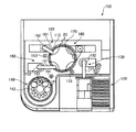
図1は、生化学分析装置の一実施形態を示す概要図である。 FIG. 1 is a schematic diagram showing an embodiment of a biochemical analyzer.
この生化学分析装置100には、ターンテーブル110が備えられており、そのターンテーブル110には、多数の測定容器としてのキュベット20が円状に配置されている。
This
そのターンテーブル110の周囲には、検体供給部120、検体サンプリング部130、試薬保管部140、試薬サンプリング部150、撹拌部160、反応部170、および洗浄部180が配備されている。
Around the
検体供給部120には、多数の検体(例えば人体の血液、尿、便等)が各容器に入って配列されており、検体サンプリング部130には、その容器から検体を吸引してターンテーブル110上の多数のキュベット20のうちのあらかじめプログラムされたキュベットに注入する検体ピペット131が備えられている。この検体ピペット131は、回転軸132を中心にして、検体供給部120と、洗浄部133と、ターンテーブル110上のキュベット20との間で往復回動し、検体供給部120に配列された検体容器から検体を吸引してその検体をターンテーブル110上のキュベット20に注入し、洗浄部133で次の検体の吸引のために洗浄される。
A large number of samples (for example, human blood, urine, stool, etc.) are arranged in each container in the
また、試薬保冷庫140は、試薬が入った試薬容器141を収容して所定の冷却温度に保冷するものであり、また、その試薬保冷庫140の上蓋142には吸入口143が設けられている。その試薬保冷庫140内の試薬容器141はターンテーブル上に置かれていて回転自在となっており、所望の試薬の入った試薬容器が吸入口143の下に配置されるようにそのターンテーブルが回転する。試薬サンプリング部150には、試薬ピペット151が備えられており、その試薬ピペット151は、回転軸152を中心にして、試薬保冷庫140の吸引口143と、洗浄部153と、ターンテーブル110上のキュベット20との間で往復回動し、試薬ピペット151の先端のプローブ(図示せず)を試薬保冷庫140の上蓋142の吸入口143に挿入してその下にある試薬容器141内の試薬を吸引し、その試薬をターンテーブル110上のキュベット20に注入し、洗浄部153で次の試薬の吸引のために洗浄される。
The
撹拌部160には、先端に棒状の撹拌子(図示せず)を備えた攪拌器161が備えられている。この撹拌器161は、回転軸162を中心にして、ターンテーブル110上のキュベット20と洗浄部163との間で往復回動し、キュベット20内に撹拌子を挿入してそのキュベット20内に注入されている検体と試薬を撹拌、混合し、洗浄部163ではその先端の撹拌子が次のキュベットが撹拌、混合のために洗浄される。
The stirring
反応部170には、キュベット20内の撹拌、混合された検体と試薬とからなる試料液の呈色反応の濃度検出のための測定を行なう測定器(図示せず)が配置されており、これにより検体の生化学分析が行なわれる。
The
さらに洗浄部180では、ターンテーブル110上の反応部170における測定の終了したキュベット20が洗浄され、次の検体の生化学分析のために再利用される。
Further, in the
図2は、図1の生化学分析装置の動作シーケンス例を示す図である。 FIG. 2 is a diagram showing an example of an operation sequence of the biochemical analyzer of FIG.
図2(A)は、一般的な生化学分析を行なうときの動作シーケンスであり、先ず、ターンテーブル110上のあるキュベット20に試薬1が分注され、そのまま5分間、所定の温度に安定するよう温度調節が行なわれる。次いでその同じキュベット20に検体が分注され、さらに試薬2が分注され、撹拌されて測定が行なわれ、最後にそのキュベット20が洗浄される。この間約10分ほどの時間がかかる。このような動作シーケンスが、ターンテーブル110に載っている多数のキュベット20について並列的に実行される。
FIG. 2A shows an operation sequence when performing general biochemical analysis. First, the reagent 1 is dispensed into a
図2(B)は、便潜血測定時の動作シーケンスである。この場合、順に試薬1分注、検体分注、試薬2分注が行なわれ、撹拌、測定、洗浄が行なわれて、1検体あたり約6分で終了する。この場合も、ターンテーブル110に載せられている多数のキュベット20について、この動作シーケンスが並行的に実行される。
FIG. 2B shows an operation sequence during fecal occult blood measurement. In this case, reagent 1 dispensing, sample dispensing, and reagent 2 dispensing are sequentially performed, stirring, measurement, and washing are performed, and the process is completed in about 6 minutes per sample. Also in this case, this operation sequence is executed in parallel for a large number of
図1の生化学分析装置100には、図2(A),(B)に例示するような動作シーケンスが複数用意されており、その目的に応じて適切な動作シーケンスに切り替えられる。図1の生化学分析装置100では、動作シーケンスの切り替えは、オペレータによる手動操作で行われるが、その他にも、検体の種類に応じた検体容器を用い、その検体容器の種類を検出して動作シーケスを切り替えるようにしてもよい。
The
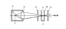
図3は、図1に示す生化学分析装置100の反応部170に配置された測定器のうちの、ターンテーブル110上のキュベット20に測定光を照射する照射部を示す図である。
FIG. 3 is a diagram showing an irradiating unit that irradiates the
図14に示す従来の照射部の構成要素に対応する構成要素には、図14に付した符号と同一の符号を付して示し、相違点を中心に説明する。 Components corresponding to the components of the conventional irradiation unit shown in FIG. 14 are denoted by the same reference numerals as those shown in FIG. 14, and differences will be mainly described.
前方に開口を有するランプハウス12内にフィラメントを有するランプ11が収容されている。そのランプハウス12の開口近傍には、第1レンズ13が配置されている。図14の従来例における第1レンズ13は、ランプ11をキュベット20に結像するレンズであるが、この図3に示す第1レンズ13は、ランプ11を結像することなく、ランプ11から発せられた光をほぼ平行光にすることにより、キュベット20が通過する測定点へのランプ11のフィラメントの結像を避けつつ、そのランプ11からの光をその測定点に導くレンズである。
A
また、ランプハウス12の前面には、第1レンズ13が出射した光束を規制する開口部としてのアパーチャ16が配置されており、このアパーチャ16部ではフィラメントの結像がなく、また、ランプハウス12内の不要な反射光も結像されていない。さらに、そのアパーチャ16よりも前方に、そのアパーチャ16を測定点に結像する第2レンズ17が配置されている。ここでアパーチャ16が結像される測定点は、キュベット20の中心A−A′であることが好ましいが、キュベット20内で結像していればよい。
In addition, an aperture 16 as an opening for restricting the light beam emitted from the
第2レンズ17を出射した測定光は、もう1つのアパーチャ14の開口を通過して、測定点を通過中のキュベット20に照射され、そのキュベット20を透過した測定光は、さらにもう1つのアパーチャ15の開口を通過して、ここには図示しない受光部へと進みその光量が測定される。
The measurement light emitted from the
図4は、図3に一点鎖線で示すA−A′面の光像を示す図である。 FIG. 4 is a diagram showing an optical image of the AA ′ plane indicated by a one-dot chain line in FIG.
ここには、アパーチャ16の像としての、測定光として本来有効な中央部分20aのみがくっきりと結像されており、図15に示すようなフレアが生じた周囲部分20bは存在しない。
Here, only the
このように、図3の照射部は、ランプ11のフィラメントがキュベット20の位置に結像されるのが避けられる。また、同時に発光部近傍の不要な反射光を取り除くことができる光学系を有し、したがってフレアが防止され、高精度の測定が行なわれる。
As described above, the irradiation unit in FIG. 3 can avoid the filament of the
図5は、図1に示す生化学分析装置100の反応部170に配置された測定器のうちの、ターンテーブル110上のキュベット20を透過した測定光を受光する受光部の一例を示す図である。図5(A)は、その光学系を示し、図5(B)は光学フィルタと測定光束との位置関係を示している。
FIG. 5 is a diagram illustrating an example of a light receiving unit that receives measurement light transmitted through the
図16,図17に示す従来の受光部の構成要素に対応する構成要素には、図16,図17に付した符号と同一の符号を付して示し相違点を中心に説明する。 Components corresponding to those of the conventional light receiving unit shown in FIGS. 16 and 17 are denoted by the same reference numerals as those shown in FIGS. 16 and 17, and the differences will be mainly described.
測定点を通過中のキュベット20(図3参照)を透過してきた測定光は、レンズ31を通り、さらに、固定アパーチャ35の開口および光学フィルタ32を透過して図示しない光検出器に入射する。ここで、この図5に示す受光部の、図16に示す従来の受光部との相違点は、光学フィルタ32の前面に固定アパーチャ35が配置される点である。
The measurement light that has passed through the cuvette 20 (see FIG. 3) passing through the measurement point passes through the
光学フィルタ32は、図18を参照して説明したように、複数配列されたターレット式となっている。この光学フィルタ32を切り替えると光の切替時に位置ずれを生じることがある。
As described with reference to FIG. 18, the
図6は、図5に示す受光部における、光学フィルタの位置がずれたときの光学系(A)と、そのときの光学フィルタと測定光束との位置関係(B)を示した図である。 FIG. 6 is a diagram showing an optical system (A) when the position of the optical filter is shifted in the light receiving unit shown in FIG. 5, and a positional relationship (B) between the optical filter and the measurement light beam at that time.
フィルタ切替機構を持つ光学系で光学フィルタ32が切り替えられその位置がずれた場合であっても、固定アパーチャ35の存在により、測定光束30が位置のずれた光学フィルタの枠部分に不用意に当たってしまうことが防止され、光学フィルタ32に多少の位置ずれが生じてもそれに起因する光量変動は抑えられ、高精度の測定が可能となる。
Even when the
図7は、図5に代わる受光部のもう1つの例を示す図である。 FIG. 7 is a diagram showing another example of a light receiving unit that can be substituted for FIG.
この図7では、図5と比べると、固定アパーチャ35の配置場所が異なっており、図7では固定アパーチャ35は光学フィルタ32の後方に配置されている。
In FIG. 7, the arrangement position of the fixed
このように、光学フィルタ32の後方に固定アパーチャ35を設けた場合であっても、その固定アパーチャ35により測定光束を規制することにより、光学フィルタ32の位置ずれによる光量変動を抑えた高精度の測定を行なうことができる。
As described above, even when the fixed
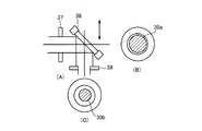
図8,図9は、図5に代わる受光部のさらに別の例を示す、それぞれ、光学フィルタが正常位置にあるとき、および位置ずれを生じているときの、光学系(A)、透過測定光束(B)、反射測定光束(C)を示す図である。 FIGS. 8 and 9 show still another example of the light receiving unit in place of FIG. 5. The optical system (A) and the transmission measurement when the optical filter is in the normal position and when the positional deviation occurs, respectively. It is a figure which shows a light beam (B) and a reflected measurement light beam (C).
図8,図9では、光学フィルタとして、波長によって反射光と透過光とに分離するダイクロイックミラー36が採用されており、そのダイクロイックミラー36の入射側にアパーチャ37が配置されるとともに、そのダイクロイックミラー36の反射側にもアパーチャ38が配置されている。
8 and 9, a
ダイクロイックミラー36は切替式となっており、図9に示すように位置ずれを生じるおそれがある。
The
この図8,図9に示す光学系の場合、ダイクロイックミラー36の透過測定光束30aはダイクロイックミラー36の入射側に配置されたアパーチャ37で規制され、ダイクロイックミラー36の反射側測定光束30bは、ダイクロイックミラー36の反射側に配置されたアパーチャ38で規制されている。ここに示す例では、ダイクロイックミラー36の透過側光束30aよりも反射測定光束30bの方が細径の光束に制限されているが、透過測定光束30aおよび反射測定光束30bのいずれも、ダイクロイックミラー35に位置ずれがあっても、そのダイクロイックミラー36の枠に光束が掛かることはなく、安定した測定が行われる。
In the case of the optical systems shown in FIGS. 8 and 9, the transmitted
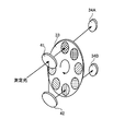
図10は、ターレット式のフィルタ板を示す図、図11,図12は、受光部の、さらに異なる光学系の例を示す図である。 FIG. 10 is a diagram showing a turret type filter plate, and FIGS. 11 and 12 are diagrams showing examples of further different optical systems of the light receiving section.
図10に示すフィルタ板33は、複数の光学フィルタ32A,32B,…,32Nが円状に配置されており、矢印方向に、光学フィルタ32A,32B,…,32Nの配列ピッチ単位で回転可能となっている。このフィルタ板33に1,2,3,4の番号が付されているがこれらの番号の意味については後述する。
The
図11,図12に示すように、キュベット20を透過してきた測定光は、ハーフミラー41により透過測定光と反射測定光とに分割され、そのうちの反射測定光はさらにミラー42で反射される。ハーフミラー41の透過測定光は、フィルタ板33に配列された複数の光学フィルタ32A,32B,…,32Nのうちのいずれか1つの光学フィルタを通過して光検出器34Aに入射する。一方、ハーフミラー41の反射測定光は、さらにミラー42で反射した後、フィルタ板33に配列された複数の光学フィルタ32A,32B,…,32Nのうちの別の1つの光学フィルタを通過して光検出器34Bに入射する。ここで、ハーフミラー41の透過測定光と反射測定光は、図10に示すフィルタ板33に配列された複数の光学フィルタ32A,32B…,32Nのうちの同じ番号を付した光学フィルタに入射し、2つの光検出器34A,34Bで、それら2枚の同番号が付された光学フィルタを通過することにより抽出された2つの波長の成分の各光量が測定される。したがって、この図11,図12に示す光学系を採用すると、2つの波長について同時に測定することができ、測定の高速化が実現する。
As shown in FIGS. 11 and 12, the measurement light transmitted through the
尚、図10に示すフィルタ板33には、番号4番を付した光学フィルタは1つのみであるが、これは、その光学フィルタにより出力される波長の光を測定する必要のある検体の場合はその1つの波長の光のみ測定すればよく、2つの波長の光を測定する必要はないからである。
Note that the
図13は、フィルタ板の他の例を示す図である。 FIG. 13 is a diagram illustrating another example of the filter plate.
この図13に示すフィルタ板43には、複数の光学フィルタ44A,44B,…,44Nが直線状に配置されている。このフィルタ板43の場合、光学フィルタ42A,42B,…,42Nの配列方向に移動することにより、測定光が通過する光学フィルタが切り替えられる。このように、フィルタ板は、図10に示すようなターレット式のものには限られない。
A plurality of
なお、本実施の形態では、測定容器をキュベット20としているが、これに限定されるものではなく、試験管等で光透過性の容器であれば適用が可能である。
In the present embodiment, the
また、本実施の形態では、開口部としてのアパーチャ16等は板状であるが、これに限定されるものではなく、開口を有し余分な光を遮蔽できればよく筒状等であっても適用が可能である。 In the present embodiment, the aperture 16 as the opening is plate-shaped, but the present invention is not limited to this, and may be applied to a cylindrical shape as long as it has an opening and can shield excess light. Is possible.
さらにまた、本実施の形態では、試薬は液体で分注しているとしているが、これに限定されるものではなく、試薬は粉末状であっても、あらかじめキュベット20内に入れられてあっても適用が可能である。
Furthermore, in this embodiment, it is assumed that the reagent is dispensed as a liquid. However, the present invention is not limited to this, and the reagent is put in the
11 ランプ
12 ランプハウス
13 第1レンズ
14,15,16 アパーチャ
17 第2レンズ
20 キュベット
30 測定光束
31 レンズ
32,32A,32B,…,32N 光学フィルタ
33 フィルタ板
34,34A,34B 光検出器
35 アパーチャ
36 ダイクロイックミラー
37,38 アパーチャ
41 ハーフミラー
42 ミラー
43 フィルタ板
44A,44B,…,44N 光学フィルタ
DESCRIPTION OF
Claims (3)
ランプと、
前記ランプを収容する、前方に開口したランプハウスと、
前記ランプハウスの開口近傍に配置され、前記ランプからの光を該測定点に導く第1レンズと、
前記第1レンズから出射した光の光束を規制する開口部と、
前記開口部を前記測定点近傍に結像する第2レンズと、
測定容器を透過した測定光を受光する受光部とを備えたことを特徴とする生化学分析装置。 A biochemical analyzer that contains a liquid mixture of a sample and a reagent, irradiates measurement light on a measurement container at a predetermined measurement point, and detects the measurement light transmitted through the measurement container, thereby performing biochemical analysis of the sample In
A lamp,
A lamp house that houses the lamp and opens forward;
A first lens disposed near the opening of the lamp house and guiding light from the lamp to the measurement point;
An opening that regulates the luminous flux of light emitted from the first lens;
A second lens that forms an image of the opening in the vicinity of the measurement point;
A biochemical analyzer, comprising: a light receiving portion that receives measurement light transmitted through the measurement container.
前記測定容器に測定光を照射する照射部と、
前記測定点を通過した測定光の光路に切替自在に進出して、測定光の中から所望の波長の光を抽出する光学素子と、
前記光学素子の前もしくは後に配置され、測定光の通過領域を規制する開口部と、
前記光学素子および前記開口部の双方を経由した後の測定光を検出する検出器とを備えたことを特徴とする生化学分析装置。 A biochemical analyzer that contains a liquid mixture of a sample and a reagent, irradiates measurement light on a measurement container at a predetermined measurement point, and detects the measurement light transmitted through the measurement container, thereby performing biochemical analysis of the sample In
An irradiation unit for irradiating the measurement container with measurement light;
An optical element that switches over to the optical path of the measurement light that has passed through the measurement point and extracts light of a desired wavelength from the measurement light;
An opening that is disposed before or after the optical element and restricts the passage region of the measurement light;
A biochemical analyzer comprising: a detector for detecting measurement light after passing through both the optical element and the opening.
前記測定容器に測定光を照射する照射部と、
複数の光学フィルタが配列されて一体的に移動することにより該複数の光学フィルタの切替えを行なうフィルタ板と、
前記測定点を通過した測定光を複数光束の測定光に分割して、該複数光束の測定光をそれぞれ異なる光学フィルタに導く光束分割光学系と、
前記フィルタ板を経由した後の複数光束の測定光それぞれを検出する複数の検出器とを備えたことを特徴とする生化学分析装置。 A biochemical analyzer that contains a liquid mixture of a sample and a reagent, irradiates measurement light on a measurement container at a predetermined measurement point, and detects the measurement light transmitted through the measurement container, thereby performing biochemical analysis of the sample In
An irradiation unit for irradiating the measurement container with measurement light;
A filter plate for switching the plurality of optical filters by arranging and moving the plurality of optical filters integrally;
A light beam splitting optical system that divides the measurement light that has passed through the measurement point into measurement light beams of a plurality of light beams, and guides the measurement light beams of the plurality of light beams to different optical filters, and
A biochemical analyzer comprising: a plurality of detectors for detecting each of a plurality of measurement light beams after passing through the filter plate.
Priority Applications (1)
| Application Number | Priority Date | Filing Date | Title |
|---|---|---|---|
| JP2004102747A JP2005291726A (en) | 2004-03-31 | 2004-03-31 | Biochemical analyzer |
Applications Claiming Priority (1)
| Application Number | Priority Date | Filing Date | Title |
|---|---|---|---|
| JP2004102747A JP2005291726A (en) | 2004-03-31 | 2004-03-31 | Biochemical analyzer |
Publications (1)
| Publication Number | Publication Date |
|---|---|
| JP2005291726A true JP2005291726A (en) | 2005-10-20 |
Family
ID=35324839
Family Applications (1)
| Application Number | Title | Priority Date | Filing Date |
|---|---|---|---|
| JP2004102747A Withdrawn JP2005291726A (en) | 2004-03-31 | 2004-03-31 | Biochemical analyzer |
Country Status (1)
| Country | Link |
|---|---|
| JP (1) | JP2005291726A (en) |
Cited By (6)
| Publication number | Priority date | Publication date | Assignee | Title |
|---|---|---|---|---|
| WO2009028064A1 (en) * | 2007-08-30 | 2009-03-05 | Shimadzu Corporation | Spectrophotometer |
| WO2010116237A1 (en) * | 2009-04-08 | 2010-10-14 | Amit Bhatnagar | Apparatus for determining optical density of liquid sample |
| CN102216744A (en) * | 2008-11-18 | 2011-10-12 | 皇家飞利浦电子股份有限公司 | filter wheel spectrometer |
| CN102384889A (en) * | 2011-08-03 | 2012-03-21 | 长春迪瑞医疗科技股份有限公司 | Integrating spherical optical system of automatic fecal occult blood analyzer |
| JP2012145429A (en) * | 2011-01-12 | 2012-08-02 | Toshiba Corp | Analysis equipment |
| CN103499525A (en) * | 2013-09-03 | 2014-01-08 | 冯晓均 | Blood sample biochemical quantitative detection device |
-
2004
- 2004-03-31 JP JP2004102747A patent/JP2005291726A/en not_active Withdrawn
Cited By (9)
| Publication number | Priority date | Publication date | Assignee | Title |
|---|---|---|---|---|
| WO2009028064A1 (en) * | 2007-08-30 | 2009-03-05 | Shimadzu Corporation | Spectrophotometer |
| CN102216744A (en) * | 2008-11-18 | 2011-10-12 | 皇家飞利浦电子股份有限公司 | filter wheel spectrometer |
| JP2012509493A (en) * | 2008-11-18 | 2012-04-19 | コーニンクレッカ フィリップス エレクトロニクス エヌ ヴィ | Filter wheel spectrometer |
| US8937720B2 (en) | 2008-11-18 | 2015-01-20 | Koninklijkle Philips N.V. | Filter wheel spectrometer |
| WO2010116237A1 (en) * | 2009-04-08 | 2010-10-14 | Amit Bhatnagar | Apparatus for determining optical density of liquid sample |
| JP2012145429A (en) * | 2011-01-12 | 2012-08-02 | Toshiba Corp | Analysis equipment |
| US9651478B2 (en) | 2011-01-12 | 2017-05-16 | Toshiba Medical Systems Corporation | Analyzer |
| CN102384889A (en) * | 2011-08-03 | 2012-03-21 | 长春迪瑞医疗科技股份有限公司 | Integrating spherical optical system of automatic fecal occult blood analyzer |
| CN103499525A (en) * | 2013-09-03 | 2014-01-08 | 冯晓均 | Blood sample biochemical quantitative detection device |
Similar Documents
| Publication | Publication Date | Title |
|---|---|---|
| US4774055A (en) | Automatic analysis apparatus | |
| US10670454B2 (en) | System for optically monitoring operating conditions in a sample analyzing apparatus | |
| US7842509B2 (en) | Blood analyzer and blood analyzing method | |
| JP7019300B2 (en) | Optical equipment for analysis of microwells | |
| JP3524419B2 (en) | Absorbance measurement device | |
| JP2016503900A (en) | Optical measurement apparatus and method for analyzing samples contained in droplets | |
| JPS63286750A (en) | Detector assembly | |
| JPH0619351B2 (en) | Latex agglutination reaction measuring device | |
| EP2466292B1 (en) | System for performing scattering and absorbance assays | |
| JP2007322324A (en) | Analyzer | |
| JP7300826B2 (en) | Analysis device and analysis method | |
| CN109477795B (en) | Methods and systems for optics-based measurements with selectable excitation light paths | |
| US20150110674A1 (en) | Coloration analysis device | |
| EP3336495B1 (en) | Characterizing the emission properties of samples | |
| JP2022133528A (en) | automatic analyzer | |
| RU2060499C1 (en) | Device determining number of somatic cells in milk | |
| JP2005049109A (en) | Chemical analyzer | |
| JPS62217163A (en) | Automatic analyzing instrument | |
| JPH11316189A (en) | Photometer for automatic analyzer | |
| JP2000009740A (en) | Blood text device and dispensation device | |
| JP2015175667A (en) | Automatic analysis apparatus | |
| JP2017083296A (en) | Automatic analyzer | |
| CN115280155A (en) | Sample analysis device and method | |
| JPS62145166A (en) | Automatic chemical analyzer | |
| KR20100017098A (en) | Automated analyzer |
Legal Events
| Date | Code | Title | Description |
|---|---|---|---|
| A300 | Withdrawal of application because of no request for examination |
Free format text: JAPANESE INTERMEDIATE CODE: A300 Effective date: 20070605 |