JP2005291741A - Infrared gas analyzer - Google Patents
Infrared gas analyzer Download PDFInfo
- Publication number
- JP2005291741A JP2005291741A JP2004103074A JP2004103074A JP2005291741A JP 2005291741 A JP2005291741 A JP 2005291741A JP 2004103074 A JP2004103074 A JP 2004103074A JP 2004103074 A JP2004103074 A JP 2004103074A JP 2005291741 A JP2005291741 A JP 2005291741A
- Authority
- JP
- Japan
- Prior art keywords
- detector
- gas
- infrared
- acceleration
- actuator
- Prior art date
- Legal status (The legal status is an assumption and is not a legal conclusion. Google has not performed a legal analysis and makes no representation as to the accuracy of the status listed.)
- Pending
Links
Images
Landscapes
- Investigating Or Analysing Materials By Optical Means (AREA)
Abstract
【課題】 耐振性が向上された赤外線ガス分析計を実現する。
【解決手段】 赤外線光がそれぞれ透過する測定セルと基準セルと、測定成分が含まれるガスが充填され前記測定セルと前記基準セルとをそれぞれ透過した光が投射され透過する光量の差により発生する前記ガスの微少流量からガス濃度を検出する検出器とを具備する赤外線ガス分析計において、前記検出器に設けられ検出器のガスの流通方向の振動加速度を検出する加速度センサと、前記検出器を前記ガス流通方向に駆動するアクチュエータと、前記加速度センサで検出される加速度がゼロになるよう前記アクチュエータを駆動制御する制御部とを具備したことを特徴とする赤外線ガス分析計である。
【選択図】 図1
PROBLEM TO BE SOLVED: To realize an infrared gas analyzer having improved vibration resistance.
SOLUTION: A measurement cell and a reference cell through which infrared light is transmitted respectively, and a difference in the amount of light that is filled and filled with a gas containing a measurement component and is transmitted through the measurement cell and the reference cell. An infrared gas analyzer comprising a detector that detects a gas concentration from a minute flow rate of the gas, an acceleration sensor that is provided in the detector and detects vibration acceleration in a gas flow direction of the detector, and the detector An infrared gas analyzer comprising: an actuator that drives in the gas flow direction; and a controller that drives and controls the actuator so that the acceleration detected by the acceleration sensor becomes zero.
[Selection] Figure 1
Description
本発明は、赤外光を利用してガス濃度を測定する赤外線ガス分析計に関し、特にその耐振性が向上された赤外線ガス分析計に関するものである。 The present invention relates to an infrared gas analyzer for measuring a gas concentration using infrared light, and more particularly to an infrared gas analyzer having improved vibration resistance.
赤外線ガス分析計に関連する先行技術文献としては次のようなものがある。 Prior art documents related to the infrared gas analyzer include the following.
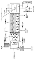
図2は、従来より一般に使用されている従来例の構成説明図である。
図において、赤外線光源1から発せられた赤外光が分配セル2により2つに分割され、それぞれ基準セル3、測定セル4に入射する。
基準セル3には不活性ガスなど測定対象成分を含まないガスが充填されている。
測定セル4に測定試料が流通する。
FIG. 2 is a diagram illustrating the configuration of a conventional example that is generally used.
In the figure, the infrared light emitted from the
The
A measurement sample flows through the measurement cell 4.
分配セル2で2つに分けられた赤外光は、測定セル4でのみ測定対象成分に起因する吸収を受け検出器5に到達する。
検出器5は基準セル3からの光と測定セル4からの光を受ける2室(基準側室51、試料側室52)からなっており、その2室が流通路53でつながる構造をしており、その流通路53にガスの行き来を検出するためのサーマルフローセンサ54が取り付けられている。
The infrared light divided into two by the
The detector 5 is composed of two chambers (a reference side chamber 51 and a sample side chamber 52) that receive light from the
検出器5内には測定対象と同じ成分を含むガスが充填されており、基準セル3、測定セル4からの赤外光が照射されると、測定対象成分のガスが赤外光を吸収するためその中でガスが膨張する。
測定セル4内の測定試料に測定対象成分が多く含まれると、赤外光はそこで多くが吸収されるため、検出器5では基準側室51に多くの赤外光が照射され、よりガスが膨張する。
The detector 5 is filled with a gas containing the same component as the measurement target, and when the infrared light from the
If the measurement sample in the measurement cell 4 contains a large amount of measurement target component, a large amount of infrared light is absorbed there. Therefore, the detector 5 irradiates the reference side chamber 51 with a lot of infrared light, and the gas expands more. To do.
赤外光は回転セクタ6で遮断、照射を繰り返しており、遮断されたときは基準側室51、試料側室52とも赤外光が照射されないのでガスは膨張せず、赤外光が照射されると検出器の試料側室52には測定セル4内の測定対象成分濃度に応じた赤外光が、基準側室51には基準セル3を透過した赤外光が照射される。
The infrared light is repeatedly blocked and irradiated by the rotating sector 6, and when the infrared light is blocked, neither the reference side chamber 51 nor the sample side chamber 52 is irradiated with infrared light, so that the gas does not expand and is irradiated with infrared light. The sample side chamber 52 of the detector is irradiated with infrared light corresponding to the concentration of the measurement target component in the measurement cell 4, and the reference side chamber 51 is irradiated with infrared light transmitted through the
基準側室51は、ほぼ一定の赤外光が照射され、試料側室52には試料中の測定対象成分濃度に応じた赤外光が照射されるため、試料中の測定対象成分の濃度に応じて両室の間に差圧が生じ、両室間の間に設けられた流通路53をガスが行き来することとなる。
そのガスの挙動をサーマルフローセンサ54で検出し、交流電圧増幅器7で増幅し、濃度信号8として出力する。
The reference side chamber 51 is irradiated with substantially constant infrared light, and the sample side chamber 52 is irradiated with infrared light corresponding to the concentration of the measurement target component in the sample. A differential pressure is generated between the two chambers, and the gas flows back and forth through the flow passage 53 provided between the two chambers.
The behavior of the gas is detected by the thermal flow sensor 54, amplified by the AC voltage amplifier 7, and output as the concentration signal 8.
今後、赤外ガス分析計においても、環境計測用など小型化への要求が高く、そのためにはフローセンサ54を高感度化し、ガスの微少流を高感度で検出できるよう検討が行われている。
しかしながらこのような構成においては、装置に振動が加わると、検出器5内のガスは慣性によりその場にとどまろうとするため、サーマルフローセンサ54と検出器5内のガスの間に相対的にガス流が生じることになり、その成分がノイズとして検出される。
In the future, there is a high demand for downsizing of infrared gas analyzers, such as for environmental measurement. To that end, studies are being made to increase the sensitivity of the flow sensor 54 and detect a minute gas flow with high sensitivity. .
However, in such a configuration, when vibration is applied to the apparatus, the gas in the detector 5 tends to stay in place due to inertia, so that a relative gas is present between the thermal flow sensor 54 and the gas in the detector 5. A flow is generated, and the component is detected as noise.
その影響の大きさは信号成分(濃度によりガス流)の検出器5内のガスの移動速度と振動に起因するガス流の速度の比となるため、耐振性を向上するには、信号成分を大きくする、つまり測定セル4・基準セル3の長さを長くし、試料セル内で赤外光が吸収される量を多くするしかなく、フローセンサ54を高感度化しても、小型化の実現は困難であった。
Since the magnitude of the influence is the ratio of the gas flow velocity in the detector 5 of the signal component (gas flow depending on the concentration) and the gas flow velocity caused by vibration, the signal component is used to improve the vibration resistance. There is no choice but to increase the length of the measurement cell 4 and the
本発明の目的は、上記の課題を解決するもので、検出器の耐振性を向上し、小型化しても十分な耐振性のある赤外ガス分析計を提供することを目的とする。 SUMMARY OF THE INVENTION An object of the present invention is to solve the above-described problems, and an object of the present invention is to provide an infrared gas analyzer that improves the vibration resistance of a detector and has sufficient vibration resistance even if it is downsized.
このような課題を達成するために、本発明では、請求項1の赤外線ガス分析計においては、
赤外線光がそれぞれ透過する測定セルと基準セルと、測定成分が含まれるガスが充填され前記測定セルと前記基準セルとをそれぞれ透過した光が投射され透過する光量の差により発生する前記ガスの微少流量からガス濃度を検出する検出器とを具備する赤外線ガス分析計において、
前記検出器に設けられ検出器のガスの流通方向の振動加速度を検出する加速度センサと、前記検出器を前記ガス流通方向に駆動するアクチュエータと、前記加速度センサで検出される加速度がゼロになるよう前記アクチュエータを駆動制御する制御部とを具備したことを特徴とする。
In order to achieve such a subject, in the present invention, in the infrared gas analyzer of
A measurement cell and a reference cell through which infrared light passes, and a small amount of the gas generated by a difference in the amount of light that is filled with a gas containing a measurement component and is transmitted through the measurement cell and the reference cell. In an infrared gas analyzer comprising a detector for detecting a gas concentration from a flow rate,
An acceleration sensor provided in the detector for detecting vibration acceleration in the gas flow direction of the detector, an actuator for driving the detector in the gas flow direction, and an acceleration detected by the acceleration sensor to be zero. And a control unit for driving and controlling the actuator.
本発明の請求項2においては、請求項1記載の赤外線ガス分析計において、
前記検出器とこの検出器の取付け部分との相対変位を検出する変位センサと、この変位センサの信号に基づき前記相対変位がゼロとなるように前記アクチュエータを駆動制御するとともにその制御帯域が前記加速度センサに基ずく制御帯域より低い周波数で制御する制御部とを具備したことを特徴とする。
In
A displacement sensor that detects a relative displacement between the detector and a mounting portion of the detector, and the actuator is driven and controlled based on a signal of the displacement sensor so that the relative displacement becomes zero, and a control band thereof is the acceleration. And a control unit that controls at a frequency lower than the control band based on the sensor.
以上説明したように、本発明の請求項1によれば、次のような効果がある。
検出器における濃度信号の検出に使用されるガス流と同方向の振動加速度がゼロになるように検出器の振動を制御するように構成したため、濃度検出の振動に起因するノイズ成分が低減できるため、耐振性の向上が実現出来る赤外線ガス分析計が得られる。
また、濃度に起因するガス流が微少になっても、フローセンサを高感度化することで検出できるため、小型の赤外線ガス分析計が得られる。
As described above, according to the first aspect of the present invention, the following effects can be obtained.
Since the vibration of the detector is controlled so that the vibration acceleration in the same direction as the gas flow used for detecting the concentration signal in the detector becomes zero, the noise component caused by the vibration of the concentration detection can be reduced. Thus, an infrared gas analyzer capable of improving vibration resistance can be obtained.
In addition, even if the gas flow due to the concentration becomes minute, it can be detected by increasing the sensitivity of the flow sensor, so that a small infrared gas analyzer can be obtained.
本発明の請求項2によれば、次のような効果がある。
検出器とこの検出器の取付け部分との相対変位を検出する変位センサと、この変位センサの信号に基づき相対変位がゼロとなるようにアクチュエータを駆動制御するとともにその制御帯域が加速度センサに基ずく制御帯域より低い周波数で制御する制御部とが設けられたので、加速度のみを基に制御した場合に比べ、取付け部分と検出器のずれが生じないため、安定した測定が行える赤外線ガス分析計が得られる。
According to
A displacement sensor that detects the relative displacement between the detector and the mounting portion of the detector, and the actuator is driven and controlled so that the relative displacement becomes zero based on the signal of the displacement sensor, and the control band is based on the acceleration sensor. Since there is a control unit that controls at a frequency lower than the control band, there is no displacement between the mounting part and the detector compared to control based only on acceleration, so an infrared gas analyzer that can perform stable measurement is can get.
以下本発明を図面を用いて詳細に説明する。
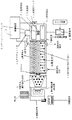
図1は本発明の一実施例の要部構成説明図である。
加速度センサ11は、検出器5に設けられ、検出器5のガスの流通方向の振動加速度を検出する。
アクチュエータ12は、検出器5をガス流通方向に駆動する。
Hereinafter, the present invention will be described in detail with reference to the drawings.
FIG. 1 is an explanatory view of the main part configuration of an embodiment of the present invention.
The acceleration sensor 11 is provided in the detector 5 and detects vibration acceleration in the gas flow direction of the detector 5.
The actuator 12 drives the detector 5 in the gas flow direction.
制御部13は、加速度センサ11で検出される加速度がゼロになるよう、アクチュエータ12を駆動制御する。
変位センサ14は、検出器5とこの検出器の取付け部分15との相対変位を検出する。
また、制御部13は、変位センサ14の信号に基づき、相対変位がゼロとなるように、アクチュエータ12を駆動制御するとともに、その制御帯域が加速度センサ11に基ずく制御帯域より低い周波数で制御する。
The control unit 13 drives and controls the actuator 12 so that the acceleration detected by the acceleration sensor 11 becomes zero.
The displacement sensor 14 detects a relative displacement between the detector 5 and the mounting portion 15 of the detector.
Further, the control unit 13 drives and controls the actuator 12 based on the signal from the displacement sensor 14 so that the relative displacement becomes zero, and the control band is controlled at a frequency lower than the control band based on the acceleration sensor 11. .
以上の構成において、検出器5に取り付けられた加速度センサ11にて検出器5の振動加速度を検出する。
その出力は、制御部13に入力され、制御部13にてその加速度がゼロになるようにアクチュエータ12を駆動して、検出器5の振動を制御する。
In the above configuration, the vibration acceleration of the detector 5 is detected by the acceleration sensor 11 attached to the detector 5.
The output is input to the control unit 13, and the actuator 12 is driven by the control unit 13 so that the acceleration becomes zero, thereby controlling the vibration of the detector 5.
また、変位センサ14にて装置のベースとなる部分15と検出器5の相対変位を検出する。
その出力もまた、制御部13に入力される。
制御部13では、加速度センサ11の出力に基ずく振動制御より十分遅い周波数帯域で、その相対変位がゼロになるようにアクチュエータ12を駆動し検出器5の位置を制御する。
Further, the displacement sensor 14 detects the relative displacement between the portion 15 serving as the base of the apparatus and the detector 5.
The output is also input to the control unit 13.
The controller 13 controls the position of the detector 5 by driving the actuator 12 so that the relative displacement becomes zero in a frequency band sufficiently slower than the vibration control based on the output of the acceleration sensor 11.
この結果、
検出器5における濃度信号の検出に使用されるガス流と同方向の振動加速度がゼロになるように検出器5の振動を制御するように構成したため、濃度検出の振動に起因するノイズ成分が低減できるため、耐振性の向上が実現出来る赤外線ガス分析計が得られる。
As a result,
Since the vibration of the detector 5 is controlled so that the vibration acceleration in the same direction as the gas flow used for detecting the concentration signal in the detector 5 becomes zero, the noise component caused by the vibration of the concentration detection is reduced. Therefore, an infrared gas analyzer capable of improving vibration resistance can be obtained.
また、濃度に起因するガス流が微少になっても、フローセンサ54を高感度化することで検出できるため、小型の赤外線ガス分析計が得られる。
また、取付け部分15と検出器5の相対変位を検出し、11加速度センサの出力に基ずく振動制御より十分遅い周波数で、相対変位がゼロになるように制御するように構成したため、加速度のみを基に制御した場合に比べ、取付け部分と検出器のずれが生じないため、安定した測定が行える赤外線ガス分析計が得られる。
In addition, even if the gas flow due to the concentration becomes small, it can be detected by increasing the sensitivity of the flow sensor 54, so that a small infrared gas analyzer can be obtained.
In addition, since the relative displacement between the attachment portion 15 and the detector 5 is detected and the relative displacement is controlled to be zero at a frequency sufficiently slower than the vibration control based on the output of the 11 acceleration sensor, only the acceleration is detected. Compared to the control based on the base, the mounting portion and the detector are not displaced, so an infrared gas analyzer capable of performing stable measurement can be obtained.
なお、以上の説明は、本発明の説明および例示を目的として特定の好適な実施例を示したに過ぎない。
したがって本発明は、上記実施例に限定されることなく、その本質から逸脱しない範囲で更に多くの変更、変形をも含むものである。
The above description merely shows a specific preferred embodiment for the purpose of explanation and illustration of the present invention.
Therefore, the present invention is not limited to the above-described embodiments, and includes many changes and modifications without departing from the essence thereof.
1 赤外線光源
2 反射部
3 基準セル
4 測定セル
5 検出器
51 基準側室
52 試料側室
53 流通路
54 サーマルフローセンサ
6 回転セクタ
7 交流電圧増幅器
8 濃度信号
11 加速度センサ
12 アクチュエータ
13 制御部
14 変位センサ
15 検出器の取付け部分
DESCRIPTION OF
Claims (2)
前記検出器に設けられ検出器のガスの流通方向の振動加速度を検出する加速度センサと、
前記検出器を前記ガス流通方向に駆動するアクチュエータと、
前記加速度センサで検出される加速度がゼロになるよう前記アクチュエータを駆動制御する制御部と
を具備したことを特徴とする赤外線ガス分析計。 A measurement cell and a reference cell through which infrared light passes, and a small amount of the gas generated by a difference in the amount of light that is filled with a gas containing a measurement component and is transmitted through the measurement cell and the reference cell. In an infrared gas analyzer comprising a detector for detecting a gas concentration from a flow rate,
An acceleration sensor that is provided in the detector and detects vibration acceleration in a gas flow direction of the detector;
An actuator for driving the detector in the gas flow direction;
An infrared gas analyzer comprising: a control unit that drives and controls the actuator so that the acceleration detected by the acceleration sensor becomes zero.
この変位センサの信号に基づき前記相対変位がゼロとなるように前記アクチュエータを駆動制御するとともにその制御帯域が前記加速度センサに基ずく制御帯域より低い周波数で制御する制御部と
を具備したことを特徴とする請求項1記載の赤外線ガス分析計。
A displacement sensor for detecting a relative displacement between the detector and a mounting portion of the detector;
A control unit that controls the drive of the actuator so that the relative displacement becomes zero based on a signal of the displacement sensor, and controls the control band at a frequency lower than the control band based on the acceleration sensor. The infrared gas analyzer according to claim 1.
Priority Applications (1)
| Application Number | Priority Date | Filing Date | Title |
|---|---|---|---|
| JP2004103074A JP2005291741A (en) | 2004-03-31 | 2004-03-31 | Infrared gas analyzer |
Applications Claiming Priority (1)
| Application Number | Priority Date | Filing Date | Title |
|---|---|---|---|
| JP2004103074A JP2005291741A (en) | 2004-03-31 | 2004-03-31 | Infrared gas analyzer |
Publications (1)
| Publication Number | Publication Date |
|---|---|
| JP2005291741A true JP2005291741A (en) | 2005-10-20 |
Family
ID=35324852
Family Applications (1)
| Application Number | Title | Priority Date | Filing Date |
|---|---|---|---|
| JP2004103074A Pending JP2005291741A (en) | 2004-03-31 | 2004-03-31 | Infrared gas analyzer |
Country Status (1)
| Country | Link |
|---|---|
| JP (1) | JP2005291741A (en) |
Cited By (2)
| Publication number | Priority date | Publication date | Assignee | Title |
|---|---|---|---|---|
| JP2007240239A (en) * | 2006-03-07 | 2007-09-20 | Yokogawa Electric Corp | Infrared gas analyzer |
| US8089046B2 (en) * | 2008-09-19 | 2012-01-03 | Applied Materials, Inc. | Method and apparatus for calibrating mass flow controllers |
-
2004
- 2004-03-31 JP JP2004103074A patent/JP2005291741A/en active Pending
Cited By (2)
| Publication number | Priority date | Publication date | Assignee | Title |
|---|---|---|---|---|
| JP2007240239A (en) * | 2006-03-07 | 2007-09-20 | Yokogawa Electric Corp | Infrared gas analyzer |
| US8089046B2 (en) * | 2008-09-19 | 2012-01-03 | Applied Materials, Inc. | Method and apparatus for calibrating mass flow controllers |
Similar Documents
| Publication | Publication Date | Title |
|---|---|---|
| JP5410292B2 (en) | SAMPLE DETECTING DEVICE AND MEASURING DEVICE HAVING THE SAME | |
| JP2016218033A (en) | Compound environmental sensor | |
| AU2001289914A1 (en) | Image sensor device, apparatus and method for optical measurements | |
| EP1850113A2 (en) | Dynamic measured-value filter for a gas sensor arrangement | |
| CN104655587A (en) | Extra-high sensitive gas absorption spectrum measuring system and method based on MEMS | |
| WO2024207640A1 (en) | Counting method based particle size monitor for biological aerosol particles | |
| CN110160988A (en) | Spectroscopy apparatus | |
| JP5525471B2 (en) | Condensation detection method and apparatus | |
| US8241919B2 (en) | Gas pulse generator for baseline drift correction and related system and method | |
| JP7042742B2 (en) | Wide range gas detection method using infrared gas detector | |
| JP2005292009A (en) | Infrared gas detector and detection method | |
| JP4411599B2 (en) | Infrared gas analyzer and infrared gas analysis method | |
| JP4577177B2 (en) | Differential refractive index detector and adjustment method thereof | |
| JP2009014465A (en) | Infrared gas analyzer | |
| JPH06249779A (en) | Gas analyzer | |
| JP2007010484A (en) | Gas detector and infrared gas analyzer | |
| JPS61250544A (en) | Infrared gas analyzer | |
| KR20100135060A (en) | Optical gas sensor and gas concentration analysis device including the same | |
| JP2006329913A (en) | Infrared gas analyzer | |
| JP2007501390A (en) | Photoacoustic gas sensor using diffusion | |
| JPS6350739A (en) | Gas detector | |
| JP2003083889A (en) | Infrared analyzer | |
| JP4666252B2 (en) | Hot wire flow sensor and infrared gas analyzer | |
| JP2007240239A (en) | Infrared gas analyzer | |
| JP4793413B2 (en) | Differential refractive index detector |