JP2005291788A - Vehicle object recognition device - Google Patents
Vehicle object recognition device Download PDFInfo
- Publication number
- JP2005291788A JP2005291788A JP2004104120A JP2004104120A JP2005291788A JP 2005291788 A JP2005291788 A JP 2005291788A JP 2004104120 A JP2004104120 A JP 2004104120A JP 2004104120 A JP2004104120 A JP 2004104120A JP 2005291788 A JP2005291788 A JP 2005291788A
- Authority
- JP
- Japan
- Prior art keywords
- vehicle
- recognition
- range
- transmission wave
- surface number
- Prior art date
- Legal status (The legal status is an assumption and is not a legal conclusion. Google has not performed a legal analysis and makes no representation as to the accuracy of the status listed.)
- Pending
Links
Images


Classifications
-
- G—PHYSICS
- G01—MEASURING; TESTING
- G01S—RADIO DIRECTION-FINDING; RADIO NAVIGATION; DETERMINING DISTANCE OR VELOCITY BY USE OF RADIO WAVES; LOCATING OR PRESENCE-DETECTING BY USE OF THE REFLECTION OR RERADIATION OF RADIO WAVES; ANALOGOUS ARRANGEMENTS USING OTHER WAVES
- G01S7/00—Details of systems according to groups G01S13/00, G01S15/00, G01S17/00
- G01S7/48—Details of systems according to groups G01S13/00, G01S15/00, G01S17/00 of systems according to group G01S17/00
- G01S7/497—Means for monitoring or calibrating
- G01S7/4972—Alignment of sensor
-
- G—PHYSICS
- G01—MEASURING; TESTING
- G01S—RADIO DIRECTION-FINDING; RADIO NAVIGATION; DETERMINING DISTANCE OR VELOCITY BY USE OF RADIO WAVES; LOCATING OR PRESENCE-DETECTING BY USE OF THE REFLECTION OR RERADIATION OF RADIO WAVES; ANALOGOUS ARRANGEMENTS USING OTHER WAVES
- G01S17/00—Systems using the reflection or reradiation of electromagnetic waves other than radio waves, e.g. lidar systems
- G01S17/88—Lidar systems specially adapted for specific applications
- G01S17/93—Lidar systems specially adapted for specific applications for anti-collision purposes
- G01S17/931—Lidar systems specially adapted for specific applications for anti-collision purposes of land vehicles
Landscapes
- Engineering & Computer Science (AREA)
- Physics & Mathematics (AREA)
- Computer Networks & Wireless Communication (AREA)
- General Physics & Mathematics (AREA)
- Radar, Positioning & Navigation (AREA)
- Remote Sensing (AREA)
- Electromagnetism (AREA)
- Traffic Control Systems (AREA)
- Optical Radar Systems And Details Thereof (AREA)
- Controls For Constant Speed Travelling (AREA)
- Instrument Panels (AREA)
- Radar Systems Or Details Thereof (AREA)
Abstract
【課題】障害物中の反射物体が高い位置にある場合においても、送信波をその反射物体に照射でき、正確な距離検出を行うことができる。
【解決手段】 低速状態もしくは近距離状態であることが検出された場合に、通常走行時の場合と比べて上方にレーザ光が照射されるようにする。例えば、ポリゴンミラーの各側面のうち認識使用範囲に相当するものが面番号4、5、6であったとすると、低速状態もしくは近距離状態のときには、その面番号を1つ減らし、認識使用範囲を面番号3、4、5に切り替える。これにより、トラック等と自車両との距離が近づいたとしても、レーザ光が上方に照射され、高い位置のリフレクタに当たるようにすることが可能となる。したがって、トラック等と自車両との距離が近づいて、レーザ光がリフレクタに当たらなくなり、突然距離検出が正確に行えなくなるという状態を防ぐことができる。
【選択図】 図16
Even when a reflecting object in an obstacle is at a high position, a transmission wave can be irradiated to the reflecting object, and accurate distance detection can be performed.
SOLUTION: When it is detected that the vehicle is in a low speed state or a short distance state, the laser beam is irradiated upward as compared with the case of normal traveling. For example, if the side numbers of the polygon mirror corresponding to the recognition usage range are surface numbers 4, 5, and 6, the surface number is reduced by one in the low speed state or the short distance state, and the recognition usage range is reduced. Switch to surface number 3, 4, 5. As a result, even when the distance between the truck or the like and the host vehicle is short, the laser beam is irradiated upward, and can hit the reflector at a high position. Therefore, it is possible to prevent a situation in which the distance between the truck and the own vehicle approaches and the laser light does not hit the reflector and the distance detection cannot be performed suddenly.
[Selection] FIG.
Description
本発明は、車幅方向及び高さ方向それぞれの所定角度範囲内に渡り送信波を照射し、その反射波に基づいて自車両の前方の物体を認識する車両用物体認識装置に関するものである。 The present invention relates to a vehicle object recognition device that irradiates a transmission wave over a predetermined angle range in each of a vehicle width direction and a height direction and recognizes an object ahead of the host vehicle based on the reflected wave.
従来より、車両に搭載される距離検出装置として、例えばレーザ光によって先行車等の障害物との距離を測定するもの(レーザレーダ)が知られている。この距離検出装置は、レーザダイオードを断続的に発光させて車両の前方に照射し、前方の障害物からの反射光をフォトセンサで検出し、発光時刻と受光時刻との時間差に基づいて、障害物までの距離を測定する。 2. Description of the Related Art Conventionally, as a distance detection device mounted on a vehicle, for example, a device (laser radar) that measures a distance from an obstacle such as a preceding vehicle using laser light is known. This distance detection device emits a laser diode intermittently to irradiate the front of the vehicle, detects reflected light from an obstacle ahead, and detects the obstacle based on the time difference between the light emission time and the light reception time. Measure the distance to the object.
具体的には、距離検出装置は、レーザ光を照射する発光部と、そのレーザ光を反射する六角錐台形状の回転可能なスキャンミラーとなるポリゴンミラーと、反射してきたレーザ光を受け取る受光部とを備えた構成となっている。このような構成により、発光部が照射したレーザ光をポリゴンミラーにて反射させて車両前方に導く。このとき、ポリゴンミラーを回転させ、ポリゴンミラーの各側面に発光部からのレーザ光が当たるようにすることで、ポリゴンミラーでのレーザ光の反射角度を調整し、車両前方の所定範囲にレーザ光がスキャンされるようにする。そして、例えば先行車両におけるリフレクタを障害物中の反射対象として、このリフレクタで反射したレーザ光を受光部で受け取ることで距離の測定を行うようにしている(例えば、特許文献1参照)。
従来の距離検出装置では、車両前方に向けて照射されるレーザ光は、例えば上下左右において所定の範囲でスキャンされるようになっている。このスキャン範囲は、距離検出装置による検出距離を考慮して決められており、例えば上下方向において4deg、左右方向において±18deg程度に設定される。 In the conventional distance detection device, the laser light emitted toward the front of the vehicle is scanned in a predetermined range, for example, vertically and horizontally. This scan range is determined in consideration of the detection distance by the distance detection device, and is set to, for example, about 4 deg in the vertical direction and about ± 18 deg in the horizontal direction.
しかしながら、このようなスキャン範囲とした場合、トラック等のように、車高が高く、リフレクタの設置位置が高い車両では、レーザ光が照射される範囲よりもリフレクタの設置位置の方が高くなってしまい、レーザ光が上手くリフレクタに当たらくなる。特に、車両におけるバンパーの下部のような低い位置に距離検出装置が装着されるような場合には、それが顕著になる。このため、トラック等と自車両との距離が近づいたときに、レーザ光がリフレクタに当たらなくなって、突然距離検出が行えなくなるという問題がある。 However, in such a scan range, in a vehicle having a high vehicle height and a high reflector installation position such as a truck, the reflector installation position is higher than the laser light irradiation range. As a result, the laser beam hits the reflector well. This is particularly noticeable when the distance detection device is mounted at a low position such as the lower part of the bumper in the vehicle. For this reason, there is a problem that when the distance between the truck or the like and the own vehicle approaches, the laser beam does not hit the reflector and the distance cannot be detected suddenly.
本発明は上記点に鑑みて、例えば車高が高い車等のように、障害物中の反射物体が高い位置にある場合においても、送信波をその反射物体に照射でき、正確な距離検出を行うことができる車両用物体認識装置を提供することを目的とする。 In view of the above points, the present invention can irradiate the reflected wave with the reflected object even when the reflected object in the obstacle is at a high position, such as a car with a high vehicle height, and can detect the distance accurately. An object of the present invention is to provide an object recognition device for a vehicle that can be performed.
上記目的を達成するため、請求項1に記載の発明では、車両の車速を検出する車速検出手段(47)と、車速検出手段によって検出された車速が所定車速よりも小さい低速状態のときに、認識使用範囲(93)の切り替えを行い、この切り替え前に設定されていた認識使用範囲よりも車両の上方に送信波が照射されるように、スキャン手段(73)にて照射可能な複数の角度範囲から新たな認識使用範囲を設定する認識使用範囲切替手段(200〜230)と、を備えていることを特徴としている。 In order to achieve the above object, according to the first aspect of the present invention, when the vehicle speed detecting means (47) for detecting the vehicle speed of the vehicle and the vehicle speed detected by the vehicle speed detecting means are in a low speed state smaller than a predetermined vehicle speed, A plurality of angles that can be irradiated by the scanning means (73) so that the recognition use range (93) is switched and the transmission wave is irradiated above the vehicle beyond the recognition use range set before the switch. And a recognition usage range switching means (200 to 230) for setting a new recognition usage range from the range.
このように、低速状態になったときには、先行車両との車間距離が短くなる可能性が高いものとして、認識使用範囲切替手段を用いて、切り替え前に設定されていた認識使用範囲よりも車両の上方に送信波が照射されるようにしている。このため、トラック等と自車両との距離が近づいたとしても、レーザ光が上方に照射され、高い位置のリフレクタに当たるようにすることが可能となる
したがって、トラック等と自車両との距離が近づいて、レーザ光がリフレクタに当たらなくなり、突然距離検出が正確に行えなくなるという状態を防ぐことができる。
Thus, when the vehicle enters a low speed state, it is highly likely that the inter-vehicle distance from the preceding vehicle is likely to be short, and the recognized use range switching means is used to detect the vehicle more than the recognized use range set before switching. A transmission wave is irradiated upward. For this reason, even if the distance between the truck or the like and the own vehicle approaches, it becomes possible to irradiate the laser beam upward and hit the reflector at a higher position. Therefore, the distance between the truck or the like and the own vehicle becomes closer. Thus, it is possible to prevent a situation where the laser beam does not hit the reflector and suddenly distance detection cannot be performed accurately.
請求項2および3に記載の発明では、認識手段によって認識された反射物体が先行車両であることを判定すると共に、先行車両までの車間距離(Z)を求める先行車判定手段(53)を有し、認識使用範囲切替手段は、先行車判定手段によって検出された先行車両までの車間距離が所定値よりも小さい近距離状態のときに、認識使用範囲の切り替えを行い、この切り替え以前に設定されていた認識使用範囲よりも車両の上方に送信波が照射されるように、スキャン手段にて照射可能な複数の角度範囲から新たな認識使用範囲を設定するようになっていることを特徴としている。 According to the second and third aspects of the present invention, it is determined that the reflecting object recognized by the recognition means is a preceding vehicle, and has a preceding vehicle determining means (53) for obtaining an inter-vehicle distance (Z) to the preceding vehicle. The recognition usage range switching means switches the recognition usage range when the inter-vehicle distance to the preceding vehicle detected by the preceding vehicle determination means is a short distance state smaller than a predetermined value, and is set before this switching. It is characterized in that a new recognition and use range is set from a plurality of angle ranges that can be irradiated by the scanning means so that the transmission wave is irradiated above the recognized use and use range. .
このように、自車両と先行車両との間の車間距離が所定値よりも短くなったときに、認識使用範囲を切り替えるようにしても良い。これにより、請求項1と同様の効果を得ることができる。
As described above, when the inter-vehicle distance between the host vehicle and the preceding vehicle becomes shorter than a predetermined value, the recognized use range may be switched. Thereby, the same effect as that of
請求項4に記載の発明は、スキャン手段として、面倒れ角が異なる複数の側面を有する多面ミラー、例えばポリゴンミラーなどが用いられる場合を示している。この場合、例えば、認識使用範囲設定手段は、多面ミラーの各側面の面倒れ角に応じた面番号を記憶し、多面ミラーの各側面のうち認識使用範囲に相当する面番号のもので送信波を反射させることにより、認識使用範囲における送信波の照射を行うように構成される。
The invention described in
したがって、認識使用範囲切替手段にて、多面ミラーの各側面のうち認識使用範囲設定手段に記憶された面番号のものよりも送信波が車両の上方に照射されるものの面番号を新たな認識使用範囲に相当する面番号とし、多面ミラーの各側面のうち切り替え後の面番号のもので送信波が照射されるようにする。 Therefore, the recognition / use range switching means newly recognizes and uses the face number of the side surface of the multi-faceted mirror that is irradiated with the transmission wave above the vehicle rather than the face number stored in the recognition / use range setting means. The surface number corresponds to the range, and the transmission wave is irradiated with the surface number after switching among the side surfaces of the multi-faced mirror.
例えば、請求項5に示されるように、多面ミラーの各側面に、送信波を車両の高さ方向の一番上方に照射する側面から順に面番号が付けられていれば、認識使用範囲切替手段にて、切り替え前の認識使用範囲に相当する面番号と比べて、送信波を車両の高さ方向の上方にする面番号に切り替えるようにすれば良い。
For example, as shown in
この場合において、請求項6に示されるように、認識使用範囲設定手段が、認識使用範囲に相当する面番号として、車両の前方方向に対して所定の基準角度(ΔA)が含まれる面番号のものと、その面番号の両側の面番号の3つを設定するものであれば、認識範囲切替手段は、切り替え前の認識使用範囲に相当する面番号と比べて、送信波を車両の高さ方向の上方にする面番号のものと、所定の基準角度(ΔA)が含まれる面番号のものとに切り替えるようにするのが好ましい。
In this case, as shown in
このようにすれば、遠距離に存在する物体の検知を行いつつ、送信波を車両の高さ方向の上方に照射することが可能となる。 If it does in this way, it will become possible to irradiate a transmission wave to the upper part of the height direction of a vehicle, detecting an object which exists in a long distance.
また、請求項7または8に示されるように、多面ミラーの各側面に、送信波を車両の高さ方向の一番上方に照射する側面から順に面番号が付けられている場合に、認識使用範囲切替手段にて、切り替え前の認識使用範囲に相当する面番号に対して、面番号を1つ減少または増加させるようにしても良い。
Further, as shown in
なお、上記各手段の括弧内の符号は、後述する実施形態に記載の具体的手段との対応関係を示すものである。 In addition, the code | symbol in the bracket | parenthesis of each said means shows the correspondence with the specific means as described in embodiment mentioned later.
以下、本発明の実施形態について図に基づいて説明する。なお、以下の各実施形態相互において、互いに同一もしくは均等である部分には、図中、同一符号を付してある。 Hereinafter, embodiments of the present invention will be described with reference to the drawings. In the following embodiments, the same or equivalent parts are denoted by the same reference numerals in the drawings.
(第1実施形態)
以下に、本発明による車両用物体認識装置が適用された車両制御装置1について、図面とともに説明する。この車両制御装置1は、自動車に搭載され、警報すべき領域に障害物が存在する場合に警報を出力したり、前車(先行車両)に合わせて車速を制御したりする装置である。
(First embodiment)
Hereinafter, a
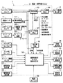
図1は、車両制御装置1のシステムブロック図である。車両制御装置1は認識・車間制御ECU3を中心に構成されている。認識・車間制御ECU3はマイクロコンピュータを主な構成として、入出力インターフェース(I/O)および各種の駆動回路や検出回路を備えている。これらのハード構成は一般的なものであるので詳細な説明は省略する。
FIG. 1 is a system block diagram of the
認識・車間制御ECU3は、レーザレーダセンサ5、車速センサ7、ブレーキスイッチ9、スロットル開度センサ11から各々検出信号を入力しており、警報音発生器13、距離表示器15、センサ異常表示器17、ブレーキ駆動器19、スロットル駆動器21および自動変速機制御器23に駆動信号を出力する。また認識・車間制御ECU3には、警報音量を設定する警報音量設定器24、警報判定処理における感度を設定する警報感度設定器25、クルーズコントロールスイッチ26、図示しないステアリングホイールの操作量を検出するステアリングセンサ27、及び自動車に発生したヨーレートを検出するヨーレートセンサ28が接続されている。また認識・車間制御ECU3は、電源スイッチ29を備え、電源スイッチ29がオンされることにより、所定の処理を開始する。
The recognition / vehicle distance control ECU 3 receives detection signals from the
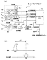
レーザレーダセンサ5は、認識・車間制御ECU3からの制御信号に基づいて駆動されるもので、図2に示すように、発光部、受光部及びレーザレーダCPU70などを主要部として構成されている。すなわち、レーザレーダセンサ5は、レーダユニットとしての発光部、受光部に加え、その発光・受光部における検出結果から、反射物体までの距離やその車幅方向及び車高方向における位置を演算するレーザレーダCPU70も備えている。
The
発光部は、パルス状のレーザ光を、発光レンズ71、スキャナ72及びガラス板77を介して放射する半導体レーザダイオード(以下、単にレーザダイオードと記載)75を備えている。レーザダイオード75は、レーザダイオード駆動回路76を介してレーザレーダCPU70に接続され、レーザレーダCPU70からの駆動信号によりレーザ光を放射(発光)する。また、スキャナ72には反射体としてのポリゴンミラー73が回転可能に設けられ、レーザレーダCPU70からの駆動信号がモータ駆動部74を介して入力されると、このポリゴンミラー73は図示しないモータの駆動力により回転する。なお、このモータの回転位置は、モータ回転位置センサ78によって検出され、レーザレーダCPU70に出力される。
The light emitting unit includes a semiconductor laser diode (hereinafter simply referred to as a laser diode) 75 that emits pulsed laser light through a light emitting lens 71, a
ポリゴンミラー73は、略六角錐台形状を成し、その6つの側面がミラーを構成している。そして、各側面の底面に対する面倒れ角が異なっていることから、ポリゴンミラー73は、車幅方向及び車高方向それぞれの所定角度の範囲で不連続にレーザ光を走査するように、レーザ光を出力することができる。本実施形態では、このポリゴンミラー73におけるミラーを構成する各側面は、面倒れ角の大きさに応じて順に1面、2面・・6面と面番号が付けられている。
The
レーザレーダセンサ5の受光部は、図示しない物体に反射されたレーザ光を受光レンズ81を介して受光し、その強度に対応する電圧を出力する受光素子(フォトダイオード)83とを備えている。そして、この受光素子83の出力電圧は、増幅器85にて増幅された後にコンパレータ87に出力される。コンパレータ87は増幅器85の出力電圧を基準電圧と比較し、出力電圧>基準電圧となったとき所定の受光信号を時間計測回路89へ出力する。
The light receiving unit of the
時間計測回路89には、レーザレーダCPU70からレーザダイオード駆動回路76へ出力される駆動信号も入力される。そして、図2(b)に示すように、上記駆動信号をスタートパルスPA、上記受光信号をストップパルスPBとし、2つのパルスPA,PB間の位相差(すなわちレーザ光を出射した時刻T0と反射光を受信した時刻T1との差ΔT)を2進デジタル信号に符号化する。また、ストップパルスPBのパルス幅も時間として計測する。
The
ここで、レーザ光の照射可能エリア及び、実際に先行車両等の物体を認識する時に使用される認識使用エリアについて、図3〜図9を用いて説明する。 Here, an area where laser light can be irradiated and a recognition use area used when actually recognizing an object such as a preceding vehicle will be described with reference to FIGS.
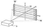
図3は、レーザレーダセンサの照射領域を示す斜視図を示している。出射されたレーザビームは、測定エリア121内の右端から左端にかけて例えば等間隔で出射されるが、図3では、測定エリア121内の右端および左端のパターン122のみが示してあり、その途中は省略してある。また、レーザ光パターン92は、図3では一例として楕円形のものを示しているが、この形に限られるものではなく長方形等でもよい。さらに、レーザ光を用いる他に、ミリ波等の電波や超音波等を用いるものであってもよい。また、スキャン方式にこだわる必要はなく、距離以外にX方向、Y方向における方位を測定できる方式であればよい。
FIG. 3 is a perspective view showing an irradiation area of the laser radar sensor. The emitted laser beams are emitted, for example, at equal intervals from the right end to the left end in the measurement area 121. In FIG. 3, only the pattern 122 at the right end and the left end in the measurement area 121 is shown, and the middle is omitted. It is. Further, the
図3に示すように、レーザレーダセンサ5は、レーザ光の照射方向をZ軸としたとき、これに垂直なXY平面内の照射可能エリア91内を順次走査することが可能である。
As shown in FIG. 3, the
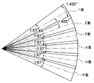
図4は、ポリゴンミラー73の各側面(1面〜6面)で反射されたレーザ光のY軸方向における広がり角、および、Y軸方向において隣接するレーザ光の重複範囲を示したものである。この図に示されるように、本実施形態では、車高方向(Y軸方向)に隣接するレーザ光が、その境界領域において一部重複するようにレーザ光の照射角度が設定されている。すなわち、Y軸方向において、各レーザ光は1.57degの広がり角を有している。その内、隣接するレーザ光が重複する角度範囲は、0.145degである。従って、各レーザ光の中心軸間の角度は1.425degとなる。
FIG. 4 shows the spread angle in the Y-axis direction of the laser light reflected by each side surface (1st to 6th surfaces) of the
このように、Y軸方向において隣接するレーザ光が一部重複するように照射角度を設定することにより、Y軸方向における分解能を向上することができる。つまり、図4の各レーザ光を上から下に向かってそれぞれ1面、2面、3面と定義した場合、1面のレーザ光のみを反射する場合、1面と2面のレーザ光を反射する場合、2面のレーザ光のみ反射する場合、2面と3面のレーザ光を反射する場合、及び3面のレーザ光のみ反射する場合の5つのパターンに識別できる。特に、2面のレーザ光においては、その両側に重複領域があるため、2面のレーザ光付近の分解能の向上度合いを高めることができる。 Thus, the resolution in the Y-axis direction can be improved by setting the irradiation angle so that adjacent laser beams partially overlap in the Y-axis direction. That is, when each laser beam in FIG. 4 is defined as one surface, two surfaces, and three surfaces from top to bottom, when only one surface laser beam is reflected, one surface and two surface laser beams are reflected. In this case, it is possible to discriminate between five patterns, that is, the case where only two laser beams are reflected, the case where two and three laser beams are reflected, and the case where only three laser beams are reflected. In particular, since the two-surface laser light has overlapping regions on both sides thereof, the degree of improvement in resolution near the two-surface laser light can be increased.
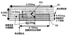
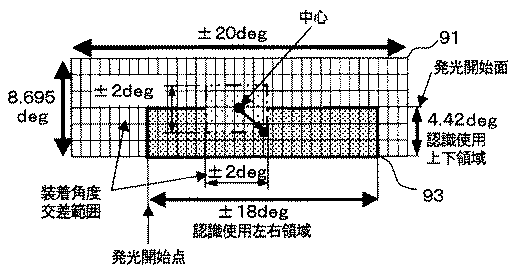
本実施形態の照射可能エリア91は、高さ方向であるY軸を基準方向、車幅方向であるX軸を走査方向とし、X軸方向には0.08deg×501点=±20degであり、Y軸方向には1.57deg×6ライン−0.145deg×5(重複領域)=8.695degである。また、スキャン方向はX軸方向については図3において左から右へ、Y軸方向については図3において上から下へである。
The irradiable
次に、図5〜図9に基づいて、認識使用エリア93について説明する。レーザレーダセンサ5は、車両の前面、例えば車両のバンパーの下部に装着される。このレーザレーダセンサ5から照射されるレーザ光は、自車両の前方に存在する物体、すなわち先行車両や走行車線を判定するためのデリニエータ(キャッツアイ)、ガードレール等に的確に向けられることが必要である。従って、レーザ光の照射エリアが上下左右にずれないように、レーザレーダセンサ5の装着角度を装着基準角度に合わせ込みながら車両に装着する必要がある。
Next, the recognition /
ここでの合わせ込みを、作業者が調整ボルト等のメカニカルな手段によってレーザレーダセンサ5の装着角度を調整するメカ調整によって行うことが可能であるが、メカ調整は、レーザレーダセンサ5の装着角度の装着基準角度に対する公差範囲が小さくなるほど困難な作業となり、またその作業時間も長くなってしまう。
The alignment here can be performed by a mechanical adjustment in which the operator adjusts the mounting angle of the
このため、本実施形態においては、メカ調整に加えて、レーザレーダセンサ5におけるソフト的な処理によるソフト調整を実行することで、レーザレーダセンサ5から照射されるレーザ光の角度範囲を、所望の基準角度範囲に合わせ込むようにしている。
For this reason, in this embodiment, in addition to the mechanical adjustment, by executing soft adjustment by software processing in the
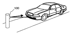
図6は、ソフト調整時の様子を示した模式図である。この図に示すように、レーザ光に対する反射率が高いターゲット100を所定高さの位置に設置しておき、このターゲット100から所定距離だけ離れた位置にレーザレーダセンサ5を装着した車両を移動させる。
FIG. 6 is a schematic diagram showing a state during soft adjustment. As shown in this figure, a
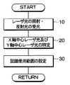
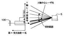
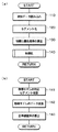
この状態において、車両制御装置を作動させ、レーザレーダCPU70にて、図7のフローチャートに示す処理を実行することにより、認識使用範囲93を設定する。すなわち、ステップ10では、ターゲット100に向けて発光部からレーザ光を照射させ、その反射光を受光部に受光させる。このときに照射するレーザ光の照射角度範囲は、図5に示すように、レーザレーダセンサ5の装着角度の公差範囲と一致したものとされる。なお、図5の例では、その公差範囲は、車幅方向及び車高方向にそれぞれ±2degであり、従来に比較して大幅に緩和されている。
In this state, the vehicle control device is operated, and the processing shown in the flowchart of FIG. That is, in
ここで、ターゲット100は、レーザレーダセンサ5の装着角度が装着基準角度に一致している場合、レーザ光の照射角度範囲の中心に位置するように設置される。従って、上記したレーザレーダセンサ5の装着角度の公差範囲に対応する照射角度範囲においてレーザ光を照射することにより、レーザレーダセンサ5はターゲット100からの反射光を必ず受光するができる。
Here, when the mounting angle of the
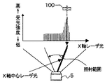
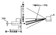
次に、ステップ20では、X軸及びY軸方向において、受光した反射波の中から最も受光強度の高い反射波に対応するレーザ光を中心レーザ光として特定する。この中心レーザ光の特定に関して、図8及び図9を用いて説明する。図8は、上述したレーザ光の照射角度範囲において、X軸方向にレーザ光を走査した場合における、各レーザ光に対するターゲット100による反射光の受光強度を示す。また、図9は、Y軸方向にレーザ光を走査した場合における、各レーザ光に対するターゲット100による反射光の受光強度を示す。図8及び図9から明らかなように、最も高い受光強度を示す反射光に対応するレーザ光をX軸中心レーザ光及びY軸中心レーザ光とするのである。
Next, in
なお、図8、図9の例は、図5に示されるように、ターゲット100の位置が、レーザレーダセンサ5の装着角度の公差範囲においてもっとも中心からずれた(X、Y軸方向にそれぞれ+2deg)場合を示している。従って、この場合には、それぞれレーザ光の照射角度範囲の端部において照射されるレーザ光がX軸及びY軸中心レーザ光となる。
In the example of FIGS. 8 and 9, as shown in FIG. 5, the position of the
そして、ステップ30において、X軸及びY軸中心レーザ光を基準として認識使用範囲93を設定する。すなわち、図5に示すように、そのX軸及びY軸中心レーザ光を中心として、X軸方向に±18deg(レーザ光451本に相当)の範囲を持った左右領域、Y軸方向に4.42deg(レーザ光3本に相当)の範囲を持った上下領域を定め、これを認識使用範囲93とする。そして、ポリゴンミラー73のうち認識使用範囲93に相当する面番号がレーザレーダCPU70内のメモリ等に記憶され、実際に先行車両等の物体を認識する時には、ポリゴンミラー73における認識使用範囲93に相当する面番号にレーザ光が照射されることで、スキャニングが行われる。
In
このようにしてターゲット100を用いて認識使用範囲93を設定することにより、認識使用範囲93の中心に位置する中心レーザ光を狙いとする基準角度に合わせ込むことができるので、結果として、その中心レーザ光を基準として設定される認識使用範囲93も、所望の認識領域に合致したものとなる。
By setting the
ただし、上述したように、X軸方向におけるレーザ光の分解能は0.08degと非常に高いが、それに比較してY軸方向におけるレーザ光の広がり角は1.57degであり、Y軸方向の分解能は低い。そのため、Y軸方向における中心レーザ光の照射角度をより高精度に認識するために上下光軸学習角度の算出処理を行なう。この上下光軸学習角度の算出処理について図10のフローチャート、図11及び図12の説明図に基づいて説明する。 However, as described above, the resolution of the laser beam in the X-axis direction is very high at 0.08 deg. However, the laser beam spread angle in the Y-axis direction is 1.57 deg. Is low. For this reason, in order to recognize the irradiation angle of the center laser beam in the Y-axis direction with higher accuracy, a calculation process of the upper and lower optical axis learning angles is performed. The calculation process of the up / down optical axis learning angle will be described with reference to the flowchart of FIG. 10 and the explanatory diagrams of FIGS.
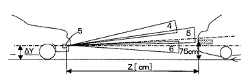
まず、図11に基づいて、レーザレーダセンサ5の装着高さΔYと、Y軸中心レーザ光の目標とする基準角度ΔAの関係について説明する。レーザレーダセンサ5は車両のバンパー下部等に装着されるものであるが、その装着高さΔYは、車種ごとに変化する。このとき、装着高さΔYが小さい、すなわち地上から低い位置にレーザレーダセンサ5が装着される場合には、Y軸中心レーザ光の中心角度が上向きに設定されることが好ましい。一方、その装着高さΔYが大きい場合には、Y軸中心レーザ光の中心角度がほぼ水平に設定されることが好ましい。
First, the relationship between the mounting height ΔY of the
このように、レーザレーダセンサ5の装着高さΔYに応じて、Y軸中心レーザ光の中心角度の狙いとする基準角度は異なる。そのため、本実施形態では、この基準角度をΔAとし、車種ごとに設定する。例えば、装着高さΔYが小さい車種に対しては、基準角度ΔAを0.5degに設定し、装着高さΔYが大きい車種に対しては、基準角度ΔAを0degに設定する。そして、以下に説明する上下光軸学習角度Δθelvは、Y軸中心レーザ光の中心角度が基準角度ΔAに対してどの程度ずれているかを示すずれ角として算出されるものである。
Thus, the target reference angle for the center angle of the Y-axis center laser beam varies depending on the mounting height ΔY of the
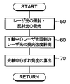
図10のステップ50において、認識使用範囲93が設定された後に、その認識使用範囲93のターゲット100が存在する中心付近において、Y軸中心レーザ光及びその両側のレーザ光を照射するとともに、その反射光を受光する。例えば図12に示す例では、Y軸中心レーザ光は面番号が5のレーザ光であり、その両側において照射されるレーザ光は、面番号が4及び6のレーザ光となる。
In
そして、ステップ60において、Y軸中心レーザ光の両側のレーザ光による反射光の受光強度を計測する。この受光強度の計測においては、複数のレーザ光の受光強度を平均化した平均化受光強度を用いても良いし、1つのレーザ光の受光強度をそのまま用いても良い。
In
ステップ70では、計測した受光強度に基づいて、Y軸中心レーザ光の中心角度の基準角度ΔAに対するずれ角度Δθelvを算出する。すなわち、図12に示す例においては、面番号4及び6のレーザ光による反射光の受光強度に基づいて、Y軸中心レーザ光である面番号5のレーザ光内において、その中心角度が基準角度ΔAに対して、どの程度ずれているかを示すずれ角Δθelvを算出する。具体的な算出方法としては、例えば、面番号4の受光強度:面番号6の受光強度=3:1である場合には、(広がり角1.57deg−重複範囲0.145×2)×3/(3+1)−0.64deg=0.32degとして、面番号4のレーザ光側に0.32degだけずれていると算出することができる。
In
この算出式で示される0.64degとは、広がり角1.57degから重複範囲0.145×2を減算したものを1/2倍したものであり、面番号4および6の受光強度の比から想定される基準角度ΔAから面番号5のレーザ光の中心角度を差し引くことで、そのずれ角Δθelvが求められる。
The 0.64 deg shown in this calculation formula is a value obtained by subtracting the overlapping range 0.145 × 2 from the spread angle 1.57 deg. By subtracting the center angle of the laser beam with the
このとき、基準角度ΔAに対応する角度が面番号5のレーザ光の中心角度に対して面番号4のレーザ光側に位置している場合、レーザレーダセンサ5の光軸の向きが全体として下向きとなっていることになる。このため、この場合には、ずれ角Δθelvは、マイナス(−)の符号を付けて表される。一方、面番号6のレーザ光側にずれている場合には、レーザレーダセンサ5の光軸の向きが上向きとなっていることになる。このため、この場合には、ずれ角Δθelvは、プラス(+)の符号を付けて表される。
At this time, when the angle corresponding to the reference angle ΔA is located on the laser beam side of the
なお、基準角度ΔAに対するずれ角Δθelvの算出方法については、上述した手法に限られるものではない。例えば、面番号4及び6の受光強度の差を求め、その差に応じてずれ角Δθelvを求めても良い。さらに、面番号5のY軸中心レーザ光の受光強度を基準として、面番号4及び6のレーザ光の受光強度に応じた角度をそれぞれ求め、それらの角度を減算することにより、ずれ角Δθelvを求めても良い。
Note that the method of calculating the deviation angle Δθelv with respect to the reference angle ΔA is not limited to the method described above. For example, the difference between the received light intensities of the
本来であれば、面番号5のレーザ光のY軸方向における広がり角度の中心角度が基準角度ΔAに一致するようにターゲット100を設置することが理想である。しかしY軸方向のレーザ光の広がり角が大きいため、その広がり角内でターゲット100の位置が変化しても、それを検知することができない。そこで、上述したように、Y軸中心レーザ光の両側において照射されるレーザ光の受光強度を用いることにより、より詳細なレーザ光の上下光軸中心を算出できるのである。このY軸中心レーザ光の広がり角の中心角度が、基準角度ΔAからずれている場合に、そのずれ角度Δθelvを上下光軸学習角度として記憶する。
Originally, it is ideal to install the
このようにして上下光軸学習角度Δθelvを求めることで、後述するように、先行車両等の物体の認識をより高精度に行なうことが可能になる。 By obtaining the vertical optical axis learning angle Δθelv in this manner, it becomes possible to recognize an object such as a preceding vehicle with higher accuracy, as will be described later.
レーザレーダセンサ5が、上述した手順で、認識使用範囲93を設定した後、実際に自車両の前方に存在する物体を認識する際には、レーザレーダCPU70が認識使用範囲93内を2次元的にレーザ光をスキャンさせる。このような2次元的なスキャンにより、走査方向を示すスキャン角度θx,θyと測距された距離rとが得られる。なお、2つのスキャン角度θx,θyは、それぞれ出射されたレーザビームとYZ平面に投影した線とZ軸との角度を縦スキャン角θy、出射されたレーザビームをXZ平面に投影した線とZ軸との角度を横スキャン角θxと定義する。
When the
レーザレーダCPU70は、時間計測回路89から入力された2つのパルスPA,PB間の時間差ΔTから物体までの距離を算出し、その距離及び対応するスキャン角度θx,θyを基にして位置データを作成する。つまり、レーザレーダ中心を原点(0,0,0)とし、車幅方向をX軸、車高方向をY軸、車両前方方向をZ軸とするXYZ直交座標に変換する。そして、このXYZ直交座標に変換された(X,Y,Z)データ及び受光信号強度データ(ストップパルスPBのパルス幅が相当する)を測距データとして認識・車間制御ECU3へ出力する。
The
認識・車間制御ECU3は、レーザレーダセンサ5からの測距データを基にして物体を認識し、その認識物体から得た先行車の状況に合わせて、ブレーキ駆動器19、スロットル駆動器21および自動変速機制御器23に駆動信号を出力することにより車速を制御する、いわゆる車間制御を実施する。また、認識物体が所定の警報領域に所定時間存在した場合等に警報する警報判定処理も同時に実施する。この場合の物体としては、自車の前方を走行する前車やまたは停止している前車等が該当する。
The recognition / vehicle distance control ECU 3 recognizes an object based on the distance measurement data from the
続いて認識・車間制御ECU3の内部構成について制御ブロックとして説明する。レーザレーダセンサ5から出力された測距データは物体認識ブロック43に送られる。物体認識ブロック43では、測距データとして得た3次元位置データに基づいて、物体の中心位置(X,Y,Z)、及び幅、奥行き、高さ等の大きさ(W,D,H)を求める。さらに、中心位置(X,Y,Z)の時間的変化に基づいて、自車位置を基準とするその物体の相対速度(Vx,Vy,Vz)を求める。さらに物体認識ブロック43では、車速センサ7の検出値に基づいて車速演算ブロック47から出力される車速(自車速)と上記求められた相対速度(Vx,Vy,Vz)とから物体が停止物体であるか移動物体であるかの識別が行なわれる。この識別結果と物体の中心位置とに基づいて自車両の走行に影響する物体が選択され、その距離が距離表示器15により表示される。
Next, the internal configuration of the recognition / vehicle distance control ECU 3 will be described as a control block. The distance measurement data output from the
また、ステアリングセンサ27からの信号に基づいて操舵角演算ブロック49にて操舵角が求められ、ヨーレートセンサ28からの信号に基づいてヨーレート演算ブロック51にてヨーレートが演算される。そしてカーブ半径(曲率半径)算出ブロック57では、車速演算ブロック47からの車速と操舵角演算ブロック49からの操舵角とヨーレート演算ブロック51からのヨーレートとに基づいて、カーブ半径(曲率半径)Rを算出する。そして物体認識ブロック43では、このカーブ半径Rおよび中心位置座標(X,Z)などに基づいて車両形状確率や自車線確率を算出する。この車両形状確率や自車線確率については後述する。
Further, the steering angle is calculated by the steering
このようなデータを持つ物体のモデルを「物標モデル」と呼ぶこととする。この物体認識ブロック43にて求めたデータが異常な範囲の値がどうかがセンサ異常検出ブロック44にて検出され、異常な範囲の値である場合には、センサ異常表示器17にその旨の表示がなされる。
An object model having such data is called a “target model”. The sensor
一方、先行車判定ブロック53では、物体認識ブロック43から得た各種データに基づいて先行車両を選択し、その先行車両に対する距離Zおよび相対速度Vzを求める。そして、車間制御部及び警報判定部ブロック55が、この先行車両との距離Z、相対速度Vz、クルーズコントロールスイッチ26の設定状態およびブレーキスイッチ9の踏み込み状態、スロットル開度センサ11からの開度および警報感度設定器25による感度設定値に基づいて、警報判定ならば警報するか否かを判定し、クルーズ判定ならば車速制御の内容を決定する。その結果を、警報が必要ならば、警報発生信号を警報音発生器13に出力する。また、クルーズ判定ならば、自動変速機制御器23、ブレーキ駆動器19およびスロットル駆動器21に制御信号を出力して、必要な制御を実施する。そして、これらの制御実行時には、距離表示器15に対して必要な表示信号を出力して、状況をドライバーに告知する。
On the other hand, in the preceding
このような車間制御や警報判定に際しては、その前提となる物体認識、さらに詳しく言えば、ここでの認識対象物体である車両の認識が適切に行われていることが重要である。そこで、その車両認識を適切に行なうため、認識・車間制御ECU3の物体認識ブロック43において実行される物体認識に関する処理について説明する。
In such inter-vehicle distance control and warning determination, it is important that object recognition as a premise thereof, more specifically, recognition of a vehicle that is a recognition target object here is appropriately performed. Therefore, in order to appropriately perform the vehicle recognition, processing related to object recognition executed in the
図13(a)のフローチャートに物体認識に係るメイン処理を示す。図13(a)のステップ110では、レーザレーダセンサ5から1スキャン分の測距データの読み込みを行なう。レーザレーダセンサ5でのスキャン周期は例えば100msecであり、100msec毎にデータを取り込む。
The main process related to object recognition is shown in the flowchart of FIG. In
ステップ120では、データのセグメント化を行なう。上述したように、測距データとして得た3次元位置データをグルーピングしてセグメントを形成する。このセグメント化においては、所定の接続条件(一体化条件)に合致するデータ同士を集めて1つのプリセグメントデータを生成し、さらにそのプリセグメントデータ同士の内で所定の接続条件(一体化条件)に合致するものを集めて1つの本セグメントデータとするというものである。プリセグメントデータは、例えば点認識されたデータ同士のX軸方向の距離△Xが0.2m以下、Z軸方向の距離△Zが2m以下という2条件を共に満たす場合に、その点集合を一体化して求める。本実施形態では、Y軸方向に3つの走査ラインがあるが、プリセグメント化によって各ライン毎にプリセグメントデータが生成されている。そのため、本セグメント化では、3次元(X,Y,Z)空間で近接するプリセグメントデータ同士を一体化(本セグメント化)する。本セグメントデータは、X軸,Y軸及びZ軸にそれぞれ平行な3辺を持つ直方体の領域であり、その中心座標(X,Y,Z)と大きさを示すための3辺の長さ(W,H,D)をデータ内容とする。なお、特に断らない限り、本セグメント(データ)のことを単にセグメント(データ)と称することとする。
In
ステップ130では、各セグメントデータをプリ物標とし、各プリ物標について、物標モデルとして物標化処理の対象となる確率である物標化優先確率を計算する。ここで、物標モデルとは、一まとまりのセグメントに対して作成される物体のモデルであり、プリ物標とは、物標化処理を行なう物標モデルの候補となるものである。本実施形態においては、プリ物標は最大で18個選択可能であり、物標モデルは、それらプリ物標の中から物標化優先確立の高い順に4個選択される。
In
各プリ物標の物標化優先確率は、車両形状確率が所定確率(例えば50%)以上か否か、移動物か否か、自車両に対する横方向位置が所定距離(例えば左右それぞれに6m)以内であるか否か、所定時間以上継続して検出されているか否か等を判定要素として、該当する項目が多いほど確率が高くなるように算出される。 The target targeting priority probability of each pre-target is whether the vehicle shape probability is a predetermined probability (for example, 50%) or more, whether it is a moving object, and the lateral position with respect to the host vehicle is a predetermined distance (for example, 6 m for each of left and right) It is calculated so that the probability increases as the number of applicable items increases, with the determination factors such as whether or not it is within a predetermined time and whether or not the detection is continued for a predetermined time or more.
ここで、車両形状確率について説明する。 Here, the vehicle shape probability will be described.
路側にデリニエータが狭い間隔で多数設置されているような場合やガードレールを検出しているような場合には、これらの停止物を移動物であると誤認識してしまう可能性がある。これは、同一位置に常に何かを検出することにより、その位置に自車と同速度で走行している車両が存在すると判定してしまうからである。そこで、このように移動物であると誤認識した物体が誤って先行車と判定されてしまわないように、車両形状確率を算出する。そして、先行車判定ブロック53においてこの車両形状確率が例えば50%未満の場合に路側物であると判定するようにすれば、繰り返し現れる停止物を誤って先行車両と判定することを防止できる。
When many delineators are installed on the road side at a narrow interval or when a guardrail is detected, there is a possibility that these stopped objects are erroneously recognized as moving objects. This is because by always detecting something at the same position, it is determined that there is a vehicle traveling at the same speed as the host vehicle at that position. Therefore, the vehicle shape probability is calculated so that an object that is erroneously recognized as a moving object is not erroneously determined as a preceding vehicle. If it is determined in the preceding
車両形状確率の取り得る範囲は0〜100%であり、瞬間的なノイズやバラツキによる影響を低減するために、数式1のように加重平均して求める。
The range that the vehicle shape probability can take is 0 to 100%. In order to reduce the influence of instantaneous noise and variations, the vehicle shape probability is obtained by weighted averaging as in
(数1)
今回の車両形状確率←前回値×α+今回の瞬時値×(1−α)
なお、初期値は50%とし、αは例えば0.8といった値を採用する。また、車両形状確率の瞬時値は、相対加速度、縦横の長さD,W、検出時間などに基づいて算出する。なお、この車両形状確率の算出方法は、特開2002−40139の段落番号0045から0049に詳しく記載されているため、これ以上の説明は省略する。
(Equation 1)
Current vehicle shape probability ← previous value × α + current instantaneous value × (1-α)
The initial value is 50%, and α is a value such as 0.8. Further, the instantaneous value of the vehicle shape probability is calculated based on relative acceleration, vertical and horizontal lengths D and W, detection time, and the like. Note that this vehicle shape probability calculation method is described in detail in paragraphs 0045 to 0049 of JP-A-2002-40139, and thus further description thereof is omitted.
ステップ140では、物標化優先確率の高い4つのプリ物標を物標として選択し、それらに対して物標化処理を行なう。この物標化処理を図13(b)のフローチャートを参照して説明する。物標化処理においてはまず、物標モデルの対応セグメントを検索する(ステップ141)。これは、前回までに得た物標モデルが、今回検出したセグメントの内のいずれと一致するかを検索する処理であり、物標モデルに対応するセグメントとは次のように定義する。まず、物標モデルが前回処理時の位置から前回処理時における相対速度で移動したと仮定した場合、現在物標モデルが存在するであろう推定位置を算出する。続いて、その推定位置の周囲に、X軸,Y軸,Z軸方向それぞれに所定量の幅を有する推定移動範囲を設定する。そして、その推定移動範囲に少なくとも一部が含まれるセグメントを対応セグメントとする。
In
ステップ142では、物標モデルのデータ更新処理を実行する。この処理は、対応するセグメントがあれば物標モデルの過去データを現在のデータに基づいて更新するもので、更新されるデータは、中心座標(X,Y,Z)、幅W、高さH、奥行きD、X軸方向,Y軸方向、Z軸方向の相対速度(Vx,Vy,Vz)、中心座標(X,Y,Z)の過去4回分のデータ、自車線確率などである。なお、対応するセグメントがない場合は、物標モデルのデータ更新は行なわず、新規物標モデルの登録を行なう。
In
その後、ステップ143にて、自車線確率の算出を行なう。自車線確率とは、物標モデルが自車と同一レーンを走行している車両である確からしさを表すパラメータである。具体的には、まず物標モデルの位置を算出し、その算出した位置を自車線確率マップに重ねて、物標モデルの自車線確率瞬時値を求める。なお、自車線確率マップとは、自車の前方の所定の範囲(例えば左右それぞれ5m、前方100m)を複数の領域に分け、距離が近いほど、また、自車の進路上に近いほど、確率が高くなるように各領域に確率が付与されているマップである。
Thereafter, in
自車線確率瞬時値を求めた後は、数式2のように加重平均して自車線確率を求める。
After the instantaneous value of the own lane probability is obtained, the own lane probability is obtained by weighted averaging as shown in
(数2)
自車線確率←自車線確率前回値×α+自車線確率瞬時値×(1−α)
ここで、αは一定値でも良いし、物標モデルとの距離や物標モデルが存在する領域に応じて変化するものであっても良い。なお、自車線確率の算出方法についても、特開2002−40139の段落番号0050から0056に詳しく記載されているため、これ以上の詳細な説明は省略する。
(Equation 2)
Own lane probability ← Own lane probability previous value × α + Own lane probability instantaneous value × (1-α)
Here, α may be a constant value, or may vary according to the distance from the target model and the region where the target model exists. Note that the calculation method of the own lane probability is also described in detail in paragraphs 0050 to 0056 of JP-A-2002-40139, and thus detailed description thereof is omitted.
そして、車両形状確率や自車線確率も含めた物標モデルのデータが、図1に示す物体認識ブロック43から先行車判定ブロック53へ出力される。なお、先行車判定ブロック53では、例えば車両形状確率が所定のしきい値(例えば50%)以上、且つ自車線確率が所定のしきい値(例えば50%)以上の物標モデルの中で、距離Zが最小のものを先行車と判定する。この判定結果は車間制御部及び警報判定部ブロック55に出力されることとなる。
Then, the target model data including the vehicle shape probability and the own lane probability is output from the
次に、レーザレーダセンサ5の光軸中心の学習処理について説明する。
Next, the optical axis center learning process of the
ターゲット100を用いてレーザレーダセンサ5における認識使用エリア93の中心レーザ光の照射角度を基準角度ΔAに一致するように設定した場合であっても、実際のレーザ光の照射範囲は、種々の要因で変動する。例えば、車両の積載状態や搭乗人員等によって、特にY軸(上下)方向において、レーザレーダセンサ5のレーザ光照射範囲は、認識使用エリア93として設定した範囲からずれる場合がある。また、車両が走行を繰り返すことにより、走行振動等の影響を受けてレーザレーダセンサ5の車両装着状態が変化することもありえる。このように、特にY軸方向におけるレーザ光の照射角度が変動し易いため、上述したように所定のターゲット100に基づいて算出した上下光軸学習角度Δθelvがずれているかどうかを判別して、ずれている場合には、補正を行なうことが好ましいのである。
Even when the irradiation angle of the central laser beam in the
本実施形態においては、乗用車に必ず装着されているリフレクタを用いて、レーザレーダセンサ5の光軸中心の学習を行なう。その理由は、乗用車のリフレクタは地上から約75cmの位置に設置され、車種ごとの取り付け高さのばらつき範囲も小さいためである。
In the present embodiment, the center of the optical axis of the
図14にレーザレーダセンサ5の光軸中心の学習処理のフローチャートを示す。まず、ステップ200において、複数のプリ物標に対する物標化優先確率を算出する。この物標化優先確立の算出方法は、既に図13(a)のフローチャートのステップ130にて説明した方法と基本的に同様である。
FIG. 14 shows a flowchart of the learning process of the optical axis center of the
ただし、本学習処理では、上述した上下光軸学習角度Δθelvを用いて、より詳細に車両と車両以外のプリ物標を識別し、車両以外のプリ物標に関しての物標化優先確率を、所定の低い確率(例えば20%)に制限する。以下、上下光軸学習角度Δθelvを用いた車両と車両以外のプリ物標の識別方法について説明する。なお、この識別方法は、図13(a)のフローチャートのステップ130において適用し、車両以外のプリ物標の物標化優先確率を所定の低い確率に制限しても良い。
However, in this learning process, the above-described vertical optical axis learning angle Δθelv is used to identify the vehicle and the pre-target other than the vehicle in more detail, and the target priority priority for the pre-target other than the vehicle is set to a predetermined value. Is limited to a low probability (for example, 20%). Hereinafter, a method for identifying a vehicle and a pre-target other than the vehicle using the vertical optical axis learning angle Δθelv will be described. This identification method may be applied in
まず、上下光軸学習角度Δθelvと上向き判定角度(例えば+0.5deg)及び下向き判定角度(例えば−0.5deg)と比較することにより、光軸の上向きもしくは下向き判定を行なう。すなわち、上下光軸学習角度Δθelv≧+0.5degであれば上向き判定がなされ、上下光軸学習角度Δθelv≦−0.5degであれば下向き判定がなされる。 First, the upward or downward optical axis learning angle Δθelv is compared with an upward determination angle (for example, +0.5 deg) and a downward determination angle (for example, −0.5 deg), thereby determining whether the optical axis is upward or downward. That is, an upward determination is made if the vertical optical axis learning angle Δθelv ≧ + 0.5 deg, and a downward determination is made if the vertical optical axis learning angle Δθelv ≦ −0.5 deg.
そして、光軸上向き判定がなされている場合には、以下の条件(1)もしくは(2)が成立するプリ物標に関する物標化優先確率を所定の低い確率に制限する。なお、各条件の説明に際して、適宜図11に示す例を参照する。 If the optical axis upward determination is made, the target priority probability for the pre-target that satisfies the following condition (1) or (2) is limited to a predetermined low probability. In the description of each condition, an example shown in FIG. 11 will be referred to as appropriate.
(1)Y軸中心レーザ光の下側のレーザ光のみによって反射光が受光され、かつプリ物標との距離Z(cm)>装着高さΔY(cm)×40+D(cm)が成立した場合
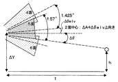
図11に示すように、本実施形態においては、Y軸方向のレーザ光の広がり角は1.57degであり、tan(1.57deg)≒1/37となる。また、中心レーザ光下側のレーザ光のみの広がり角度、すなわち重複領域を除くレーザ光の広がり角度は、1.57−0.145=1.425degであり、tan(1.425deg)≒1/40となる。
(1) When the reflected light is received only by the laser beam below the Y-axis center laser beam and the distance Z (cm) from the pre-target> mounting height ΔY (cm) × 40 + D (cm) is satisfied As shown in FIG. 11, in the present embodiment, the spread angle of the laser light in the Y-axis direction is 1.57 deg, and tan (1.57 deg) ≈1 / 37. Further, the spread angle of only the laser beam below the center laser beam, that is, the spread angle of the laser beam excluding the overlapping region is 1.57−0.145 = 1.425 deg, and tan (1.425 deg) ≈1 / 40.
ここで、Y軸中心レーザ光の下側のレーザ光(6面のレーザ光)は、原則として水平よりも下向きに照射される。しかし、光軸上向き判定がなされたときには、6面のレーザ光の上端がほぼ水平となる場合もある。そのような場合であっても、プリ物標との距離Zが上記の式を満足する場合には、6面のレーザ光の下端は少なくとも路面に達している。また、6面のレーザ光に対して反射光が生じ、Y軸中心レーザ光である5面のレーザ光によって反射光が生じていないのであるから、その反射光を生じているプリ物標は路面上もしくは路面に非常に近い位置にあると推測できる。このため、このプリ物標は、例えばデリニエータ等の車両以外の物体と推測できる。 Here, in principle, the lower laser beam (six-surface laser beam) of the Y-axis center laser beam is irradiated downward from the horizontal. However, when the upward determination of the optical axis is made, the upper end of the six-surface laser light may be substantially horizontal. Even in such a case, if the distance Z to the pre-target satisfies the above formula, the lower end of the six laser beams reaches at least the road surface. Further, since reflected light is generated with respect to the six-surface laser light and no reflected light is generated by the five-surface laser light that is the Y-axis center laser light, the pre-target generating the reflected light is the road surface. It can be inferred that it is on or very close to the road surface. For this reason, this pre target can be estimated as an object other than a vehicle such as a delineator.
なお、上記した式におけるD(cm)は、測距誤差と道路の勾配等を考慮して設定した余裕値であり、例えば500(cm)に設定される。 Note that D (cm) in the above equation is a margin value set in consideration of distance measurement error, road gradient, and the like, and is set to 500 (cm), for example.
(2)Y軸中心レーザ光の上側のレーザ光、もしくはY軸中心レーザ光とその上側のレーザ光の両方に対して反射光が受光され、かつプリ物標との距離Z(cm)>(350(cm)−ΔY(cm))×37+D(cm)が成立した場合
光軸上向き判定がなされている場合には、上述したように、Y軸中心レーザ光の下端がほぼ水平に近くなる場合がある。従って、図11に示す例では、Y軸中心レーザ光である5面のレーザ光及びその上側に照射される4面のレーザ光の照射方向は、上方に広がるようになる。ここで、道路上方には標識や看板等の物体が多数設置されており、上方に広がる4面及び5面のレーザ光によって、それらの物体による反射光を受光しやすくなる。上記の(2)の条件は、そのような道路上方の物体からの反射光を受光する可能性がある場合に成立するものである。
(2) Reflected light is received with respect to the upper laser beam of the Y-axis center laser beam, or both the Y-axis center laser beam and the upper laser beam, and the distance Z (cm)> ( When 350 (cm) −ΔY (cm)) × 37 + D (cm) is established When the optical axis upward determination is made, as described above, when the lower end of the Y-axis center laser beam is nearly horizontal There is. Accordingly, in the example shown in FIG. 11, the irradiation directions of the five laser beams that are the Y-axis center laser beam and the four laser beams that are irradiated on the five laser beams spread upward. Here, a large number of objects such as signs and signboards are installed above the road, and the reflected light from these objects can be easily received by the laser beams of the four and five surfaces spreading upward. The above condition (2) is established when there is a possibility of receiving reflected light from an object above the road.
すなわち、例えばトラック等の車高の高い車両であっても、その車高の最大値は350(cm)程度である。そのため、4面及び5面のレーザ光による反射があり、その反射光を生じたプリ物標までの距離Zが、5面のレーザ光(Y軸中心レーザ光)の照射高さがその350(cm)を超える距離よりも長い場合、車両以外の物体からの反射光である可能性が高い。従って、そのような場合には、プリ物標の物標化優先確率を制限するのである。なお、4面のレーザ光のみによって反射光が生じている場合も同様である。 That is, even if the vehicle height is high, such as a truck, the maximum value of the vehicle height is about 350 (cm). Therefore, there is reflection by the laser light on the 4th surface and the 5th surface, and the distance Z to the pre-target that generated the reflected light is 350 (the laser light (Y-axis center laser light) irradiation height is 350 ( When the distance is longer than a distance exceeding cm), there is a high possibility that the reflected light is from an object other than the vehicle. Therefore, in such a case, the target priority probability of the pre-target is limited. The same applies to the case where the reflected light is generated only by the four laser beams.
次に、光軸下向き判定がなされている場合について説明する。光軸下向き判定がなされている場合は、以下の条件(3)もしくは(4)が成立すると、プリ物標に関する物標化優先確率を所定の低い確率に制限する。 Next, a case where the optical axis downward determination is made will be described. When the optical axis downward determination is made, if the following condition (3) or (4) is satisfied, the target priority priority for the pre-target is limited to a predetermined low probability.
(3)Y軸中心レーザ光の下側のレーザ光、もしくはY軸中心レーザ光とその下側のレーザ光の両方によって反射光が受光され、かつプリ物標との距離Z(cm)>ΔY(cm)×37+D(cm)が成立した場合
光軸下向き判定がなされている場合には、光軸上向き判定の場合とは逆に、Y軸中心レーザ光の上端が水平に近づく場合がある。従って、図11に示す例では、Y軸中心レーザ光である5面のレーザ光及びその下側に照射される6面のレーザ光の照射方向は、下方に広がり、路面や路面上の低い位置にある物体からの反射光を受光しやすくなる。上記の(3)の条件は、そのような路面や路面上の低い位置にある物体からの反射光を受光する可能性がある場合に成立するものである。
(3) The reflected light is received by the lower laser beam of the Y-axis center laser beam, or both the Y-axis center laser beam and the lower laser beam, and the distance Z (cm)> ΔY from the pre-target When (cm) × 37 + D (cm) is satisfied When the optical axis downward determination is made, the upper end of the Y-axis center laser light may approach horizontal, contrary to the case of optical axis upward determination. Therefore, in the example shown in FIG. 11, the irradiation directions of the five laser beams that are the Y-axis center laser beam and the six laser beams irradiated below the Y-axis center laser beam spread downward, and are low positions on the road surface and road surface. It becomes easy to receive the reflected light from the object in. The above condition (3) is established when there is a possibility of receiving reflected light from such a road surface or an object at a low position on the road surface.
すなわち、上述したように、レーザ光の広がり角度が1.57degであるため、そのtan(1.57deg)の値にレーザレーダセンサ5の装着高さΔYを乗算することによって、Y軸中心レーザ光である5面のレーザ光がほぼ路面に達する距離が算出される。その距離に余裕値D(cm)を加えた距離よりも、プリ物標までの距離Zが長く、かつ5面及び6面のレーザ光の両方、もしくは6面のレーザ光のみに対して反射光を受光している場合には、路面上の非常に低い位置からの反射であると推測できる。従って、そのような場合には、プリ物標の物標化優先確率を制限する。
That is, as described above, since the spread angle of the laser light is 1.57 deg, by multiplying the value of tan (1.57 deg) by the mounting height ΔY of the
(4)Y軸中心レーザ光の上側のレーザ光のみによって反射光が受光され、かつプリ物標との距離Z(cm)>(350(cm)―ΔY(cm))×40+D(cm)が成立した場合
光軸下向き判定がなされた場合、Y軸中心レーザ光の上側のレーザ光(4面のレーザ光)は、水平よりも上方ではあるが、相対的に水平方向に近い向きに照射される。このような場合であっても、プリ物標との距離Zが上記の式を満足する場合には、4面のレーザ光の上端は少なくとも最も高い車高以上の高さに達している。また、4面のレーザ光に対して反射光が生じ、Y軸中心レーザ光である5面のレーザ光によって反射光が生じていないのであるから、その反射光を生じているプリ物標は路面上の非常に高い位置にあると推測できる。このため、(4)の条件が成立した場合には、プリ物標が、標識や看板等の車両以外の物体である可能性があると推測できるのである。
(4) The reflected light is received only by the upper laser beam of the Y-axis center laser beam, and the distance from the pre-target Z (cm)> (350 (cm) −ΔY (cm)) × 40 + D (cm) When it is established When the optical axis downward determination is made, the laser light on the upper side of the Y-axis center laser light (four-surface laser light) is irradiated in a direction relatively close to the horizontal direction, although it is above the horizontal. The Even in such a case, when the distance Z to the pre-target satisfies the above expression, the upper ends of the four laser beams have reached at least a height higher than the highest vehicle height. In addition, reflected light is generated with respect to the four-surface laser light, and no reflected light is generated with the five-surface laser light that is the Y-axis center laser light. Therefore, the pre-target that generates the reflected light is the road surface. It can be inferred that it is in a very high position above. For this reason, when the condition of (4) is satisfied, it can be estimated that the pre-target may be an object other than a vehicle such as a sign or a signboard.
また、上述した(1)〜(4)の条件に加えて、次のような条件が成立した場合にも、プリ物標の物標化優先確率を制限しても良い。 Further, in addition to the above conditions (1) to (4), the target priority probability of the pre-target may be limited even when the following condition is satisfied.
(5)図11に示されるように、水平方向と5面のレーザ光の下端とのなす角度Δθが、所定角度Θ以上であり、プリ物標との距離が所定の近距離l(例えば30m)以内であり、プリ物標の幅が車両の幅よりも短く(例えば0.5m以下)、6面のレーザ光のみによって反射光を受光している場合
上記所定角度Θの設定方法について説明する。まず、Y軸中心レーザ光である5面のレーザ光下端の、所定の近距離lにおける基準照射高さhを定める(例えば地上から30cm)。この基準照射高さhに基づき、数式3によって所定角度Θを演算する。
(5) As shown in FIG. 11, the angle Δθ formed by the horizontal direction and the lower ends of the five laser beams is equal to or greater than a predetermined angle Θ, and the distance from the pre-target is a predetermined short distance l (for example, 30 m). ), The width of the pre-target is shorter than the width of the vehicle (for example, 0.5 m or less), and the reflected light is received only by the six-surface laser light. . First, a reference irradiation height h at a predetermined short distance l at the lower end of the five laser beams that are Y-axis center laser beams is determined (for example, 30 cm from the ground). Based on this reference irradiation height h, a predetermined angle Θ is calculated by Equation 3.
(数3)
Θ=tan−1(ΔY−h)/l
水平方向と5面のレーザ光の下端とのなす角度Δθが、このように設定した所定角度Θ以上である場合、上述したように基準照射高さhは、比較的低い位置に設定されるので、5面のレーザ光の照射範囲が少なくとも距離l以上においては地上高30cmの対象物をカバーすることになる。換言すれば、距離l以内において、6面のレーザ光のみに対して反射光が生じている場合、その反射物の高さは、せいぜい基準照射高さh程度の高さしか持たないことになる。
(Equation 3)
Θ = tan−1 (ΔY−h) / l
When the angle Δθ formed by the horizontal direction and the lower end of the laser light on the five surfaces is not less than the predetermined angle Θ set in this way, the reference irradiation height h is set at a relatively low position as described above. When the irradiation range of the five laser beams is at least the distance l or more, the object having a ground height of 30 cm is covered. In other words, within the distance l, when reflected light is generated with respect to only the six-surface laser light, the height of the reflecting object is at most as high as the reference irradiation height h. .
従って、反射物が車両であり、所定の近距離以内に接近した場合には、上述した基準照射高さh程度の高さしか持たないことはなく、5面のビーム光によっても反射光を受光するはずである。 Therefore, when the reflecting object is a vehicle and approaches within a predetermined short distance, it does not have the height of the reference irradiation height h described above, and the reflected light is received also by the five-surface beam light. Should do.
従って、上記の条件が成立した場合には、その反射物(プリ物標)は、車両以外の例えばデリニエータ等と推測できるので、物標化優先確率を所定の低い確率に制限する。 Therefore, when the above condition is satisfied, the reflected object (pre-target) can be assumed to be a delineator other than the vehicle, for example, so that the target priority probability is limited to a predetermined low probability.
なお、上記の条件(5)においては、プリ物標の幅が所定の幅以下であることも、条件の成立要件の1つとしているが、これは確認的な意味であり、この成立要件は省略しても良い。 In the above condition (5), the pre-target width being equal to or smaller than the predetermined width is also one of the requirements for establishing the condition. May be omitted.
このようにして、各プリ物標に対して物標化優先確率を算出した後は、図14のフローチャートのステップ210において、学習対象候補の第1抽出を行なう。この第1抽出では、移動物として認識しており、その認識が所定時間(例えば5秒)以上継続し、前述した車両形状確率が50%以上のプリ物標の中で、最も物標化優先確率の高いプリ物標を第1抽出による学習対象候補とする。従って、上述の(1)から(5)の条件に該当するプリ物標に関しては、その物標化優先確率が低く抑えられるので、車両として学習対象候補に選定される可能性は非常に低くなる。
After calculating the target priority probability for each pre-target in this way, the first extraction of learning target candidates is performed in
次に、ステップ220において、学習対象候補の第2抽出を行なう。この第2抽出では、第1抽出によって選定された学習対象候補と自車両との横方向相対速度Vxが所定の速度以下(例えば0.2m/s)であり、かつ前後方向相対速度Vzも所定の速度以下(例えば0.1m/s)である状態が、所定時間継続しているか否かを判定する。すなわち、学習対象候補が、自車両との相対的位置関係がほぼ安定しているかどうかを判定するのである。この場合、学習対象候補の測距誤差が小さくなるためである。横方向相対速度Vx及び前後方向相対速度Vzとも所定の速度以下(例えば0.1m/s)である状態が、所定時間継続していれば、第2抽出による学習対象候補とする。
Next, in
さらに、ステップ230にて学習対象候補の第3抽出を行なう。この第3抽出では、第2抽出された学習対象候補に対して、さらに、その幅が所定の範囲(例えば1.2m以上2.1m以下)に属し、かつ学習対象候補との距離Zが所定の範囲(例えば30m以上80m以下)に属するかを判定する。
Further, a third extraction of learning target candidates is performed at
学習対象候補の幅を判定する理由は、本実施形態では、学習対象候補として、リフレクタの設置高さがほぼ統一されている乗用車を選定するためである。また、学習対象候補との距離Zを判定する理由は、接近しすぎると、リフレクタ以外のボディ反射による受光強度も高くなり、リフレクタを識別しにくくなるためであり、また距離が長くなりすぎると、受光状態が不安定となり、いずれにしても誤学習の可能性があるためである。 The reason for determining the width of the learning target candidate is to select a passenger car having substantially uniform reflector installation heights as the learning target candidate in this embodiment. Further, the reason for determining the distance Z with the candidate for learning is that if it is too close, the light receiving intensity due to body reflection other than the reflector will be high, making it difficult to identify the reflector, and if the distance is too long, This is because the light receiving state becomes unstable and there is a possibility of erroneous learning anyway.
幅及び距離Zとも所定の範囲に属すると判定された場合、第3抽出による学習対象候補とする。そして、このように第1抽出から第3抽出を経て選定された学習対象候補を用いて、ステップ240において、上下光軸ずれ角度瞬時値θuを算出する。この上下光軸ずれ角度瞬時値θuの算出式を数式4に示す。
When it is determined that both the width and the distance Z belong to a predetermined range, the candidate is set as a learning target candidate by the third extraction. Then, using the learning target candidates selected through the first extraction to the third extraction in this way, in
(数4)
θu[LSB=0.01deg]=(リフレクタの検出面番号−5)×1.425[deg] −ΔA[deg]+tan-1(75[cm]−ΔY[cm])/Z[cm]
なお、リフレクタの検出面番号とは、図15に示すように、学習対象候補となる乗用車に設けられたリフレクタからの反射光を生じさせるレーザ光の面番号である。本実施形態では、その検出面番号として、4(上面)、4.5(上面と中面の中間),5(中面),5.5(中面と下面の中間),6(下面)のいずれかの値となる。ちなみに、図15に示す例では、リフレクタの検出面番号は、5.5(中面と下面の中間)である。
(Equation 4)
θu [LSB = 0.01deg] = (Reflector detection surface number−5) × 1.425 [deg] −ΔA [deg] + tan −1 (75 [cm] −ΔY [cm]) / Z [cm]
The detection surface number of the reflector is the surface number of the laser beam that generates the reflected light from the reflector provided in the passenger car that is a candidate for learning, as shown in FIG. In this embodiment, the detection surface numbers are 4 (upper surface), 4.5 (middle of the upper surface and the middle surface), 5 (middle surface), 5.5 (middle of the middle surface and the lower surface), 6 (lower surface). One of these values. Incidentally, in the example shown in FIG. 15, the detection surface number of the reflector is 5.5 (intermediate between the middle surface and the lower surface).
この数式4によって、Y軸中心レーザ光である面番号5のレーザ光の広がり角の中心角度が、狙いとする基準角度ΔAからどの程度ずれているのかを示す上下光軸ずれ角度瞬時値θuを算出することができる。
By this
そして、この数式4によって算出された上下光軸ずれ角度瞬時値θuが、例えば±1.424deg以内の範囲に属するか否かによって正常値か否かを判定する。このとき、異常値と判定されると、上下光軸ずれ角度瞬時値θuは未算出とする。
Then, it is determined whether or not the instantaneous value θu of the vertical axis deviation angle calculated by
一方、正常値と判定された場合には、数式5に示すように上下光軸ずれ角度瞬時値θuの算出回数Nuをインクリメントするとともに、数式6に示すように、上下光軸ずれ角度瞬時値θuの瞬時値の総和を求める。
On the other hand, when it is determined as a normal value, the number of times Nu of calculating the vertical optical axis deviation angle instantaneous value θu is incremented as shown in
(数5)
Nu=Nu+1
(Equation 5)
Nu = Nu + 1
次に、ステップ250において、上下光軸ずれ角度瞬時値θuの平均値θuaveに基づいて、上下光軸学習角度Δθelvを補正する。具体的には、上下光軸学習角度Δθelvの急激な変化を防止するため、上下光軸学習角度Δθelvに0.05degを加算した値及び上下光軸学習角度Δθelvから0.05degを減算した値と、上下光軸ずれ角度瞬時値θuの平均値θuaveとを比較する。この比較において、平均値θuaveが上下光軸学習角度Δθelvに0.05degを加算した値よりも大きいと判定したときには、上下光軸学習角度Δθelvに0.05degを加算する。また、平均値θuaveが上下光軸学習角度Δθelvから0.05degを減算した値よりも小さいと判定したときには、上下光軸学習角度Δθelvから0.05degを減算する。このようにして、上下光軸学習角度Δθelvの変化量を所定角度(0.05deg)に制限しながら、上下光軸学習角度Δθelvを補正する。
Next, in
これにより、積載状態や搭乗人員等によって、特にY軸(上下)方向において、レーザレーダセンサ5のレーザ光の照射角度が、初期の設定角度(上下光軸学習角度Δθelv)からずれている場合でも、適切に補正することができる。
Thereby, even when the irradiation angle of the laser beam of the
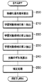
続いて、本発明の特徴部分について説明する。本実施形態では、車両制御装置を実際に使用する際に、上記のように設定される認識使用範囲93を車速もしくは先行車両と自車両との車間距離に応じて切り替えるようにしている。この切り替えは、レーザレーダCPU70によって実行される認識使用範囲切り替え処理に従って行われる。図16に、この認識使用範囲切り替え処理のフローチャートを示し、この図を参照して認識使用範囲93の切り替えについて説明する。
Then, the characteristic part of this invention is demonstrated. In the present embodiment, when the vehicle control device is actually used, the recognized
図16におけるステップ200では、車速および車間距離の取得処理が実行される。ここでいう車速は、車速センサ7からの検出信号に基づいて車速演算ブロック47で演算された車速を意味しており、認識・車間制御ECU3から取得される。また、車間距離に関しては、レーザレーダCPU70で測距された物体のうち、先行車判定ブロック53で先行車両と判定されたものの車間距離(距離Z)を意味しており、それに該当する物体の測距データが認識・車間制御ECU3から取得される。
In
そして、ステップ210では、ステップ200で取得された車速が所定車速(例えば、30km/h)よりも低い低速状態であることと、車間距離が所定値(例えば、30m)よりも短い近距離状態であることの少なくとも一方が成立するか否かが判定される。すなわち、渋滞時のような低速状態のときには先行車両との車間距離が短くなり易く、トラック等と自車両との距離が近づいて、レーザ光がリフレクタに当たらなくなり、突然距離検出が行えなくなる可能性がある。また、実際に測距された車間距離が短く、近距離状態である場合には、同様に距離検出が行えなくなる可能性がある。
In
したがって、このステップで否定判定された場合には、自車両も低速状態ではなく、先行車両に対して近距離状態でもないため、認識使用範囲93の切り替えの必要性は無いものとして、ステップ220に進む。この場合、ステップ220において、レーザレーダCPU70に記憶された認識使用範囲93に相当する面番号、例えば本実施形態の場合には面番号4、5、6におけるポリゴンミラー73の側面を用いたスキャニングがそのまま維持されることになる。このため、ポリゴンミラー73のうち面番号4、5、6の側面が車両前方側に向いたときにレーザダイオード75からレーザ光が照射され、面番号4、5、6の側面の面倒れ角に応じた角度で車両前方にレーザ光が照射される。
Therefore, if a negative determination is made in this step, it is determined that there is no need to switch the
一方、ステップ210で肯定判定された場合には、ステップ230に進んで、認識使用範囲93の切り替えが実行される。
On the other hand, if an affirmative determination is made in
具体的には、ステップ230では、レーザレーダCPU70に記憶された認識使用範囲93に相当する面番号から1つ減らした面番号におけるポリゴンミラー73の側面を用いたスキャニングが実行される。例えば、本実施形態のように面番号4、5、6がレーザレーダCPU70に記憶されていたとすると、その面番号を1つ小さくした面番号3、4、5におけるポリゴンミラー73の側面がスキャニングに用いられる。
Specifically, in
したがって、この場合には、ポリゴンミラー73のうち面番号3〜5の側面が車両前方側に向いたときにレーザダイオード75からレーザ光が照射され、面番号3〜5の側面の面倒れ角に応じた角度で車両前方にレーザ光が照射される。
Therefore, in this case, when the side surface of the surface number 3-5 of the
これら、認識使用範囲93の切り替えを実行していない場合と実行した場合それぞれにおけるレーザ光の照射角度を図17(a)、(b)に示す。
FIGS. 17A and 17B show the irradiation angles of the laser light when the
図17(a)に示されるように、認識使用範囲93の切り替えを実行していない場合には、ポリゴンミラー73における面番号4、5、6の側面で反射されたレーザ光が用いられる。すなわち、通常走行時には、高速走行時などのように遠距離に存在する物体の検知も必要とされる場合に対応できるように、基準角度ΔAを含む面番号5のレーザ光がY軸中心レーザ光とされる。そして、Y軸中心レーザ光の照射角度が、道路の凹凸等による車両のピッチング振動によって変化することを考慮し、それに対応できるように、Y軸中心レーザ光の両側となる面番号4及び6のレーザ光が認識使用範囲93に含められる。
As shown in FIG. 17A, when the switching of the
これに対し、図17(b)に示されるように、認識使用範囲93の切り替えを実行した場合には、ポリゴンミラー73における面番号4、5、6の側面で反射されたレーザ光が用いられる。すなわち、最低限、基準角度ΔAを含む面番号5のレーザ光が車両前方に照射されるようにしつつ、トラック等と自車両との距離が近づいて、レーザ光がリフレクタに当たらなくなることを考慮して、通常走行時に設定された認識使用範囲93よりも上方位置もレーザ光が照射されるように、面番号3及び4のレーザ光が認識使用範囲93に含められる。
On the other hand, as shown in FIG. 17B, when the
なお、一旦、低速状態もしくは近距離状態となって面番号3、4、5に切り替えられたとしても、その後、低速状態および近距離状態が解消された場合には、再びステップ220に進むことになる。この場合には、再度、通常走行時の認識使用範囲93に戻すべく、通常走行時の認識使用範囲93に相当する面番号としてレーザレーダCPU70に記憶されたものに切り替えられる。
Even if the low speed state or the short distance state is entered and the
このように、本実施形態では、低速状態もしくは近距離状態であることが検出された場合に、通常走行時の場合と比べて上方にレーザ光が照射されるようにしている。このため、トラック等と自車両との距離が近づいたとしても、レーザ光が上方に照射され、高い位置のリフレクタに当たるようにすることが可能となる。 As described above, in the present embodiment, when it is detected that the vehicle is in the low speed state or the short distance state, the laser beam is irradiated upward as compared with the case of normal traveling. For this reason, even if the distance between the truck or the like and the host vehicle becomes short, the laser beam can be irradiated upward and hit the reflector at a high position.
したがって、トラック等と自車両との距離が近づいて、レーザ光がリフレクタに当たらなくなり、突然距離検出が正確に行えなくなるという状態を防ぐことができる。 Therefore, it is possible to prevent a situation in which the distance between the truck and the own vehicle approaches and the laser light does not hit the reflector and the distance detection cannot be performed suddenly.
そして、このようなレーザ光を上方に向けて照射することをレーザレーダセンサ5の機械的な構成を従来の構成から何ら変更することなく、ソフト的な手段によって実行できるようにしている。このため、従来の構造のレーザレーダセンサ5をそのまま用いて、上記効果を得ることが可能となる。
Further, the laser beam can be irradiated by such a software means without changing the mechanical configuration of the
なお、本実施形態では、レーザレーダセンサ5の装着角度の調整をメカ調整およびソフト調整によって行い、大まかな調整をメカ調整によって行った後、ソフト調整を行うという説明を行った。これにより、上述したように、例えば、ポリゴンミラー73の各側面のうち認識使用範囲93に相当する面として面番号4、5、6が記憶されるようになっている。しかしながら、ポリゴンミラー73の各側面のうち認識使用範囲93に相当するものの面番号が1、2、3となった場合には、面番号1で反射されたレーザ光よりも上方にレーザ光を照射することができなくなる。このため、メカ調整では、少なくとも認識使用範囲93に相当する面として面番号2〜6の中から3つが選択される程度に、調整を行う必要がある。ただし、この程度の精度にメカ調整をするのは煩雑な作業を要するものではないため、作業時間が長時間になるという影響はない。
In this embodiment, the mounting angle of the
(他の実施形態)
なお、本発明はこのような実施形態に何等限定されるものではなく、本発明の主旨を逸脱しない範囲において種々なる形態で実施し得る。
(Other embodiments)
In addition, this invention is not limited to such embodiment at all, and can be implemented with various forms in the range which does not deviate from the main point of this invention.
(1)上記実施形態では、面番号1〜6にかけて面番号が増加するにつれてレーザ光が徐々に下方にずれていくような場合について説明している。このため、低速状態や近距離状態のときに、認識使用範囲93に相当する面番号としてレーザレーダCPU70に記憶されたものから面番号を1つ減らしたものを用いるようにしている。
(1) In the above embodiment, a case is described in which the laser beam gradually shifts downward as the surface number increases from
しかしながら、面番号1〜6にかけて面番号が増加するにつれてレーザ光が徐々に上方にずれていくように面番号が付けてある場合もある。例えば、ポリゴンミラー73における各側面が上方に向くようにレーザレーダセンサ5が車両に搭載される場合(正転搭載)と、ポリゴンミラー73における各側面が下方に向くようにレーザレーダセンサ5が車両に搭載される場合(反転搭載)とで、面番号とレーザ光の照射高さとの関係が逆になる場合がある。
However, in some cases, the surface numbers are attached so that the laser light gradually shifts upward as the surface numbers increase from
このような場合には、低速状態や近距離状態のときに、例えば、認識使用範囲93に相当する面番号としてレーザレーダCPU70に記憶されたものから面番号を1つ増やしたものを用いるようにすれば、通常走行時と比べて上方にレーザ光を照射させることが可能である。
In such a case, in a low speed state or a short distance state, for example, a surface number that is increased by one from the surface number stored in the
(2)上記実施形態では、低速状態や近距離状態のときに、認識使用範囲93に相当する面番号としてレーザレーダCPU70に記憶されたものから面番号を1つ減少もしくは増加したものを例に挙げて説明した。しかしながら、通常走行時に認識使用範囲93として設定される面番号で照射されるレーザ光よりも上方にレーザ光を照射させることが可能な面番号のものを含むように、認識使用範囲93を切り替えるものであれば、どの面番号であっても構わない。
(2) In the above embodiment, an example in which the surface number is reduced or increased by one from the surface number stored in the
また、低速状態や近距離状態においても、基準角度ΔAを含む面番号を利用したスキャニングを行うようにしているが、必ずしも含んでいなくても良い。ただし、低速状態や近距離状態でも、ある程度は遠距離に存在する物体の検知を行えるように、基準角度ΔAを含む面番号を利用したスキャニングを行うのが好ましい。 Also, scanning is performed using the surface number including the reference angle ΔA even in a low speed state or a short distance state, but it is not always necessary to include it. However, it is preferable to perform scanning using the surface number including the reference angle ΔA so that an object existing at a long distance can be detected to some extent even in a low speed state or a short distance state.
(3)上記実施形態においては、X軸及びY軸方向とも、レーザレーダセンサ5の装着角度の公差範囲に余裕を持たせ、ターゲット100を用いて、X軸及びY軸において受光強度の最も高いレーザ光を中心として認識使用範囲93を設定していた。しかしながら、例えば一方の軸(X軸もしくはY軸)に関しては、装着角度の公差範囲を狭くし、他方の軸方向においてのみ、ターゲット100を用いて認識使用範囲93を設定するようにしても良い。この場合も、従来技術と比較した場合、レーザレーダセンサ5の装着角度の調整作業の負担を軽減することができる。
(3) In the above embodiment, the tolerance range of the mounting angle of the
(4)上記実施形態では、レーザ光の2次元スキャンを行なうために面倒れ角が異なるポリゴンミラー73を用いたが、例えば車幅方向にスキャン可能なガルバノミラーを用い、そのミラー面の倒れ角を変更可能な機構を用いても同様に実現できる。但し、ポリゴンミラー73の場合には、回転駆動だけで2次元スキャンが実現できるという利点がある。
(4) In the above embodiment, the
(5)上記実施形態では、レーザレーダセンサ5内部において、距離及び対応するスキャン角度θx,θyを極座標系からXYZ直交座標系に変換していたが、その処理を物体認識ブロック43において行っても良い。
(5) In the above embodiment, the distance and the corresponding scan angles θx, θy are converted from the polar coordinate system to the XYZ orthogonal coordinate system in the
(6)上記実施形態ではレーザ光を用いたレーザレーダセンサ5を採用したが、ミリ波等の電波や超音波等を用いるものであってもよい。また、スキャン方式にこだわる必要はなく、距離以外に方位を測定できる方式であればよい。そして、例えばミリ波でFMCWレーダ又はドップラーレーダなどを用いた場合には、反射波(受信波)から先行車までの距離情報と先行車の相対速度情報が一度に得られるため、レーザ光を用いた場合のように、距離情報に基づいて相対速度を算出するという過程は不要となる。
(6) Although the
なお、各図中に示したステップは、各種処理を実行する手段に対応するものである。 The steps shown in each figure correspond to means for executing various processes.
1…車両制御装置、3…認識・車間制御ECU、5…レーザレーダセンサ、7…車速センサ、70…レーザレーダCPU、71…発光レンズ、72…スキャナ、73…ポリゴンミラー、74…モータ駆動回路、75…半導体レーザダイオード、76…レーザダイオード駆動回路、81…受光レンズ、83…受光素子。
DESCRIPTION OF
Claims (8)
前記認識使用範囲を設定し、前記スキャン手段から前記認識使用範囲において前記送信波が照射されるようにする認識使用範囲設定手段(30)と、
前記レーダユニットの送受信結果に基づいて、前記反射物体を認識する認識手段(3)とを備えた車両用物体認識装置において、
前記車両の車速を検出する車速検出手段(47)と、
前記車速検出手段によって検出された車速が所定車速よりも小さい低速状態のときに、前記認識使用範囲の切り替えを行い、この切り替え以前に設定されていた前記認識使用範囲よりも前記車両の上方に前記送信波が照射されるように、前記スキャン手段にて照射可能な前記複数の角度範囲から新たな認識使用範囲を設定する認識使用範囲切替手段(200〜230)と、を備えていることを特徴とする車両用物体認識装置。 In the vehicle height direction, it has scanning means (73) capable of irradiating a transmission wave over a plurality of angle ranges, and the recognition use set from the plurality of angle ranges irradiable by the scanning means A radar unit (5) for irradiating the transmission wave in a range (93) and receiving the reflected wave of the transmission wave at a reflecting object;
A recognition usage range setting means (30) for setting the recognition usage range and irradiating the transmission wave in the recognition usage range from the scanning means;
In a vehicle object recognition device comprising a recognition means (3) for recognizing the reflection object based on a transmission / reception result of the radar unit,
Vehicle speed detection means (47) for detecting the vehicle speed of the vehicle;
When the vehicle speed detected by the vehicle speed detection means is in a low speed state lower than a predetermined vehicle speed, the recognition usage range is switched, and the recognition usage range set before the switching is above the vehicle. Recognizing / using range switching means (200 to 230) for setting a new recognizing / using range from the plurality of angle ranges that can be irradiated by the scanning means so that a transmission wave is emitted. A vehicle object recognition device.
前記認識使用範囲切替手段は、前記先行車判定手段によって検出された前記先行車両までの車間距離が所定値よりも小さい近距離状態のときに、前記認識使用範囲の切り替えを行い、この切り替え以前に設定されていた前記認識使用範囲よりも前記車両の上方に前記送信波が照射されるように、前記スキャン手段にて照射可能な前記複数の角度範囲から新たな認識使用範囲を設定するようになっていることを特徴とする請求項1に記載の車両用物体認識装置。 A preceding vehicle determining means (53) for determining that the reflecting object recognized by the recognizing means is a preceding vehicle, and determining an inter-vehicle distance (Z) to the preceding vehicle;
The recognized use range switching means switches the recognized use range when the inter-vehicle distance to the preceding vehicle detected by the preceding vehicle determining means is a short distance state smaller than a predetermined value. A new recognition and use range is set from the plurality of angle ranges that can be irradiated by the scanning means so that the transmission wave is irradiated above the vehicle to the recognition and use range that has been set. The vehicle object recognition device according to claim 1, wherein:
前記認識使用範囲を設定し、前記スキャン手段から前記認識使用範囲において前記送信波が照射されるようにする認識使用範囲設定手段(30)と、
前記レーダユニットの送受信結果に基づいて、前記反射物体を認識する認識手段(3)とを備えた車両用物体認識装置において、
前記認識手段によって認識された反射物体が先行車両であることを判定すると共に、前記先行車両までの車間距離(Z)を求める先行車判定手段(53)と、
前記先行車判定手段によって検出された前記先行車両までの車間距離が所定値よりも小さい近距離状態のときに、前記認識使用範囲の切り替えを行い、この切り替え以前に設定されていた前記認識使用範囲よりも前記車両の上方に前記送信波が照射されるように、前記スキャン手段にて照射可能な前記複数の角度範囲から新たな認識使用範囲を設定する認識使用範囲切替手段(200〜230)と、を備えていることを特徴とする車両用物体認識装置。 In the vehicle height direction, it has scanning means (73) capable of irradiating a transmission wave over a plurality of angle ranges, and the recognition use set from the plurality of angle ranges irradiable by the scanning means A radar unit (5) for irradiating the transmission wave in a range (93) and receiving the reflected wave of the transmission wave at a reflecting object;
A recognition usage range setting means (30) for setting the recognition usage range and irradiating the transmission wave in the recognition usage range from the scanning means;
In a vehicle object recognition device comprising a recognition means (3) for recognizing the reflection object based on a transmission / reception result of the radar unit,
A preceding vehicle determining means (53) for determining that the reflecting object recognized by the recognizing means is a preceding vehicle, and obtaining an inter-vehicle distance (Z) to the preceding vehicle;
The recognition usage range is switched when the inter-vehicle distance to the preceding vehicle detected by the preceding vehicle determination means is in a short distance state smaller than a predetermined value, and the recognition usage range set before this switching is performed. Recognizing / using range switching means (200 to 230) for setting a new recognizing / using range from the plurality of angle ranges that can be irradiated by the scanning means so that the transmission wave is irradiated above the vehicle. And a vehicle object recognition device.
前記認識使用範囲設定手段は、前記多面ミラーの各側面の面倒れ角に応じた面番号を記憶し、前記多面ミラーの各側面のうち前記認識使用範囲に相当する面番号のもので前記送信波を反射させることにより、前記認識使用範囲における前記送信波の照射を行うようになっており、
前記認識使用範囲切替手段は、前記多面ミラーの各側面のうち前記認識使用範囲設定手段に記憶された面番号のものと比べ、前記送信波が前記車両の上方に照射されるものの面番号を前記新たな認識使用範囲に相当する面番号として、前記多面ミラーにおける切り替え後の面番号の各側面で前記送信波が照射されるようにすることを特徴とする請求項1ないし3のいずれか1つに記載の車両用物体認識装置。 The scanning means is a multi-faceted mirror having a plurality of side surfaces with different plane tilt angles, and reflects the transmission wave on each side face of the multi-faced mirror so as to irradiate the transmission wave in the height direction of the vehicle. And
The recognized use range setting means stores a surface number corresponding to a surface tilt angle of each side surface of the multifaceted mirror, and has a surface number corresponding to the recognized use range among the side faces of the multifaceted mirror. By reflecting the transmission wave in the recognized use range,
The recognized usage range switching means compares the surface number of the surface number of the transmission wave irradiated above the vehicle with respect to the surface number stored in the recognized usage range setting means among the side surfaces of the multi-faced mirror. 4. The transmission wave according to claim 1, wherein the transmission wave is irradiated on each side face of the face number after switching in the multi-faced mirror as a face number corresponding to a new recognition usage range. The vehicle object recognition device described in 1.
前記認識使用範囲切替手段は、切り替え前の前記認識使用範囲に相当する面番号と比べて、前記送信波を前記車両の高さ方向の上方にする面番号に切り替えるようになっていることを特徴とする請求項4に記載の車両用物体認識装置。 Each side surface of the multi-sided mirror is given a surface number in order from the side surface that irradiates the transmission wave to the uppermost position in the height direction of the vehicle.
The recognized usage range switching means is configured to switch to a surface number that makes the transmission wave upward in the height direction of the vehicle, compared to a surface number corresponding to the recognized usage range before switching. The vehicle object recognition device according to claim 4.
前記認識範囲切替手段は、切り替え前の前記認識使用範囲に相当する面番号と比べて、前記送信波を前記車両の高さ方向の上方にする面番号のものと、前記所定の基準角度(ΔA)が含まれる面番号のものとに切り替えるようになっていることを特徴とする請求項5に記載の車両用物体認識装置。 The recognized usage range setting means includes a surface number corresponding to the recognized usage range, a surface number including a predetermined reference angle (ΔA) with respect to the front direction of the vehicle, and surfaces on both sides of the surface number. Set three of the numbers,
The recognition range switching means has a surface number that makes the transmission wave upward in the height direction of the vehicle compared to a surface number corresponding to the recognition use range before switching, and the predetermined reference angle (ΔA The vehicle object recognition device according to claim 5, wherein the object number is switched to one having a surface number that includes ().
前記認識使用範囲切替手段は、切り替え前の前記認識使用範囲に相当する面番号に対して、面番号を1つ減少または増加させるようになっていることを特徴とする請求項4または5に記載の車両用物体認識装置。 Each side surface of the multi-sided mirror is given a surface number in order from the side surface that irradiates the transmission wave to the uppermost position in the height direction of the vehicle.
6. The recognized usage range switching means is configured to decrease or increase a surface number by one with respect to a surface number corresponding to the recognized usage range before switching. Vehicle object recognition device.
前記認識使用範囲設定手段は、前記各側面のうち面番号が連続する所定個数を前記認識使用範囲に相当するものとして設定し、
前記認識範囲切替手段は、切り替え前の前記認識使用範囲に相当する複数の連続した面番号それぞれに対して、面番号を1つ減少または増加させるようになっていることを特徴とする請求項4または5に記載の車両用物体認識装置。
Each side surface of the multi-sided mirror is given a surface number in order from the side surface that irradiates the transmission wave to the uppermost position in the height direction of the vehicle,
The recognized usage range setting means sets a predetermined number of consecutive surface numbers among the side surfaces as equivalent to the recognized usage range,
5. The recognition range switching unit is configured to decrease or increase a surface number by one for each of a plurality of consecutive surface numbers corresponding to the recognition usage range before switching. Or the object recognition device for a vehicle according to 5.
Priority Applications (3)
| Application Number | Priority Date | Filing Date | Title |
|---|---|---|---|
| JP2004104120A JP2005291788A (en) | 2004-03-31 | 2004-03-31 | Vehicle object recognition device |
| US11/093,836 US20050219506A1 (en) | 2004-03-31 | 2005-03-30 | Object recognition device for vehicle |
| DE102005014721A DE102005014721A1 (en) | 2004-03-31 | 2005-03-31 | Object recognition device for vehicles |
Applications Claiming Priority (1)
| Application Number | Priority Date | Filing Date | Title |
|---|---|---|---|
| JP2004104120A JP2005291788A (en) | 2004-03-31 | 2004-03-31 | Vehicle object recognition device |
Publications (1)
| Publication Number | Publication Date |
|---|---|
| JP2005291788A true JP2005291788A (en) | 2005-10-20 |
Family
ID=35034293
Family Applications (1)
| Application Number | Title | Priority Date | Filing Date |
|---|---|---|---|
| JP2004104120A Pending JP2005291788A (en) | 2004-03-31 | 2004-03-31 | Vehicle object recognition device |
Country Status (3)
| Country | Link |
|---|---|
| US (1) | US20050219506A1 (en) |
| JP (1) | JP2005291788A (en) |
| DE (1) | DE102005014721A1 (en) |
Cited By (7)
| Publication number | Priority date | Publication date | Assignee | Title |
|---|---|---|---|---|
| WO2013146375A1 (en) * | 2012-03-28 | 2013-10-03 | 株式会社デンソー | Vehicle-mounted radar device and target detection method thereof |
| JP2018059847A (en) * | 2016-10-06 | 2018-04-12 | オムロンオートモーティブエレクトロニクス株式会社 | Laser radar equipment |
| WO2019138964A1 (en) * | 2018-01-09 | 2019-07-18 | パイオニア株式会社 | Control device, scanning device, control method, program, and storage medium |
| JP2021148562A (en) * | 2020-03-18 | 2021-09-27 | 株式会社Soken | Radar device |
| CN115201830A (en) * | 2022-07-18 | 2022-10-18 | 深圳绿米联创科技有限公司 | Target object detection method and device and intelligent door lock |
| US11525891B2 (en) * | 2019-07-08 | 2022-12-13 | Lg Electronics Inc. | System for identifying vehicle using laser sensor |
| WO2022270103A1 (en) * | 2021-06-23 | 2022-12-29 | 株式会社デンソー | Optical axis adjustment method, laser radar device, and optical axis adjustment system |
Families Citing this family (25)
| Publication number | Priority date | Publication date | Assignee | Title |
|---|---|---|---|---|
| JP2005043080A (en) * | 2003-07-23 | 2005-02-17 | Fujitsu Ten Ltd | Method of attaching radar for vehicle, and radar for vehicle |
| JP4846545B2 (en) * | 2006-11-29 | 2011-12-28 | 株式会社デンソー | Driving assistance device |
| JP5152840B2 (en) * | 2007-11-07 | 2013-02-27 | オムロンオートモーティブエレクトロニクス株式会社 | Automotive radar equipment |
| KR20140019501A (en) * | 2012-08-06 | 2014-02-17 | 현대자동차주식회사 | Method for producing classification for recognizing object |
| EP2735887B1 (en) * | 2012-11-22 | 2015-06-03 | Sick Ag | Optical recording device |
| DE102013011853A1 (en) * | 2013-07-16 | 2015-01-22 | Valeo Schalter Und Sensoren Gmbh | Optoelectronic detection device and method for scanning the environment of a motor vehicle |
| KR101550972B1 (en) * | 2013-09-25 | 2015-09-07 | 현대자동차주식회사 | Apparatus and Method for Extracting of Feature Point for Recognize of Obstacle using Laser Scanner |
| KR101632873B1 (en) * | 2014-09-05 | 2016-07-01 | 현대모비스 주식회사 | System and method for detecting obstacles |
| US20190187259A1 (en) * | 2016-08-31 | 2019-06-20 | Pioneer Corporation | Measuring device, control device, control method, and program |
| WO2018176115A1 (en) * | 2017-03-31 | 2018-10-04 | Huawei Technologies Co., Ltd. | Apparatus and method for scanning and ranging with eye-safe pattern |
| US11460550B2 (en) | 2017-09-19 | 2022-10-04 | Veoneer Us, Llc | Direct detection LiDAR system and method with synthetic doppler processing |
| US11194022B2 (en) | 2017-09-29 | 2021-12-07 | Veoneer Us, Inc. | Detection system with reflection member and offset detection array |
| US11585901B2 (en) | 2017-11-15 | 2023-02-21 | Veoneer Us, Llc | Scanning lidar system and method with spatial filtering for reduction of ambient light |
| US11977185B1 (en) * | 2019-04-04 | 2024-05-07 | Seyond, Inc. | Variable angle polygon for use with a LiDAR system |
| US11579257B2 (en) | 2019-07-15 | 2023-02-14 | Veoneer Us, Llc | Scanning LiDAR system and method with unitary optical element |
| US11474218B2 (en) | 2019-07-15 | 2022-10-18 | Veoneer Us, Llc | Scanning LiDAR system and method with unitary optical element |
| US11313969B2 (en) | 2019-10-28 | 2022-04-26 | Veoneer Us, Inc. | LiDAR homodyne transceiver using pulse-position modulation |
| JP7401273B2 (en) * | 2019-11-26 | 2023-12-19 | 日立Astemo株式会社 | Mobile body control device and method |
| US12044800B2 (en) | 2021-01-14 | 2024-07-23 | Magna Electronics, Llc | Scanning LiDAR system and method with compensation for transmit laser pulse effects |
| US11326758B1 (en) | 2021-03-12 | 2022-05-10 | Veoneer Us, Inc. | Spotlight illumination system using optical element |
| WO2022225859A1 (en) | 2021-04-22 | 2022-10-27 | Innovusion, Inc. | A compact lidar design with high resolution and ultra-wide field of view |
| US11732858B2 (en) | 2021-06-18 | 2023-08-22 | Veoneer Us, Llc | Headlight illumination system using optical element |
| US12228653B2 (en) | 2022-10-07 | 2025-02-18 | Magna Electronics, Llc | Integrating a sensing system into headlight optics |
| US12092278B2 (en) | 2022-10-07 | 2024-09-17 | Magna Electronics, Llc | Generating a spotlight |
| US12202396B1 (en) | 2023-12-19 | 2025-01-21 | Magna Electronics, Llc | Line-scan-gated imaging for LiDAR headlight |
Family Cites Families (4)
| Publication number | Priority date | Publication date | Assignee | Title |
|---|---|---|---|---|
| JP3259475B2 (en) * | 1993-10-27 | 2002-02-25 | ミノルタ株式会社 | Distance measuring device |
| JP2000147124A (en) * | 1998-11-12 | 2000-05-26 | Denso Corp | In-vehicle radar device |
| JP3772969B2 (en) * | 2001-10-16 | 2006-05-10 | オムロン株式会社 | Automotive radar equipment |
| JP2003149338A (en) * | 2001-11-09 | 2003-05-21 | Denso Corp | Object recognition device and distance measurement device |
-
2004
- 2004-03-31 JP JP2004104120A patent/JP2005291788A/en active Pending
-
2005
- 2005-03-30 US US11/093,836 patent/US20050219506A1/en not_active Abandoned
- 2005-03-31 DE DE102005014721A patent/DE102005014721A1/en not_active Withdrawn
Cited By (8)
| Publication number | Priority date | Publication date | Assignee | Title |
|---|---|---|---|---|
| WO2013146375A1 (en) * | 2012-03-28 | 2013-10-03 | 株式会社デンソー | Vehicle-mounted radar device and target detection method thereof |
| JP2018059847A (en) * | 2016-10-06 | 2018-04-12 | オムロンオートモーティブエレクトロニクス株式会社 | Laser radar equipment |
| WO2019138964A1 (en) * | 2018-01-09 | 2019-07-18 | パイオニア株式会社 | Control device, scanning device, control method, program, and storage medium |
| US11525891B2 (en) * | 2019-07-08 | 2022-12-13 | Lg Electronics Inc. | System for identifying vehicle using laser sensor |
| JP2021148562A (en) * | 2020-03-18 | 2021-09-27 | 株式会社Soken | Radar device |
| JP7477329B2 (en) | 2020-03-18 | 2024-05-01 | 株式会社Soken | Axis offset estimation device |
| WO2022270103A1 (en) * | 2021-06-23 | 2022-12-29 | 株式会社デンソー | Optical axis adjustment method, laser radar device, and optical axis adjustment system |
| CN115201830A (en) * | 2022-07-18 | 2022-10-18 | 深圳绿米联创科技有限公司 | Target object detection method and device and intelligent door lock |
Also Published As
| Publication number | Publication date |
|---|---|
| US20050219506A1 (en) | 2005-10-06 |
| DE102005014721A1 (en) | 2005-10-20 |
Similar Documents
| Publication | Publication Date | Title |
|---|---|---|
| JP4428208B2 (en) | Vehicle object recognition device | |
| US20050219506A1 (en) | Object recognition device for vehicle | |
| JP3405327B2 (en) | Object recognition method and apparatus, recording medium | |
| US6018308A (en) | Obstacle recognition system for automotive vehicle | |
| US6927699B2 (en) | Object recognition apparatus for vehicle, and inter-vehicle distance control unit | |
| US7136753B2 (en) | Object recognition apparatus for vehicle, inter-vehicle control apparatus, and distance measurement apparatus | |
| JP3736521B2 (en) | Vehicle object recognition device | |
| JP3331882B2 (en) | Central axis deflection amount calculating device, central axis deflection amount correcting device, and inter-vehicle control device of vehicle obstacle detection device | |
| JP4793094B2 (en) | Driving environment recognition device | |
| US6484087B2 (en) | Method of selecting a preceding vehicle, a preceding vehicle selecting apparatus, and a recording medium for selecting a preceding vehicle | |
| JP3941795B2 (en) | Leading vehicle recognition device | |
| JP3915742B2 (en) | Vehicle object recognition device | |
| JP2004184331A (en) | Vehicle object recognition device | |
| JP3736520B2 (en) | Obstacle recognition device for vehicles | |
| US8810445B2 (en) | Method and apparatus for recognizing presence of objects | |
| JP2005077379A (en) | Radar equipment | |
| JP2004177350A (en) | Radar equipment for vehicles | |
| JP3427817B2 (en) | Vehicle obstacle recognition method and apparatus, recording medium | |
| JP3757937B2 (en) | Distance measuring device | |
| CN115315634B (en) | Shaft misalignment estimation device | |
| JP3841047B2 (en) | Vehicle distance control device | |
| JP3941791B2 (en) | Vehicle object recognition apparatus and program | |
| JP5556317B2 (en) | Object recognition device | |
| JP2002131433A (en) | Object recognition method and apparatus | |
| JP3514166B2 (en) | Preceding vehicle recognition device |
Legal Events
| Date | Code | Title | Description |
|---|---|---|---|
| A621 | Written request for application examination |
Free format text: JAPANESE INTERMEDIATE CODE: A621 Effective date: 20060523 |
|
| A871 | Explanation of circumstances concerning accelerated examination |
Free format text: JAPANESE INTERMEDIATE CODE: A871 Effective date: 20061010 |
|
| A975 | Report on accelerated examination |
Free format text: JAPANESE INTERMEDIATE CODE: A971005 Effective date: 20061027 |
|
| A131 | Notification of reasons for refusal |
Free format text: JAPANESE INTERMEDIATE CODE: A131 Effective date: 20061114 |
|
| A521 | Request for written amendment filed |
Free format text: JAPANESE INTERMEDIATE CODE: A523 Effective date: 20070109 |
|
| A02 | Decision of refusal |
Free format text: JAPANESE INTERMEDIATE CODE: A02 Effective date: 20070206 |