JP2005291831A - Imaging flow site meter - Google Patents
Imaging flow site meter Download PDFInfo
- Publication number
- JP2005291831A JP2005291831A JP2004105332A JP2004105332A JP2005291831A JP 2005291831 A JP2005291831 A JP 2005291831A JP 2004105332 A JP2004105332 A JP 2004105332A JP 2004105332 A JP2004105332 A JP 2004105332A JP 2005291831 A JP2005291831 A JP 2005291831A
- Authority
- JP
- Japan
- Prior art keywords
- imaging
- image
- flow
- unit
- cell
- Prior art date
- Legal status (The legal status is an assumption and is not a legal conclusion. Google has not performed a legal analysis and makes no representation as to the accuracy of the status listed.)
- Pending
Links
- 238000003384 imaging method Methods 0.000 title claims abstract description 181
- 239000002245 particle Substances 0.000 claims abstract description 59
- 239000007788 liquid Substances 0.000 claims abstract description 25
- 210000004027 cell Anatomy 0.000 claims description 88
- 230000003287 optical effect Effects 0.000 claims description 74
- 238000002073 fluorescence micrograph Methods 0.000 claims description 21
- 238000005286 illumination Methods 0.000 claims description 18
- 210000003855 cell nucleus Anatomy 0.000 claims description 9
- 238000006073 displacement reaction Methods 0.000 claims description 7
- 239000007850 fluorescent dye Substances 0.000 claims description 2
- 239000000523 sample Substances 0.000 description 56
- 238000012545 processing Methods 0.000 description 8
- 230000033001 locomotion Effects 0.000 description 5
- 210000004940 nucleus Anatomy 0.000 description 5
- 238000010586 diagram Methods 0.000 description 4
- 230000005540 biological transmission Effects 0.000 description 3
- 238000012360 testing method Methods 0.000 description 3
- 238000010276 construction Methods 0.000 description 2
- 229940079593 drug Drugs 0.000 description 2
- 239000003814 drug Substances 0.000 description 2
- 230000002093 peripheral effect Effects 0.000 description 2
- 239000012488 sample solution Substances 0.000 description 2
- 230000003321 amplification Effects 0.000 description 1
- 238000004458 analytical method Methods 0.000 description 1
- 239000002246 antineoplastic agent Substances 0.000 description 1
- 229940041181 antineoplastic drug Drugs 0.000 description 1
- 238000013459 approach Methods 0.000 description 1
- 238000012937 correction Methods 0.000 description 1
- 230000000694 effects Effects 0.000 description 1
- 238000012632 fluorescent imaging Methods 0.000 description 1
- 239000011521 glass Substances 0.000 description 1
- 238000000034 method Methods 0.000 description 1
- 238000003199 nucleic acid amplification method Methods 0.000 description 1
- 239000012466 permeate Substances 0.000 description 1
- 239000012780 transparent material Substances 0.000 description 1
Images
Landscapes
- Investigating, Analyzing Materials By Fluorescence Or Luminescence (AREA)
Abstract
Description
この発明はイメージングフローサイトメータに関し、特に、フローセル中を流れる粒子を撮像する機能を備えたフローサイトメータに関する。 The present invention relates to an imaging flow cytometer, and more particularly to a flow cytometer having a function of imaging particles flowing in a flow cell.
この発明の背景技術としては、被検粒子を含む液体をフローセルに流してサンプル流を形成し、サンプル流をレーザ光で照明して、照明された粒子の蛍光像と透過光像をそれぞれ2つの撮像部(イメージセンサ)で撮像するようにしたものが知られている(例えば、特許文献1参照)。
しかしながら、このような従来の装置においては、被検粒子が周りの媒質より高い屈折率をもつ細胞のような透明物体の場合には、透過光像がほとんど消失し、コントラストの良い透過光画像を得ることが難しかった。
この発明はこのような事情を考慮してなされたもので、透過光画像の撮像系の焦点を、正確な焦点から適度にずらして設定することにより、コントラストの良好な透過光画像を得ることが可能なイメージングフローサイトメータを提供するものである。
However, in such a conventional apparatus, when the test particle is a transparent object such as a cell having a higher refractive index than the surrounding medium, the transmitted light image is almost lost, and a transmitted light image with good contrast is obtained. It was difficult to get.
The present invention has been made in consideration of such circumstances. By setting the focus of the imaging system of the transmitted light image to be appropriately shifted from the accurate focus, a transmitted light image with good contrast can be obtained. A possible imaging flow cytometer is provided.
この発明は、粒子含有液をシース液で包んで試料流を形成するシースフローセルと、試料流を照明する光源と、試料流中の粒子の透過光画像を撮像する第1撮像部と、試料流中の粒子の蛍光画像を撮像する第2撮像部とを備え、第1撮像部が後ピンの透過光画像を撮像するイメージングフローサイトメータを提供するものである。 The present invention includes a sheath flow cell that wraps a particle-containing liquid with a sheath liquid to form a sample flow, a light source that illuminates the sample flow, a first imaging unit that captures a transmitted light image of particles in the sample flow, and a sample flow And a second imaging unit that captures a fluorescent image of the particles inside, and the first imaging unit provides an imaging flow cytometer that captures the transmitted light image of the rear pin.
この発明によれば、第1撮像部が試料流中の粒子に対して後ピンの透過光画像を撮像するので、粒子が細胞のような透明な粒子であれば、その画像は黒いベッケ線に包まれて現れる。従って、第1撮像部によりコントラストの良好な透明粒子の透過光画像を得ることができる。また、第2撮像部は、ピントを試料流中の粒子に合わすことにより、粒子の蛍光画像をコントラスト良く撮像できる。 According to the present invention, since the first imaging unit captures the transmitted light image of the rear pin with respect to the particles in the sample flow, if the particles are transparent particles such as cells, the image becomes a black Becke line. Wrapped up. Therefore, it is possible to obtain a transmitted light image of transparent particles with good contrast by the first imaging unit. In addition, the second imaging unit can capture a fluorescent image of the particles with good contrast by focusing on the particles in the sample flow.
この発明のイメージングフローサイトメータは、粒子含有液をシース液で包んで試料流を形成するシースフローセルと、試料流を照明する光源と、試料流中の粒子の透過光画像を撮像する第1撮像部と、試料流中の粒子の蛍光画像を撮像する第2撮像部とを備え、第1撮像部が後ピンの透過光画像を撮像されていることを特徴とする。 The imaging flow cytometer according to the present invention includes a sheath flow cell that wraps a particle-containing liquid in a sheath liquid to form a sample flow, a light source that illuminates the sample flow, and a first imaging that captures a transmitted light image of particles in the sample flow. And a second imaging unit that captures a fluorescent image of particles in the sample flow, wherein the first imaging unit captures a transmitted light image of the rear pin.
この発明は、別の観点から、粒子含有液をシース液で包んで試料流を形成するシースフローセルと、試料流を照明する光源と、試料流中の粒子の透過光画像を撮像する第1撮像部と、試料流中の粒子の像を第1撮像部の第1撮像面に投影するための第1光学系と、試料流中の粒子の蛍光画像を撮像する第2撮像部と、試料流中の粒子の像を第2撮像部の第2撮像面に投影するための第2光学系とを備え、第1光学系の焦点が第1撮像面よりも遠い位置にあるイメージングフローサイトメータを提供するものである。 According to another aspect of the present invention, a sheath flow cell that wraps a particle-containing liquid with a sheath liquid to form a sample flow, a light source that illuminates the sample flow, and a first imaging that captures a transmitted light image of particles in the sample flow. A first optical system for projecting an image of particles in the sample stream onto the first imaging surface of the first imaging unit, a second imaging unit for capturing a fluorescent image of particles in the sample stream, and a sample stream An imaging flow cytometer comprising: a second optical system for projecting an image of particles therein to the second imaging surface of the second imaging unit, wherein the focal point of the first optical system is farther than the first imaging surface It is to provide.
このイメージングフローサイトメータの被検粒子としては、細胞のようなそのその一部が染色可能な透明粒子が好適であるが、これに限定されない。シースフローセルには流路の断面が偏平型のものが好ましいが、流路の断面が円形や方形のものも用いることができる。
光源には、白色ランプ,レーザ,ストロボフラッシュランプ,パルスレーザなどを用いることができる。
第1および第2撮像部にはCCDカメラ,ビデオカメラなどが好適であるが、とくに蛍光画像を撮像する第2撮像部には、光増幅素子、例えばイメージインテンシファイヤを付設することが好ましい。なお、この発明において「後ピン」とは、被写体の後にピントの合った状態をいう。
As the test particles of this imaging flow cytometer, transparent particles that can be partially stained such as cells are suitable, but are not limited thereto. The sheath flow cell preferably has a flat cross section of the flow path, but a cross section of the flow path can be circular or square.
As the light source, a white lamp, a laser, a strobe flash lamp, a pulse laser, or the like can be used.
A CCD camera, a video camera, or the like is suitable for the first and second imaging units, but it is preferable that an optical amplification element, for example, an image intensifier is attached to the second imaging unit that captures a fluorescent image. In the present invention, the “rear pin” refers to a state in focus after the subject.
試料流中の粒子の像を第2撮像部の第2撮像面に投影するための第2光学系においては、第2光学系の焦点が第2撮像面にあるとが好ましい。
粒子が細胞であり、細胞核が蛍光色素で染色され、蛍光画像が細胞核から得られるようにしてもよい。
光源が、白色光を出射する第1光源と、レーザ光を出射する第2光源からなり、第1および第2撮像部は、それぞれ第1および第2光源により照明された粒子を撮像するようにしてもよい。
第1光源は第1撮像部が透過照明によって粒子を撮像するように配置され、第1光源は第2撮像部が落射照明によって粒子を撮像するように配置されてもよい。
In the second optical system for projecting an image of particles in the sample flow onto the second imaging surface of the second imaging unit, it is preferable that the focus of the second optical system is on the second imaging surface.
The particles may be cells, the cell nucleus may be stained with a fluorescent dye, and a fluorescent image may be obtained from the cell nucleus.
The light source includes a first light source that emits white light and a second light source that emits laser light, and the first and second imaging units respectively capture particles illuminated by the first and second light sources. May be.
The first light source may be arranged such that the first imaging unit images particles by transmitted illumination, and the first light source is arranged so that the second imaging unit images particles by epi-illumination.
光源がパルス光源からなってもよい。
この発明のイメージングフローサイトメータは、第1撮像部によって得られる粒子画像の画像濃度に基づいてシースフローセルの位置を第1撮像部の光軸方向に変位させる制御部をさらに備えてもよい。
制御部がシースフローセルを第1撮像部の光軸方向に変位させる変位部と、第1撮像部による粒子画像の平均画像濃度を算出する演算部と、算出した平均画像濃度が所定値になるように変位部を駆動する駆動制御部を備えてもよい。
The light source may be a pulsed light source.
The imaging flow cytometer of the present invention may further include a control unit that displaces the position of the sheath flow cell in the optical axis direction of the first imaging unit based on the image density of the particle image obtained by the first imaging unit.
A control unit displaces the sheath flow cell in the optical axis direction of the first imaging unit, a calculation unit that calculates the average image density of the particle image by the first imaging unit, and the calculated average image density becomes a predetermined value. A drive control unit for driving the displacement unit may be provided.
この発明は、別の観点から、粒子含有液をシース液に包んで試料流を形成するシースフローセルと、試料流中の粒子の透過光画像および蛍光画像をそれぞれ撮像する第1および第2撮像部とを備え、第1撮像部によって得られる粒子画像の平均画像濃度に基づいてシースフローセルの位置を第1撮像部の光軸に沿って変位させる制御部を備えるイメージングフローサイトメータを提供するものである。 According to another aspect of the present invention, a sheath flow cell that forms a sample flow by wrapping a particle-containing liquid in a sheath liquid, and first and second imaging units that respectively capture a transmitted light image and a fluorescence image of particles in the sample flow. And an imaging flow cytometer comprising a control unit that displaces the position of the sheath flow cell along the optical axis of the first imaging unit based on the average image density of the particle image obtained by the first imaging unit. is there.
この発明は、さらに別の観点から、粒子含有液をシース液に包んで試料流を形成するシースフローセルと、試料流中の粒子の画像を撮像する撮像部と、撮像部によって得られる粒子画像の画像濃度に基づいてシースフローセルの位置を第1撮像部の光軸に沿って変位させる制御部を備えるイメージングフローサイトメータを提供するものである。 According to another aspect of the present invention, a sheath flow cell that wraps a particle-containing liquid in a sheath liquid to form a sample flow, an imaging unit that captures an image of particles in the sample flow, and a particle image obtained by the imaging unit An imaging flow cytometer is provided that includes a control unit that displaces the position of the sheath flow cell along the optical axis of the first imaging unit based on the image density.
実施例
以下、図面に示す実施例に基づいて、この発明を詳述する。これによって、この発明が限定されるものではない。
第1実施例
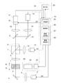
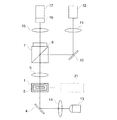
図1はこの発明の第1実施例を示す構成説明図である。同図に示すようにシースフローセル(以下、フローセルという)1は、細長い長方形の断面を有する筒状のセルであり、ガラスやプラスチックのような透明材料で形成される。フローセル1には、試料液とシース液が導入され、試料液はシース液に包まれて約1μm×2000μmの偏平な試料流5に変換される。
EXAMPLES Hereinafter, the present invention will be described in detail based on examples shown in the drawings. This does not limit the present invention.
First Embodiment FIG. 1 is an explanatory diagram showing the construction of a first embodiment of the present invention. As shown in the figure, a sheath flow cell (hereinafter referred to as a flow cell) 1 is a cylindrical cell having an elongated rectangular cross section, and is formed of a transparent material such as glass or plastic. A sample liquid and a sheath liquid are introduced into the
この実施例においては、K562又はHL−60細胞について、1サンプルあたり、2000個/μLの細胞が浮遊する試料液200μL準備し、その試料液を2〜5cm/secの流速でフローセル1に流すようにしている。なお、細胞は細胞核がHochest33342によって予め蛍光染色されている。
In this example, for K562 or HL-60 cells, 200 μL of a sample solution in which 2000 cells / μL of cells are suspended is prepared per sample, and the sample solution is allowed to flow through the
透過画像の撮像系は、試料流5中の細胞を照明するための第1照明光学系と試料流5中の細胞からの光像を受光するための第1受光光学系(第1光学系)からなる。第1照明光学系は、第1光源2、コンデンサレンズ3および反射ミラー4から構成される。第1受光光学系(第1光学系)は、対物レンズ6、ダイクロイックミラー7、蛍光フィルタ8、ハーフミラー9、反射ミラー10、結像レンズ11、および第1撮像部12から構成される。
一方、蛍光画像の撮像系は、試料流5の細胞を照明するための第2照明光学系と試料流5の細胞からの光像を受光するため第2受光光学系(第2光学系)からなる。第2照明光学系は、第2光源13、コンデンサレンズ14、ダイクロイックミラー7および対物レンズ6から構成される。第2受光光学系(第2光学系)は、対物レンズ6、ダイクロイックミラー7、蛍光フィルタ8、ハーフミラー9、結像レンズ15、ゲート付きイメージインテンシファイヤ16、および第2撮像部17から構成される。
The transmission image imaging system includes a first illumination optical system for illuminating cells in the
On the other hand, the imaging system of the fluorescence image includes a second illumination optical system for illuminating the cells of the
ここで、第1光源2は、コンデンサレンズ3を介してケラー照明を行うように設定されたパルス光源であり、これには白色光(波長500nm〜650nm)を出射するストロボフラッシュランプが用いられる。第2光源17は、コンデンサレンズ14を介してクリティカル照明を行うように設定されたパルス光源であり、これには中心波長365nmの紫外光を出射するUVパルスレーザが用いられる。ダイクロイックミラー7には400nm以上の波長の光を透過させ、400nmより短い波長の光を反射するものが用いられる。蛍光フィルタ8は、波長450nm±50nmの波長の光のみを透過させる。また、ハーフミラー9には入射光の1/2の光量を透過させ、残りを反射するものが用いられる。第1および第2撮像部12,17はCCDカメラ(ビデオカメラ)で構成される。
Here, the
次に、制御部21は、信号処理部24,表示部30および変位部29から構成される。変位部29は、ステッピングモータ23と直線移動機構22を備える。直線移動機構22は、ステッピングモータ23の回転出力を減速し直線運動に変換してフローセル1を撮像系の光軸方向(矢印A又はB方向)に変位させる。つまり、ステッピングモータ23に1ステップ分の駆動パルスが印加されると、フローセル1は0.05μmだけ変位するようになっている。
Next, the
信号処理部24は、演算部25,格納部26,駆動制御部27および撮像制御部28を備え、マイクロコンピュータによって一体的に構成される。演算部25は、第1および第2撮像部12,17から得られる画像データを処理して分析に必要な演算を行う。格納部26は、演算部25で処理された画像データや演算された演算結果を格納する。駆動制御部27は、演算部25の演算結果に基づいてステッピングモータ23に駆動パルスを印加し、変位部29を駆動制御する。撮像制御部28は、第1および第2光源2,13の発光動作,インテンシファイヤ16のゲートの開閉動作、そして第1および第2撮像部12,17の撮像動作などを制御する。
The
第1受光光学系の焦点は、第1撮像部12の撮像面よりも遠い位置に合わされ、黒いベッケ線に包まれた透過光画像が得られるように結像レンズ11と撮像部12の間の光路長が設定される。また、第2受光光学系の焦点は、第2撮像部17の撮像面に合うように結像レンズ15と第2撮像部17との光路長が設定され、コントラストの良い蛍光画像が得られる。ここで、対物レンズ6の焦点は、試料流5の中心軸に合うように設定されている。
The focal point of the first light receiving optical system is adjusted to a position farther than the imaging surface of the
このような構成における動作について次に説明する。
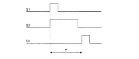
図2は、制御部1の撮像制御部28から出力される信号、つまり第2光源13および第1光源2をそれぞれ点灯させるパルス信号S1,S3と、イメージインテンシファイヤ16のゲートを開くパルス信号S3のタイミングチャートである。
まず、フローセル1に試料流5が形成されると、撮像制御部28から出力されるパルス信号S1によって第2光源13が365nmの波長の光を発光する。第2光源13の出射光はコンデンサレンズ14を通ってダイクロイックミラー7で対物レンズ6の方へ反射され、対物レンズ6を介して試料流5内の細胞を落射照明する。それによって、細胞内の蛍光染色された核から400〜500nmの波長の蛍光が励起され、結像レンズ6,ダイクロイックミラー7,蛍光フィルタ8,ハーフミラー9,および結像レンズ15を介してイメージインテンシファイヤ16へ到達する。この時、イメージインテンシファイヤ16のゲートは、撮像制御部28から出力されるパルス信号S2により、図2に示すように開いているので、核の蛍光画像がイメージインテンシファイヤ16の光電面に結像し、増幅される。増幅された蛍光画像は第2撮像部17によって撮像され、蛍光画像データとして制御部21の信号処理部24へ送られる。
Next, the operation in such a configuration will be described.
2 shows signals output from the
First, when the
図2に示すように、イメージインテンシファイヤ16のゲートを開くパルス信号S2がオフになり、そのゲートが閉じると、次に、撮像制御部28からパルス信号S3が出力され、第1光源2が白色光を発光する。第1光源2の出射光はコンデンサレンズ3および反射ミラー4を介して試料流5内の細胞を照明する。そして、細胞を透過した透過光は、ダイクロイックミラー7,蛍光フィルタ8,ハーフミラー9,反射ミラー10および結像レンズ11を介して第1撮像部12へ入射し、細胞の透過光画像として第1撮像部12により撮像され、透過光画像データとして制御部21の信号処理部24へ送られる。このような第1および第2撮像部12,17による各撮像動作が1秒間に30回くり返される。これによって、1秒間に各30フレームの透過光画像と蛍光画像が得られる。つまり、1秒間に30組の透過光画像と蛍光画像が得られる。なお、各組の画像において同じ細胞の透過光画像と蛍光画像の位置ずれが大きくならないように、図2に示すパルス信号S1とS3との時間差Tは20μsec以下に設定される。
As shown in FIG. 2, when the pulse signal S2 for opening the gate of the
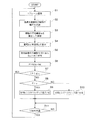
次に、制御部21の制御処理動作を図3のフローチャートを用いて説明する。
第1および第2撮像部12,17において各1フレームの撮像が終了すると(ステップS1)、まず、透過光画像中の細胞の輪郭を追跡する処理が行われ、細胞画像が切り出される(ステップS2)。切り出された細胞画像の平均輝度Iaが算出されて格納部26へ保存され(ステップS3)、細胞画像の面積Sと周囲長Lが算出される(ステップS4)。また、面積Sと周囲長Lから細胞の大きさ(円相当径)や細胞の丸さ(円形度)が算出される。
Next, the control processing operation of the
When each of the first and
次に、蛍光画像中の細胞画像が切り出され、上記S,Lと共に格納部26へ保存される(ステップS5)。また、面積Sと周囲長Lから細胞核の大きさ(円相当径)や細胞核の丸さ(円形度)が算出される。
次に、細胞の透過光画像の平均輝度Iaと所定値Isとを比較するために、P=K(Is−Ia)が演算される(ステップS6)。ここで、Kは定数である。
Next, the cell image in the fluorescence image is cut out and stored in the
Next, P = K (Is−Ia) is calculated in order to compare the average luminance Ia of the transmitted light image of the cell with the predetermined value Is (step S6). Here, K is a constant.
そして、Pが所定範囲ε内にあるか否か、つまり|P|≦εであるか否かが判別される(ステップS7)。|P|≦εであれば、ステップS1から1/30秒の時間が経過すると(ステップS11)、次のフレームの撮像が行われる。
ステップS7において|P|≦εでない場合で、P>εである場合には(ステップS8)、図1の駆動制御部27からステッピングモータ23に1ステップ分の正回転駆動パルスが出力され、フローセル1が対物レンズ6から遠ざかるように矢印A方向へ移動する。
また、ステップS8においてP>εでない場合、つまりP<−εである場合には、駆動制御部27からステッピングモータ23に1ステップ分の逆回転駆動パルスが出力され、フローセル1が対物レンズ6へ近づくように矢印B方向へ移動する。
Then, it is determined whether or not P is within a predetermined range ε, that is, whether or not | P | ≦ ε (step S7). If | P | ≦ ε, when the time of 1/30 seconds elapses from step S1 (step S11), the next frame is imaged.
When | P | ≦ ε is not satisfied in step S7, and P> ε (step S8), a forward rotation drive pulse for one step is output from the
If P> ε is not satisfied in step S8, that is, if P <−ε, the reverse rotation drive pulse for one step is output from the
このように、第1受光光学系の焦点を第1撮像部12の撮像面よりも遠い位置に合わすようにしたので、黒いベッケ線に包まれた透過光画像であるコントラストの大きい細胞画像が得られる。このコントラストの大きい細胞画像を用いることにより、細胞画像の輪郭抽出が容易となり、単純な画像処理で、細胞画像の大きさや丸さを高速に算出できる。
また、細胞の蛍光画像から得られる細胞核の大きさを用いることにより、抗がん剤などの薬剤による細胞核の大きさの変化をとらえ、薬剤の効果を確認できる。
この実施例では前述のように蛍光画像撮像系の焦点は試料流5の中心軸に合うように設定され、透過光撮像系の焦点は細胞の透過光画像が黒いベッケ線でつつまれるように蛍光画像撮像系の焦点よりも遠くに設定されている。しかし、試料流5の中を流れる細胞列が何らかの原因により試料流5の中心軸からずれると、透過光画像撮像系および蛍光画像撮像系の焦点に対する撮像対象の位置がずれるため、所望の画像がコントラスト良く得られない。
そこで、この発明では上記のように透過光画像の細胞の平均輝度(細胞画像の濃淡)から細胞列の位置ずれを検出し、それに対応してフローセル1を移動させ、撮像対象が常に正規の位置の方向へ補正されるようにしている。
このようにして、1サンプル分の撮像が終了すると、格納部26に格納されている各種データは必要に応じて表示部30に表示される。
As described above, since the focus of the first light receiving optical system is set to a position farther from the imaging surface of the
Further, by using the size of the cell nucleus obtained from the fluorescence image of the cell, the effect of the drug can be confirmed by capturing the change in the size of the cell nucleus caused by the drug such as an anticancer drug.
In this embodiment, as described above, the focal point of the fluorescent imaging system is set so as to be aligned with the central axis of the
Therefore, in the present invention, as described above, the displacement of the cell row is detected from the average luminance of the cells in the transmitted light image (the density of the cell image), and the
In this way, when imaging for one sample is completed, various data stored in the
第2実施例
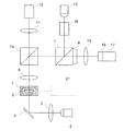
図4はこの発明の第2実施例を示す構成説明図である。同図において、第1実施例(図1)と同じ要素には同じ参照番号を付している。
図4において、透過画像の撮像系は、試料流5中の細胞を照明するための第1照明光学系と試料流5中の細胞からの光像を受光するための第1受光光学系(第1光学系)からなる。第1照明光学系は、第1光源2、コンデンサレンズ3および反射ミラー4から構成される。第1受光光学系(第1光学系)は、対物レンズ6、ダイクロイックミラー7a、結像レンズ11、および第1撮像部12から構成される。
一方、蛍光画像の撮像系は、試料流5の細胞を照明するための第2照明光学系と試料流5の細胞からの光像を受光するため第2受光光学系(第2光学系)からなる。第2照明光学系は、第2光源13、ビームイクスパンダ18、ダイクロイックミラー7、7a、および対物レンズ6から構成される。第2受光光学系(第2光学系)は、対物レンズ6、ダイクロイックミラー7a、7、蛍光フィルタ8、ハーフミラー9、結像レンズ15、ゲート付きイメージインテンシファイヤ16、および第2撮像部17から構成される。ここで、ダイクロイックミラー7aは、500nm以下の波長の光を反射し、500nmより大きい波長の光を透過させる。
Second Embodiment FIG. 4 is an explanatory diagram showing the construction of a second embodiment of the present invention. In the figure, the same reference numerals are assigned to the same elements as those in the first embodiment (FIG. 1).
In FIG. 4, the transmission image capturing system includes a first illumination optical system for illuminating cells in the
On the other hand, the imaging system of the fluorescence image includes a second illumination optical system for illuminating the cells of the
第1受光光学系の焦点は、第1撮像部12の撮像面よりも遠い位置に合わされ、黒いベッケ線に包まれた透過光画像が得られるように結像レンズ11と撮像部12の間の光路長が設定される。また、第2受光光学系の焦点は、第2撮像部17の撮像面に合うように結像レンズ15と第2撮像部17との光路長が設定され、コントラストの良い蛍光画像が得られる。ここで、対物レンズ6の焦点は、試料流5の中心軸に合うように設定されている。
The focal point of the first light receiving optical system is adjusted to a position farther than the imaging surface of the
このような構成における動作について次に説明する。
図2は、撮像制御部21から出力される信号、つまり第2光源13および第1光源2をそれぞれ点灯させるパルス信号S1,S3と、イメージインテンシファイヤ16のゲートを開くパルス信号S3のタイミングチャートである。
まず、フローセル1に試料流5が形成されると、制御部21から出力されるパルス信号S1によって第2光源13が365nmの波長の光を発光する。第2光源13の出射光はビームイクスパンダ18を通ってダイクロイックミラー7でダイクロイックミラー7aの方へ反射され、さらにダイクロイックミラー7aで反射されて対物レンズ6を介して試料流5内の細胞を落射照明する。それによって、細胞内の蛍光染色された核から400〜500nmの波長の蛍光が励起され、結像レンズ6,ダイクロイックミラー7a,ダイクロイックミラー7,蛍光フィルタ8,および結像レンズ15を介してイメージインテンシファイヤ16へ到達する。この時、イメージインテンシファイヤ16のゲートは、撮像制御部21から出力されるパルス信号S2により、図2に示すように開いているので、核の蛍光画像がイメージインテンシファイヤ16の光電面に結像し、増幅される。増幅された蛍光画像は第2撮像部17によって撮像され、蛍光画像データとして制御部21へ送られる。
Next, the operation in such a configuration will be described.
FIG. 2 is a timing chart of signals output from the
First, when the
図2に示すように、イメージインテンシファイヤ16のゲートを開くパルス信号S2がオフになり、そのゲートが閉じると、次に、制御部21からパルス信号S3が出力され、第1光源2が発光する。第1光源2の出射光はコンデンサレンズ3および反射ミラー4を介して試料流5内の細胞を照明する。そして、細胞を透過した透過光は、対物レンズ6,ダイクロイックミラー7a,および結像レンズ11を介して第1撮像部12へ入射する。それによって、細胞の透過光画像が第1撮像部12により撮像され、透過光画像データとして制御部21へ送られる。このような第1および第2撮像部12,17による各撮像動作が1秒間に30回くり返される。これによって、1秒間に各30フレームの透過光画像と蛍光画像が得られる。つまり、1秒間に30組の透過光画像と蛍光画像が得られる。
得られた蛍光画像データおよび透過光画像データは、第1実施例と同様に制御部21において、図3に示すように処理され、フローセル1の位置も同様に駆動制御される。
As shown in FIG. 2, when the pulse signal S2 for opening the gate of the
The obtained fluorescence image data and transmitted light image data are processed as shown in FIG. 3 by the
第3実施例
図5はこの発明の第3実施例を示す構成説明図である。同図において、第1実施例(図1)と同じ要素には同じ参照番号を付している。なお、第3実施例では、第1実施例における第1光源2が省略されている。
透過画像の撮像系は、試料流5中の細胞を照明するための第1照明光学系と試料流5中の細胞からの光像を受光するための第1受光光学系(第1光学系)からなる。第1照明光学系は、第2光源13、コンデンサレンズ14および反射ミラー4から構成される。第1受光光学系(第1光学系)は、対物レンズ6、ダイクロイックミラー7、蛍光フィルタ8、反射ミラー10、結像レンズ11、および第1撮像部12から構成される。
一方、蛍光画像の撮像系は、試料流5の細胞を照明するための第1照明光学系と試料流5の細胞からの光像を受光するため第2受光光学系(第2光学系)からなる。第1照明光学系は、第2光源13、コンデンサレンズ14および反射ミラー4から構成される。第2受光光学系(第2光学系)は、対物レンズ6、ダイクロイックミラー7、蛍光フィルタ8、結像レンズ15、ゲート付きイメージインテンシファイヤ16、および第2撮像部17から構成される。
Third Embodiment FIG. 5 is an explanatory diagram showing the configuration of a third embodiment of the present invention. In the figure, the same reference numerals are assigned to the same elements as those in the first embodiment (FIG. 1). In the third embodiment, the first
The transmission image imaging system includes a first illumination optical system for illuminating cells in the
On the other hand, the imaging system for the fluorescence image includes a first illumination optical system for illuminating the cells in the
第1受光光学系の焦点は、第1撮像部12の撮像面よりも遠い位置に合わされ、黒いベッケ線に包まれた透過光画像が得られるように結像レンズ11と撮像部12の間の光路長が設定される。また、第2受光光学系の焦点は、第2撮像部17の撮像面に合うように結像レンズ15と第2撮像部17との光路長が設定され、コントラストの良い蛍光画像が得られる。ここで、対物レンズ6の焦点は、試料流5の中心軸に合うように設定されている。
The focal point of the first light receiving optical system is adjusted to a position farther than the imaging surface of the
このような構成における動作について次に説明する。
まず、フローセル1に試料流5が形成されると、制御部21から出力されるパルス信号によって第2光源13が365nmの波長の光を発光する。第2光源13の出射光はコンデンサレンズ14を通って反射ミラー4で反射され、試料流5内の細胞を透過照明する。それによって、細胞内の蛍光染色された核から400〜500nmの波長の蛍光が励起され、励起された蛍光は、結像レンズ6,ダイクロイックミラー7,蛍光フィルタ8,および結像レンズ15を介してイメージインテンシファイヤ16へ到達する。この時、イメージインテンシファイヤ16のゲートは、制御部21から出力されるパルス信号により開かれて核の蛍光画像がイメージインテンシファイヤ16の光電面に結像し、増幅される。増幅された蛍光画像は第2撮像部17によって撮像され、蛍光画像データとして制御部21へ送られる。
Next, the operation in such a configuration will be described.
First, when the
一方、細胞を透過した透過光は、ダイクロイックミラー7によって反射され、反射ミラー10および結像レンズ11を介して第1撮像部12へ入射し、細胞の透過光画像が第1撮像部12により撮像され、透過光画像データとして制御部21へ送られる。このような第1および第2撮像部12,17による各撮像動作が1秒間に30回くり返される。これによって、1秒間に各30フレームの透過光画像と蛍光画像が得られる。つまり、1秒間に30組の透過光画像と蛍光画像が得られる。
得られた蛍光画像データおよび透過光画像データは、第1実施例と同様に制御部21において、図3に示すように処理され、フローセル1の位置も同様に駆動制御される。
On the other hand, the transmitted light that has passed through the cell is reflected by the
The obtained fluorescence image data and transmitted light image data are processed as shown in FIG. 3 by the
以上のように、第1〜3実施例では第1受光光学系(第1光学系)の焦点が第1撮像部12の撮像面より遠い位置になるように設定したが、本発明はこれに限定されない。例えば、第1受光光学系(第1光学系)の焦点は第1撮像部12の撮像面に設定し、対物レンズ6の焦点が、試料流5の中心軸よりも遠い位置になるように設定しても良い。この場合には、第2受光光学系は、第1受光光学系の対物レンズ6とは別の第2対物レンズを備える構成を有しており、この第2対物レンズの焦点は試料流5の中心軸にあることが好ましい。
As described above, in the first to third embodiments, the focal point of the first light receiving optical system (first optical system) is set to be far from the imaging surface of the
なお、本出願は産業再生法第30条の適用を受ける特許出願である。
This application is a patent application subject to
1 フローセル
2 第1光源
3 コンデンサレンズ
4 反射ミラー
5 試料流
6 対物レンズ
7 ダイクロイックミラー
8 蛍光フィルタ
9 ハーフミラー
10 反射ミラー
11 結像レンズ
12 第1撮像部
13 第2光源
14 コンデンサレンズ
15 結像レンズ
16 ゲート付きイメージインテンシファイヤ
17 第2撮像部
18 ビームイクスパンダ
21 制御部
22 直線移動機構
23 ステッピングモータ
24 信号処理部
25 演算部
26 格納部
27 駆動制御部
28 撮像制御部
29 変位部
30 表示部
DESCRIPTION OF
Claims (11)
Priority Applications (1)
| Application Number | Priority Date | Filing Date | Title |
|---|---|---|---|
| JP2004105332A JP2005291831A (en) | 2004-03-31 | 2004-03-31 | Imaging flow site meter |
Applications Claiming Priority (1)
| Application Number | Priority Date | Filing Date | Title |
|---|---|---|---|
| JP2004105332A JP2005291831A (en) | 2004-03-31 | 2004-03-31 | Imaging flow site meter |
Related Child Applications (1)
| Application Number | Title | Priority Date | Filing Date |
|---|---|---|---|
| JP2009210036A Division JP2009300454A (en) | 2009-09-11 | 2009-09-11 | Imaging flow site meter |
Publications (1)
| Publication Number | Publication Date |
|---|---|
| JP2005291831A true JP2005291831A (en) | 2005-10-20 |
Family
ID=35324932
Family Applications (1)
| Application Number | Title | Priority Date | Filing Date |
|---|---|---|---|
| JP2004105332A Pending JP2005291831A (en) | 2004-03-31 | 2004-03-31 | Imaging flow site meter |
Country Status (1)
| Country | Link |
|---|---|
| JP (1) | JP2005291831A (en) |
Cited By (10)
| Publication number | Priority date | Publication date | Assignee | Title |
|---|---|---|---|---|
| JP2009300454A (en) * | 2009-09-11 | 2009-12-24 | Sysmex Corp | Imaging flow site meter |
| JP2012521540A (en) * | 2009-03-20 | 2012-09-13 | バイオ−ラド ラボラトリーズ インコーポレイテッド | Sequential line scan encoded multicolor fluorescence microscopy and image flow cytometry |
| CN104502255A (en) * | 2014-12-29 | 2015-04-08 | 中国科学院长春光学精密机械与物理研究所 | Three-dimensional imaging flow cytometer device |
| JP2016524703A (en) * | 2013-05-15 | 2016-08-18 | キャピトル エルエルシー | Scanning image flow cytometer |
| JP2017142118A (en) * | 2016-02-09 | 2017-08-17 | 株式会社イシダ | Optical inspection device |
| US10036698B2 (en) | 2015-06-19 | 2018-07-31 | Captl Llc | Time-sequential cytometry |
| KR20200027674A (en) * | 2018-09-05 | 2020-03-13 | 주식회사 마하테크 | minute plastic detection apparatus |
| CN111307733A (en) * | 2018-11-27 | 2020-06-19 | 株式会社岛津制作所 | Atomic absorption spectrophotometer |
| US10900885B2 (en) | 2014-12-19 | 2021-01-26 | Captl Llc | Flow cytometry using hydrodynamically planar flow |
| KR20230157714A (en) * | 2022-05-10 | 2023-11-17 | 한국생산기술연구원 | Nanoplastic detection system and nanoplastic detection method |
-
2004
- 2004-03-31 JP JP2004105332A patent/JP2005291831A/en active Pending
Cited By (15)
| Publication number | Priority date | Publication date | Assignee | Title |
|---|---|---|---|---|
| JP2012521540A (en) * | 2009-03-20 | 2012-09-13 | バイオ−ラド ラボラトリーズ インコーポレイテッド | Sequential line scan encoded multicolor fluorescence microscopy and image flow cytometry |
| US9091654B2 (en) | 2009-03-20 | 2015-07-28 | Bio-Rad Laboratories, Inc. | Serial-line-scan-encoded multi-color fluorescence microscopy and imaging flow cytometry |
| JP2009300454A (en) * | 2009-09-11 | 2009-12-24 | Sysmex Corp | Imaging flow site meter |
| JP2016524703A (en) * | 2013-05-15 | 2016-08-18 | キャピトル エルエルシー | Scanning image flow cytometer |
| US10900885B2 (en) | 2014-12-19 | 2021-01-26 | Captl Llc | Flow cytometry using hydrodynamically planar flow |
| CN104502255A (en) * | 2014-12-29 | 2015-04-08 | 中国科学院长春光学精密机械与物理研究所 | Three-dimensional imaging flow cytometer device |
| US10036698B2 (en) | 2015-06-19 | 2018-07-31 | Captl Llc | Time-sequential cytometry |
| US10775292B2 (en) | 2015-06-19 | 2020-09-15 | Captl Llc | Multiple-spot time-sequential cytometry |
| JP2017142118A (en) * | 2016-02-09 | 2017-08-17 | 株式会社イシダ | Optical inspection device |
| KR20200027674A (en) * | 2018-09-05 | 2020-03-13 | 주식회사 마하테크 | minute plastic detection apparatus |
| KR102094373B1 (en) * | 2018-09-05 | 2020-03-27 | 주식회사 마하테크 | minute plastic detection apparatus |
| CN111307733A (en) * | 2018-11-27 | 2020-06-19 | 株式会社岛津制作所 | Atomic absorption spectrophotometer |
| CN111307733B (en) * | 2018-11-27 | 2023-06-09 | 株式会社岛津制作所 | Atomic Absorption Spectrophotometer |
| KR20230157714A (en) * | 2022-05-10 | 2023-11-17 | 한국생산기술연구원 | Nanoplastic detection system and nanoplastic detection method |
| KR102685059B1 (en) | 2022-05-10 | 2024-07-15 | 한국생산기술연구원 | Nanoplastic detection system and nanoplastic detection method |
Similar Documents
| Publication | Publication Date | Title |
|---|---|---|
| JP4288323B1 (en) | Microscope device and fluorescence observation method using the same | |
| US11042016B2 (en) | Multi-Z confocal imaging system | |
| US8077200B2 (en) | Image capture system and method of capturing labeled image | |
| JP2014528060A (en) | Optical biosensor with multiple sensor areas | |
| US20110211067A1 (en) | Sample analysis apparatus and a method of analysing a sample | |
| US12019005B2 (en) | Cell observation system and cell observation method | |
| JP2006030992A (en) | Apparatus for microscopic observation and / or microscopic detection and use thereof | |
| JP2005291831A (en) | Imaging flow site meter | |
| JP6423841B2 (en) | Sample observation apparatus and sample observation method | |
| JP2013535687A (en) | Cytometry system with a solid numerical aperture increasing lens | |
| US20140218794A1 (en) | Confocal Fluorescence Microscope | |
| JP4854880B2 (en) | Laser microscope | |
| JP4474655B2 (en) | Microscope equipment | |
| EP1494226A3 (en) | Objective lens optical pickup and optical information processing apparatus using the same | |
| JP2001083088A (en) | Quantum dot observation method and device | |
| US11500188B2 (en) | Microscope with focusing system | |
| JP2002202459A (en) | Dark visual field vertical illumination microscope | |
| CN115508994A (en) | Microscopic imaging system | |
| JP2009300454A (en) | Imaging flow site meter | |
| JPH07270302A (en) | Imaging flow sight meter | |
| JPH10123425A (en) | Fluorescence microscope with zoom function | |
| JP5307868B2 (en) | Total reflection microscope | |
| JPH07134242A (en) | Focus detector | |
| EP1762874A3 (en) | Lens apparatus comprising a focus-state detecting unit | |
| JP7770682B2 (en) | 3D image capturing device |
Legal Events
| Date | Code | Title | Description |
|---|---|---|---|
| A621 | Written request for application examination |
Free format text: JAPANESE INTERMEDIATE CODE: A621 Effective date: 20070226 |
|
| A977 | Report on retrieval |
Free format text: JAPANESE INTERMEDIATE CODE: A971007 Effective date: 20080619 |
|
| A131 | Notification of reasons for refusal |
Free format text: JAPANESE INTERMEDIATE CODE: A131 Effective date: 20081007 |
|
| A521 | Request for written amendment filed |
Free format text: JAPANESE INTERMEDIATE CODE: A523 Effective date: 20081126 |
|
| A02 | Decision of refusal |
Free format text: JAPANESE INTERMEDIATE CODE: A02 Effective date: 20090616 |
|
| A521 | Request for written amendment filed |
Free format text: JAPANESE INTERMEDIATE CODE: A523 Effective date: 20090911 |