JP2005291842A - Irradiation device - Google Patents
Irradiation device Download PDFInfo
- Publication number
- JP2005291842A JP2005291842A JP2004105448A JP2004105448A JP2005291842A JP 2005291842 A JP2005291842 A JP 2005291842A JP 2004105448 A JP2004105448 A JP 2004105448A JP 2004105448 A JP2004105448 A JP 2004105448A JP 2005291842 A JP2005291842 A JP 2005291842A
- Authority
- JP
- Japan
- Prior art keywords
- light
- irradiation device
- irradiation
- annular
- dark
- Prior art date
- Legal status (The legal status is an assumption and is not a legal conclusion. Google has not performed a legal analysis and makes no representation as to the accuracy of the status listed.)
- Pending
Links
- 230000001678 irradiating effect Effects 0.000 claims abstract 2
- 230000007547 defect Effects 0.000 claims description 26
- 239000003973 paint Substances 0.000 claims description 5
- 239000011248 coating agent Substances 0.000 abstract description 31
- 238000000576 coating method Methods 0.000 abstract description 31
- 230000002093 peripheral effect Effects 0.000 abstract description 3
- 238000007689 inspection Methods 0.000 description 30
- 238000010422 painting Methods 0.000 description 5
- 229920003002 synthetic resin Polymers 0.000 description 5
- 239000000057 synthetic resin Substances 0.000 description 5
- 239000000463 material Substances 0.000 description 3
- 238000000034 method Methods 0.000 description 3
- 239000000758 substrate Substances 0.000 description 3
- 239000000725 suspension Substances 0.000 description 3
- 125000002066 L-histidyl group Chemical group [H]N1C([H])=NC(C([H])([H])[C@](C(=O)[*])([H])N([H])[H])=C1[H] 0.000 description 1
- 230000005540 biological transmission Effects 0.000 description 1
- 239000003086 colorant Substances 0.000 description 1
- 230000003247 decreasing effect Effects 0.000 description 1
- 239000000428 dust Substances 0.000 description 1
- 230000003760 hair shine Effects 0.000 description 1
- 239000003550 marker Substances 0.000 description 1
- 239000002184 metal Substances 0.000 description 1
- 230000000007 visual effect Effects 0.000 description 1
- 210000000707 wrist Anatomy 0.000 description 1
Images

Landscapes
- Investigating Materials By The Use Of Optical Means Adapted For Particular Applications (AREA)
- Coating Apparatus (AREA)
Abstract
Description
本発明は、塗装面に対向配置可能な明暗パターンを備えた塗装面検査用の照射装置に関する。 The present invention relates to an irradiation apparatus for a painted surface inspection having a light and dark pattern that can be disposed opposite to a painted surface.
この種の照射装置としては、本発明に関連する先行技術文献情報として下記に示す特許文献1に記されたものがある。この特許文献1の発明は、自動車ボディの塗装ラインの最終工程である塗完検査ラインにおいてゴミ、ブツなどの塗装欠陥を検出するための装置と方法に関しており、前記装置は、コンベアにより移動する自動車ボディの両側面に立てられた透過スクリーンと、透過スクリーンに所定のストライプパターンを投影する投影機とを備えており、透過スクリーンに投影されたストライプパターンが透過スクリーンを透過して、自動車ボディの塗装面に映るように構成されている。ストライプパターンは明暗コントラストを有する縦の縞模様からなり、例えば自動車ボディの塗装面に投影された暗い部分に塗装欠陥があると、その部分のみが光って観察されるので、作業者は目視によって塗装欠陥を検出することができるようになっている。すなわち、ここでは照射装置は透過スクリーンと投影機とで構成されており、照射装置が有する明暗パターンは縦のストライプ状となっている。
しかし、特許文献1の照射装置では、塗装欠陥のサイズが或る寸法を下回ると検出するのが困難になるという問題があった。
However, the irradiation apparatus of
したがって、本発明の目的は、より寸法の小さな塗装欠陥でも検出し易い照射装置を提供することにある。 Accordingly, an object of the present invention is to provide an irradiation apparatus that can easily detect even a coating defect having a smaller size.
本発明の第1の特徴構成は、塗装面に対向配置可能な明暗パターンを備えた塗装面検査用の照射装置であって、
前記明暗パターンは、塗装面の微小欠陥を全周方向から照射可能な環状の明部を有し、前記環状の明部はバックグラウンド状の暗部内に網目状に延びている点にある。
したがって、本発明の第1の特徴構成による照射装置では、明暗パターンの一方を形成する明部が、微小欠陥を全周方向から包囲可能な環状を呈しているので、非常に小さな寸法の塗装欠陥や傷でも、塗装面に形成された暗部の中に、塗装欠陥や傷が明部からの光を乱反射することによる光輝部が明白に浮かび上がり、より確実な塗装欠陥や傷の検出が可能となる。さらに、本発明の第1の特徴構成による照射装置では、複数の環状の明部がバックグラウンド状の暗部内に網目状に連続して延びているので、作業者はこのように網目状に延びた複数の環状の明部で覆われた比較的に広い領域を一度に観察することができ、より高い検査能率が得られる。尚、本発明の第1の特徴構成による照射装置によって、非常に小さな寸法の塗装欠陥や傷でも検出可能となったという知見から、従来の明暗パターンが縦のストライプ状となっている照射装置において、小さな寸法の塗装欠陥を検出し難かった原因は、塗装欠陥がその左右に位置する明部によってのみ照射されたためであろうと推察することができる。
A first characteristic configuration of the present invention is an irradiation apparatus for coating surface inspection having a light and dark pattern that can be disposed opposite to a coating surface,
The bright and dark pattern has an annular bright portion that can irradiate minute defects on the coating surface from the entire circumference, and the annular bright portion extends in a mesh shape in the background dark portion.
Therefore, in the irradiation apparatus according to the first characteristic configuration of the present invention, the bright part forming one of the bright and dark patterns has an annular shape that can surround the minute defect from the entire circumferential direction. Even in the case of scratches and scratches, the bright areas due to the coating defects and scratches reflecting the light from the bright areas clearly appear in the dark areas formed on the painted surface, making it possible to detect coating defects and scratches more reliably. Become. Furthermore, in the irradiation device according to the first characteristic configuration of the present invention, the plurality of annular bright portions continuously extend in a mesh shape in the background dark portion, and thus the operator extends in this manner. In addition, a relatively wide area covered with a plurality of annular bright portions can be observed at a time, and higher inspection efficiency can be obtained. In addition, from the knowledge that the irradiation apparatus according to the first characteristic configuration of the present invention can detect even coating defects and scratches of very small dimensions, in the irradiation apparatus in which the conventional light and dark pattern is a vertical stripe shape. It can be inferred that the reason why it was difficult to detect the coating defect having a small size was that the coating defect was irradiated only by the bright portions located on the left and right sides thereof.
より具体的には、前記環状の明部を、互いに隣接配置された多数のLED光源によって構成することができる。
このように構成すれば、基板などに多数のLED光源を、所定の環状のパターンが得られるように配置して固定するという簡単な手法で照明装置を作製することができる。また、個々のLED光源は比較的自由に配置できるので、複数のLED光源によって形成される形状も自由に選択可能となる。また、発熱量の小さな光源としてのLEDを用いることで、省エネルギーに寄与すると同時に、明部に隣接したバックグラウンド状の暗部を形成するための素材を、余り耐熱性の高くない合成樹脂を含む広範な材料から選択することが可能となる。
More specifically, the annular light portion can be constituted by a large number of LED light sources arranged adjacent to each other.
If comprised in this way, an illuminating device can be produced with the simple method of arrange | positioning and fixing many LED light sources on a board | substrate etc. so that a predetermined | prescribed annular pattern may be obtained. Moreover, since each LED light source can be arrange | positioned comparatively freely, the shape formed with a some LED light source can also be selected freely. In addition, by using an LED as a light source with a small calorific value, it contributes to energy saving, and at the same time, a material for forming a background-like dark part adjacent to a bright part is a wide range including a synthetic resin that is not very heat resistant. It is possible to select from various materials.
特に、前記環状の明部は正六角形の環を一単位とするハニカム状を呈する構成とすることができる。
このように構成すれば、互いに形状が正六角形と等しく、寸法も互いに等しい多数の環状の明部のみで明暗パターンを埋め尽くすことができるので、明暗パターンが非常に規則正しいものとなり、塗装欠陥や傷をより検出し易くなる。
In particular, the annular light portion may have a honeycomb shape having a regular hexagonal ring as a unit.
If configured in this way, the light and dark pattern can be filled with only a large number of annular bright parts having the same shape as the regular hexagon and the same size as each other. Can be detected more easily.
作業者が手動で上下及び横方向に移動操作自在なハンディ型の照射装置である構成とすることができる。
このように構成すれば、作業者は、照射装置を自動車ボディの塗装面に沿って自在に移動させながら塗装面を観察することで、自動車ボディの全面にわたって塗装欠陥や傷が無いか容易に検査することができる。また、このように構成すれば、作業者は、照射装置から自動車ボディの塗装面までの距離を自由に変更することができるので、自動車ボディの塗装色の如何に関わらず、塗装欠陥や傷が最も検出され易い条件で検査を実施することができる。同様に、照射装置が自動車ボディの塗装面に対してなす角度を自動車ボディの輪郭形状などに合わせて適宜変更することができるので、自動車ボディの輪郭形状に関わらず、塗装欠陥や傷が最も検出され易い条件で検査を実施することができる。
It can be set as the structure which is a handy type irradiation apparatus which an operator can move and operate manually up and down and laterally.
With this configuration, the operator can easily inspect the entire surface of the automobile body for coating defects and scratches by observing the painted surface while freely moving the irradiation device along the painted surface of the automobile body. can do. Also, with this configuration, the operator can freely change the distance from the irradiation device to the painted surface of the automobile body, so that there are no coating defects or scratches regardless of the painted color of the automobile body. The inspection can be performed under conditions that are most easily detected. Similarly, the angle formed by the irradiation device with respect to the painted surface of the car body can be changed as appropriate according to the car body contour shape, etc., so that most coating defects and scratches are detected regardless of the car body contour shape. Inspection can be carried out under conditions that are easily performed.
本発明によるその他の特徴および利点は、以下図面を用いた実施形態の説明により明らかになるであろう。 Other features and advantages of the present invention will become apparent from the following description of embodiments using the drawings.
本発明による照射装置の実施形態について図面を参照しながら以下に解説する。
図1は、本発明の一実施形態としての照射装置を備えた自動車用の塗完検査区域1を上方から見た状態を示す。
塗完検査区域1は、塗装ラインの最終段に設けられており、前段での塗装を終えた自動車ボディBを一定の遅い速度で搬送するコンベア2を有する。また、コンベア2によって搬送されて来る自動車ボディBの両側には、塗完検査区域1内に余分な外光が進入するのを防止するための板状または膜状の遮光手段3が設置されている。塗完検査区域1には、通常2名の検査作業員Pが配置されており、自動車ボディBの両側に位置している。
各検査作業員Pは、片手にハンディ型の照射装置4を携えており、照射装置4から発される光によって自動車ボディBの塗装面を照らしながら、自動車ボディBのほぼ全面にわたって塗装面を観察し、塗装面の上に塗装欠陥や傷を検出すればこれをマーカーなどでマーキングする。
Embodiments of an irradiation apparatus according to the present invention will be described below with reference to the drawings.
FIG. 1 shows a state in which a coating
The coating
Each inspection worker P carries a
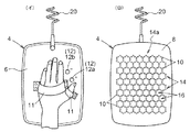
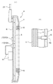
図2に示すように、照射装置4は、金属または合成樹脂などからなる背面パネル6と、背面パネル6の周縁部に固定された照射パネル8とを有する。図3に示すように、照射パネル8は、背面パネル6との間に所定の厚さの空間を形成するように、湾曲した周部を備え、照射パネル8と背面パネル6との間に形成された空間には基板9が配置されている。照射パネル8は、黒色で不透明の合成樹脂などで形成されており、その中央部には多数の貫通孔8aが形成されている。貫通孔8aは、正六角形の環を一単位とするハニカム状を呈するように規則的に配置されている。個々の貫通孔8aには、所定の発光色を持つLED10の先端が挿通されている。LED10はリード部を介して基板9に固定されている。
As shown in FIG. 2, the
背面パネル6には検査作業員Pが一方の手を差し込むことのできるベルト11が設けられており、検査作業員Pがこのベルト11を介して照射装置4を手に取り付ければ、腕や手首の角度を調節するだけで、照射装置4を上下及び横方向に移動操作することができ、照射パネル8から塗装面までの距離や照射パネル8の塗装面に対する角度を自由に変えられる。尚、背面パネル6には、照射装置4を塗完検査区域1の天井などから、上下方向および東西南北方向に移動自在に懸架する吊り下げ用索20が連結されている。吊り下げ用索20は、照射装置4の重量による検査作業員Pの疲労を軽減する。また、吊り下げ用索20は、照射装置4に対して給電するための導線(不図示)を保護する機能も果たしている。
The
また、背面パネル6には、検査作業員PがLED10の光量を、検査対象となる自動車ボディの塗装色や塗完検査区域1内の明暗度に応じて、或いは、検査作業員Pの視力特性などに応じて調節するための光量調節ボタン12(操作手段の一例)が設けられている。光量調節ボタン12は、検査作業員Pが照射装置4を手に取り付けたままで、その取り付けている側の手の指操作によって光量調節ボタン12を操作可能に設けられている。全てのLED10が互いに等しい光量で発光するように構成されており、光量調節ボタン12を1秒以下の時間長さで操作すれば照射パネル8に並ぶ全てのLED10の光量が同時に増減される。光量調節ボタン12はLED10の光量を標準レベルより高めるプラスボタン12aと標準レベルより下げるマイナスボタン12bとからなる。プラスボタン12aは、照射装置4の電源入り切り機能を兼ね備えており、電源OFF状態の時にプラスボタン12aを3秒間以上押し続ければ、電源入り状態となってLED10が標準の光量レベルで点灯され、電源ON状態の時にプラスボタン12aを3秒間以上押し続ければ、電源切り状態となってLED10への通電が停止される。
Further, the inspection worker P determines the light intensity of the
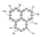
照射装置4のLED10を点灯させると、照射パネル8には個々のLED10が形成する明部と、LED10に隣接した黒色で不透明な合成樹脂が作る暗部とからなる明暗パターンが形成される。具体的には、図4に示すように、12個のLED10によって正六角形(環状の一例)の単位明部14aが作られ、さらに多数の前記正六角形が連続的に接続されることで、全体としてハニカム状(網目状の一例)の明部14が、バックグラウンド状の暗部16内に延びた形態を取る。暗部16は、照射パネル8の黒色で不透明な合成樹脂によって形成されている。
When the
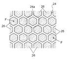
そして、検査作業員Pが照射パネル8を自動車ボディBの塗装面に対向させた状態で塗装面を観察すると、図5に示すように、検査作業員Pの目には、LED10から発される光によって形成されたハニカム状の明るい帯24が塗装面に映っているのが見える。ハニカムの個々の六角形のセル24a、すなわちハニカムの一単位は、正六角形状に並んだ12個のLED10からの光が塗装面に映ることで作られている。ハニカム状の明るい帯24或いは六角形の光のセル24aが、暗いバックグラウンド26内に浮かび上がって見える。検査中、検査作業員Pは塗装面に目の焦点を合わせても良いが、塗装面に映っている幾つかのLED10(例えば互いに隣接した5〜6個の単位明部14aを構成するLED10)自体に目の焦点を合わせても良い。照射装置4を塗装面に沿って移動させながら塗装面の観察を行うと、塗装面に欠陥Fが存在する場合には、欠陥Fが正六角形のセル24aの内部に入った時、欠陥Fは、欠陥Fを取り巻く12個のLED10によって全周方向から照射されるため、本来は全体が暗い筈のバックグラウンド26内に欠陥Fのみが孤立してくっきりと輝くので、欠陥Fが非常に微細であっても検査作業員Pの目によって明確に捉えられる。尚、図5では、簡単のために、六角形のセル24aを構成する各辺は同じ幅を持った直線で示されているが、輪郭が円形の3つの光のスポットが直線状に並んだように見える場合もある。
Then, when the inspection worker P observes the painted surface with the
〔別実施形態〕
<1>照射パネル8にて発光させるLED10として、RGBの各発光色に対応した3つのLEDチップを備えたハイブリッド型の白色LEDを用い、照射装置4の背面パネル6などに別途設けた操作ボタン(不図示)によってLED10からの発光色を、検査対象となる自動車ボディの塗装色に応じて変更可能な構成としても良い。
[Another embodiment]
<1> An operation button provided separately on the
<2>LED10を照射パネル8に環状に並べるのではなく、不透光性の材料からなる照射パネル8に環状のスリット、或いは、環状に並んだ多数の貫通孔を形成し、照射パネル8の内側に蛍光灯その他の発光部材を取り付けることで、環状のスリットから光が漏れ出るようにし、スリットによって形成される明部とスリット以外の部位によって形成される暗部とから明暗パターンを形成するように構成しても良い。
<2> Instead of arranging the
<3>照射装置4を検査作業員が手に携えて用いるハンディ型の照射装置4として用いるのではなく、塗完検査区域1の床上などに立てたスタンドなどに固定しておき、照射装置4によって照射される塗装面を検査作業員が目視で検査する構成を取っても良い。この場合、さらに、照射装置4によって照射される塗装面の画像をTVカメラなどによって読み取り、読み取られた画像をコンピュータによって解析することで、塗装面の欠陥や傷を検出したり、欠陥や傷の位置を特定する構成を取っても良い。
<3> The
1 塗完検査区域
2 コンベア
3 遮光手段
4 照射装置
10 LED
12 光量調節ボタン
14 ハニカム状の明部(明暗パターン)
14a 単位明部(明暗パターン、環状の明部)
16 暗部(明暗パターン)
24 ハニカム状の明るい帯
26 バックグラウンド
B 自動車ボディ
F 欠陥
1 Coating completion inspection area 2 Conveyor 3 Shading means 4
12 Light
14a Unit bright part (bright / dark pattern, annular bright part)
16 Dark part (light / dark pattern)
24
Claims (4)
前記明暗パターンは、塗装面の微小欠陥を全周方向から照射可能な環状の明部を有し、前記環状の明部はバックグラウンド状の暗部内に網目状に延びている照射装置。 An irradiation device for inspecting the paint surface with a light and dark pattern that can be placed opposite the paint surface,
The light / dark pattern has an annular bright part capable of irradiating minute defects on a painted surface from the entire circumference, and the annular bright part extends in a mesh shape in a background dark part.
Priority Applications (1)
| Application Number | Priority Date | Filing Date | Title |
|---|---|---|---|
| JP2004105448A JP2005291842A (en) | 2004-03-31 | 2004-03-31 | Irradiation device |
Applications Claiming Priority (1)
| Application Number | Priority Date | Filing Date | Title |
|---|---|---|---|
| JP2004105448A JP2005291842A (en) | 2004-03-31 | 2004-03-31 | Irradiation device |
Publications (1)
| Publication Number | Publication Date |
|---|---|
| JP2005291842A true JP2005291842A (en) | 2005-10-20 |
Family
ID=35324942
Family Applications (1)
| Application Number | Title | Priority Date | Filing Date |
|---|---|---|---|
| JP2004105448A Pending JP2005291842A (en) | 2004-03-31 | 2004-03-31 | Irradiation device |
Country Status (1)
| Country | Link |
|---|---|
| JP (1) | JP2005291842A (en) |
Cited By (4)
| Publication number | Priority date | Publication date | Assignee | Title |
|---|---|---|---|---|
| EP1843145A1 (en) | 2006-04-03 | 2007-10-10 | Chuo Electronic Measurement Co., Ltd | Illuminating method in paint defect detecting machine |
| JP2012078197A (en) * | 2010-10-01 | 2012-04-19 | Toyota Motor Kyushu Inc | Painted surface inspection device of painted object and painted surface inspection method of painted object |
| JP2016142525A (en) * | 2015-01-29 | 2016-08-08 | 京セラ株式会社 | Light source for painted surface inspection, and luminaire for painted surface inspection |
| JP2022529924A (en) * | 2019-04-15 | 2022-06-27 | イリノイ トゥール ワークス インコーポレイティド | A system that visually scans articles during non-destructive (NDT) inspection |
-
2004
- 2004-03-31 JP JP2004105448A patent/JP2005291842A/en active Pending
Cited By (4)
| Publication number | Priority date | Publication date | Assignee | Title |
|---|---|---|---|---|
| EP1843145A1 (en) | 2006-04-03 | 2007-10-10 | Chuo Electronic Measurement Co., Ltd | Illuminating method in paint defect detecting machine |
| JP2012078197A (en) * | 2010-10-01 | 2012-04-19 | Toyota Motor Kyushu Inc | Painted surface inspection device of painted object and painted surface inspection method of painted object |
| JP2016142525A (en) * | 2015-01-29 | 2016-08-08 | 京セラ株式会社 | Light source for painted surface inspection, and luminaire for painted surface inspection |
| JP2022529924A (en) * | 2019-04-15 | 2022-06-27 | イリノイ トゥール ワークス インコーポレイティド | A system that visually scans articles during non-destructive (NDT) inspection |
Similar Documents
| Publication | Publication Date | Title |
|---|---|---|
| CN204629260U (en) | A kind of light source for crown cap defect intelligent detection equipment | |
| JPH08184567A (en) | Device and method for inspecting mirror reflection surface or half-mirror reflection surface | |
| KR101318483B1 (en) | Inspection system and method for identifying surface and body defects in a glass sheet | |
| US8598557B2 (en) | Method and apparatus for providing patterned illumination fields for machine vision systems | |
| JP2008202949A (en) | Defect inspection method and defect inspection apparatus | |
| CN105445194A (en) | Light source device used for forming regular patterns and aimed at highly reflective object | |
| JP2009174857A (en) | Illumination device and defect inspection apparatus using the same | |
| JP4949051B2 (en) | Vehicle lighting device | |
| JP4078050B2 (en) | LED lighting device | |
| JP2005291842A (en) | Irradiation device | |
| CN215953384U (en) | Workpiece inner hole detection device | |
| TWI470208B (en) | Vision illumination apparatus for semi-translucent device | |
| JP6554235B2 (en) | Defect point detection instrument | |
| CN117214187B (en) | Detection method and detection device | |
| JP2020153967A (en) | Methods and devices for inspecting the surface of moving sheets | |
| JP6955368B2 (en) | Attachment for lighting equipment | |
| CN206555823U (en) | Lamp box for pcb board automatic detection device | |
| CN214256439U (en) | Image sensor with a plurality of pixels | |
| JP6779344B2 (en) | Defective location detection device and defective location detection method | |
| CN212112514U (en) | Bright field and dark field directional reflection light source assembly based on combined light source | |
| KR100973303B1 (en) | Automobile exterior surface inspection lamp | |
| JP2005331302A (en) | Outside surface inspection method and outside surface inspection device | |
| KR100704505B1 (en) | Lighting device for creating indoor atmosphere of vehicle | |
| TWI822525B (en) | Lighting device | |
| CN119222536A (en) | Vehicle maintenance shed |