JP2005291950A - X-ray inspection equipment - Google Patents
X-ray inspection equipment Download PDFInfo
- Publication number
- JP2005291950A JP2005291950A JP2004108128A JP2004108128A JP2005291950A JP 2005291950 A JP2005291950 A JP 2005291950A JP 2004108128 A JP2004108128 A JP 2004108128A JP 2004108128 A JP2004108128 A JP 2004108128A JP 2005291950 A JP2005291950 A JP 2005291950A
- Authority
- JP
- Japan
- Prior art keywords
- ray
- image
- receiving element
- subject
- fluoroscopic
- Prior art date
- Legal status (The legal status is an assumption and is not a legal conclusion. Google has not performed a legal analysis and makes no representation as to the accuracy of the status listed.)
- Pending
Links
Images
Landscapes
- Analysing Materials By The Use Of Radiation (AREA)
- Length-Measuring Devices Using Wave Or Particle Radiation (AREA)
Abstract
【課題】構成を簡略化しつつ充分な拡大率を確保できるとともに、直視透視画像を確実に得ることが可能なX線検査装置を提供する。
【解決手段】ターゲット面TPの中心位置Cを焦点FとしてX線発生器1から照射したX線によりX線受像素子3で受像したX線透視画像G1に基づいて画像処理ユニット4で直視透視画像GDを出力できることで、直視透視画像GDを確実に得ることができる。ターゲット面TP上の各位置R,Lをそれぞれ焦点FとしてX線発生器1から照射したX線によりX線受像素子3で受像した各透視画像GR,GLに基づいて立体透視画像GSを画像処理ユニット4で出力できることで、X線発生器1を傾斜させる傾斜機構を設ける場合と比較して、全体の構成を簡略化しつつ充分な撮像拡大率Mを確保できる。
【選択図】図1An X-ray inspection apparatus capable of ensuring a sufficient magnification while simplifying the configuration and capable of reliably obtaining a direct-view fluoroscopic image.
An image processing unit 4 performs direct fluoroscopy based on an X-ray fluoroscopic image G1 received by an X-ray image receiving element 3 by X-rays irradiated from an X-ray generator 1 with a center position C of a target surface TP as a focal point F. Since the image GD can be output, the direct-view fluoroscopic image GD can be reliably obtained. A three-dimensional perspective image GS is obtained based on the respective perspective images GR and GL received by the X-ray image receiving element 3 by X-rays irradiated from the X-ray generator 1 with the respective positions R and L on the target surface TP as the focal point F. By being able to output by the processing unit 4, it is possible to secure a sufficient imaging magnification M while simplifying the overall configuration as compared with the case of providing a tilt mechanism that tilts the X-ray generator 1.
[Selection] Figure 1
Description
本発明は、立体的に透視可能な立体透視画像を出力可能なX線検査装置に関する。 The present invention relates to an X-ray inspection apparatus capable of outputting a stereoscopically visible stereoscopic image.
従来、被検体の内部の立体的な情報を認識するX線検査装置は、固定台に固定された被検体にX線を照射するX線発生器と、このX線発生器により照射されたX線によるX線透視画像を受像するX線受像素子と、X線発生器とX線受像素子、あるいは被検体とをそれぞれ同期させて傾斜させる傾斜機構とをそれぞれ備えている。そして、この傾斜機構により、X線発生器などを傾斜させることで、被検体を傾斜方向から透視し、この被検体の内部の立体的な構成を立体透視画像として認識可能となっているとともに、X線発生器などの傾斜角度を変化させている(例えば、特許文献1参照。)。 2. Description of the Related Art Conventionally, an X-ray inspection apparatus that recognizes three-dimensional information inside a subject includes an X-ray generator that irradiates the subject fixed on a fixed base, and an X-ray emitted by the X-ray generator. An X-ray receiving element that receives an X-ray fluoroscopic image by a line, and a tilting mechanism that tilts the X-ray generator and the X-ray receiving element or the subject in synchronization with each other. And, by tilting the X-ray generator or the like by this tilt mechanism, the subject can be seen through from the tilt direction, and the three-dimensional configuration inside the subject can be recognized as a three-dimensional perspective image, The inclination angle of the X-ray generator or the like is changed (for example, see Patent Document 1).
また、被検体の中心線に対して互いに線対称な左右両側にX線発生器を配置し、各X線発生器から被検体へと傾斜状にX線を照射する、いわゆるステレオビームにより得られた左右一対のX線透視画像を処理して立体透視画像を得るX線検査装置も知られている(例えば、特許文献2参照。)。
しかしながら、上述の特許文献1に記載されたX線検査装置では、傾斜機構によりX線発生器などを傾斜させるので、このX線発生器と、被検体、あるいは固定台との干渉を防止するためにX線発生器から被検体へと照射されるX線の傾斜角度が制限され、充分な拡大率を確保することが容易でないという問題点を有している。
However, in the X-ray inspection apparatus described in
また、上述の特許文献2に記載されたX線検査装置では、X線発生器からのX線が、被検体の中心線に対して常に左右両側から照射されるため、被検体の直視透視画像を得ることが容易でないという問題点を有している。 In the X-ray inspection apparatus described in Patent Document 2 described above, the X-ray from the X-ray generator is always emitted from both the left and right sides with respect to the center line of the subject. There is a problem that it is not easy to obtain.
本発明は、このような点に鑑みなされたもので、構成を簡略化しつつ充分な拡大率を確保できるとともに、直視透視画像を確実に得ることが可能なX線検査装置を提供することを目的とする。 The present invention has been made in view of the above points, and an object of the present invention is to provide an X-ray inspection apparatus capable of ensuring a sufficient magnification while simplifying the configuration and capable of reliably obtaining a direct-view fluoroscopic image. And
本発明は、被検体にX線を照射するX線発生器と、このX線発生器に対向して配置され、前記X線発生器で照射したX線による被検体のX線透視画像を受像するX線受像素子と、このX線受像素子で受像したX線透視画像を処理した処理画像を出力する画像処理装置と、この画像処理装置から出力された処理画像を表示可能な画像表示装置とを具備し、前記X線発生器は、前記X線受像素子に略平行な平面上で焦点を移動可能であり、前記画像処理装置は、前記平面に対して略垂直な前記被検体の中心線と前記平面との交差位置を焦点として前記X線発生器から照射されたX線により前記X線受像素子で受像されたX線透視画像に基づく直視透視画像と、前記中心線に対して互いに線対称な前記平面上の一対の位置をそれぞれ焦点として前記X線発生器から照射されたX線により前記X線受像素子で受像された各X線透視画像に基づく立体的に透視可能な立体透視画像とを、それぞれ出力可能であるものである。 According to the present invention, an X-ray generator that irradiates a subject with X-rays and an X-ray fluoroscopic image of the subject that is disposed opposite to the X-ray generator and is irradiated with the X-ray generator are received. An X-ray image receiving device, an image processing device for outputting a processed image obtained by processing an X-ray fluoroscopic image received by the X-ray image receiving device, and an image display capable of displaying the processed image output from the image processing device The X-ray generator is capable of moving a focal point on a plane substantially parallel to the X-ray image receiving element, and the image processing apparatus is configured so that the subject is substantially perpendicular to the plane. A direct-view fluoroscopic image based on an X-ray fluoroscopic image received by the X-ray image receiving element with an X-ray irradiated from the X-ray generator with the intersection position of the center line and the plane as a focal point; A pair of positions on the plane that are line-symmetric with respect to each other are used as focal points. A sterically see-through stereoscopic perspective image based on the X-ray fluoroscopic images receiving at the X-ray image receiving element by the X-rays irradiated from the line generator, are those wherein each possible output.
そして、X線受像素子に略平行な平面に対して略垂直な被検体の中心線と平面との交差位置を焦点としてX線発生器から照射されたX線によりX線受像素子で受像されたX線透視画像に基づいて画像処理装置で直視透視画像を出力できることで、直視透視画像を確実に得ることが可能となるとともに、中心線に対して互いに線対称な平面上の一対の位置をそれぞれ焦点としてX線発生器から照射されたX線によりX線受像素子で受像された各X線透視画像に基づいて立体的に透視可能な立体透視画像を画像処理装置で出力できることで、例えばX線発生器などを傾斜させる傾斜機構などを設ける場合と比較して、全体の構成を簡略化しつつ充分な拡大率を確保できる。 Then, the X-ray receiving element receives an image from the X-rays emitted from the X-ray generator with the intersection position between the center line of the subject and the plane substantially perpendicular to the plane substantially parallel to the X-ray receiving element as a focal point. Since the direct-view fluoroscopic image can be output by the image processing device based on the X-ray fluoroscopic image thus obtained, it is possible to reliably obtain the direct-view fluoroscopic image and a pair of positions on a plane symmetrical to each other with respect to the center line With the image processing device, it is possible to output a stereoscopic fluoroscopic image that can be stereoscopically viewed on the basis of each X-ray fluoroscopic image received by the X-ray image receiving element with X-rays emitted from the X-ray generator with each as a focal point. For example, as compared with the case where an inclination mechanism for inclining an X-ray generator or the like is provided, a sufficient enlargement ratio can be ensured while simplifying the entire configuration.
本発明によれば、X線受像素子に略平行な平面に対して略垂直な被検体の中心線と平面との交差位置を焦点としてX線発生器から照射されたX線によりX線受像素子で受像されたX線透視画像に基づいて画像処理装置で直視透視画像を出力できることで、直視透視画像を確実に得ることができるとともに、中心線に対して互いに線対称な平面上の一対の位置をそれぞれ焦点としてX線発生器から照射されたX線によりX線受像素子で受像された各X線透視画像に基づいて立体的に透視可能な立体透視画像を画像処理装置で出力できることで、例えばX線発生器などを傾斜させる傾斜機構などを設ける場合と比較して、全体の構成を簡略化しつつ充分な拡大率を確保できる。 According to the present invention, X-ray reception is performed by X-rays emitted from the X-ray generator with the intersection position between the center line of the subject and the plane being substantially perpendicular to a plane substantially parallel to the X-ray image receiving element as a focal point. Since the direct-view fluoroscopic image can be output by the image processing device based on the X-ray fluoroscopic image received by the image element, the direct-view fluoroscopic image can be reliably obtained and a pair on a plane symmetrical with respect to the center line can be obtained. A three-dimensional fluoroscopic image that can be viewed in three dimensions based on each X-ray fluoroscopic image received by the X-ray image receiving element by the X-rays emitted from the X-ray generator with each position as a focal point can be output by the image processing apparatus. Thus, as compared with a case where an inclination mechanism for inclining an X-ray generator or the like is provided, for example, a sufficient enlargement ratio can be ensured while simplifying the entire configuration.
以下、本発明の一実施の形態のX線検査装置の構成を図1を参照して説明する。 Hereinafter, the configuration of an X-ray inspection apparatus according to an embodiment of the present invention will be described with reference to FIG.
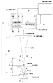
図1は、マイクロフォーカス立体X線検査装置を示し、このX線検査装置は、被検体TにX線を照射するX線発生器1と、被検体Tが固定される固定台としてのXYZテーブル2と、X線発生器1に対向して配置されたX線受像素子3と、このX線受像素子3に電気的に接続された画像処理装置としての画像処理ユニット4と、この画像処理ユニット4に電気的に接続された画像表示装置5とを、それぞれ備えている。
FIG. 1 shows a microfocus stereoscopic X-ray inspection apparatus. This X-ray inspection apparatus includes an
X線発生器1は、電子ビームBを照射する図示しない電子ビーム照射器と、この電子ビーム照射器から照射された電子ビームBを、磁界を形成することで偏向させる複数の電磁コイルと、電子ビームBによる制動放射にてX線を外部に放出する透過型ターゲットとをそれぞれ有し、X線受像素子3と略平行な平面としてのターゲット面TP上でX線発生源としての焦点Fを移動可能となっている。
The
XYZテーブル2は、X線発生器1とX線受像素子3との間に位置し、X線受像素子3と平行すなわちX線発生器1のターゲット面TPと平行に配置され、このターゲット面TPに対して平行かつ互いに直交する2方向であるX方向およびY方向にそれぞれ移動可能に設けられるとともに、X線発生器1とX線受像素子3とのそれぞれの中心を結ぶ中心軸Aと一致するようにZ方向に移動可能に設けられている。そして、このXYZテーブル2は、外部信号に応じてXYZ各方向へとそれぞれ移動することで、被検体TのXY位置および撮像拡大率Mを調整可能となっている。
The XYZ table 2 is located between the
X線受像素子3は、例えばイメージインテンシファイア、あるいは平面X線検出器などであり、X線発生器1から照射され被検体Tを透過したX線像を画像信号としてのX線透視画像G1に変換して受像するものである。
The X-ray image receiving element 3 is, for example, an image intensifier or a planar X-ray detector, and an X-ray fluoroscopic image using an X-ray image irradiated from the
画像処理ユニット4は、X線受像素子3で受像したX線透視画像G1の画像信号を得て例えば積分処理などにより一時的に記憶するとともに、この画像信号を信号処理して画像表示装置5に出力するものである。 The image processing unit 4 obtains an image signal of the X-ray fluoroscopic image G1 received by the X-ray image receiving element 3 and temporarily stores it, for example, by integration processing, and performs signal processing on the image signal to perform an image display device 5. Is output.
また、この画像処理ユニット4は、X線発生器1に電気的に接続され、このX線発生器1に、焦点Fの位置を決める焦点移動信号FSを出力可能となっている。
The image processing unit 4 is electrically connected to the
さらに、この画像処理ユニット4は、直視画像メモリ11と、立体透視画像メモリ12とを有している。
The image processing unit 4 further includes a direct
直視画像メモリ11は、ターゲット面TPに略垂直な被検体Tの中心線(本実施の形態では中心軸Aに一致)とターゲット面TPとの交差位置である中心位置Cを焦点FとしてX線発生器1から照射されたX線によるX線透視画像G1に基づいて直視透視画像GDを生成して記憶するものである。
The direct-
立体透視画像メモリ12は、中心位置CとX線受像素子3の中心とを結ぶ中心線(本実施の形態では中心軸Aに一致)に対して互いに線対称な位置である右位置Rと左位置Lとをそれぞれ焦点FとしてX線発生器1から照射されたX線による右眼透視画像GRおよび左眼透視画像GLに基づいて生成された立体透視画像GSを生成して記憶するものである。そして、この立体透視画像メモリ12は、右眼透視画像GRが記憶される右眼透視画像メモリMRと、左眼透視画像GLが記憶される左眼透視画像メモリMLとを備えている。
The
さらに、この画像処理ユニット4は、外部からの表示切換信号Sにより、直視透視画像GDと立体透視画像GSとを選択的に画像表示装置5に出力可能となっている。 Further, the image processing unit 4 can selectively output the direct-view fluoroscopic image GD and the stereoscopic fluoroscopic image GS to the image display device 5 by a display switching signal S from the outside.
画像表示装置5は、画像処理ユニット4から出力された処理画像である、直視透視画像GDと立体透視画像GSとをそれぞれ表示可能なモニタなどであり、外部からの表示切換信号Sにより、直視透視画像GDと立体透視画像GSとを選択的に表示可能とする。 The image display device 5 is a monitor or the like that can display a direct-view fluoroscopic image GD and a stereoscopic fluoroscopic image GS, which are processed images output from the image processing unit 4, and the direct-view fluoroscopy according to a display switching signal S from the outside. The image GD and the stereoscopic image GS can be selectively displayed.
そして、立体透視画像GSを立体的に透視する際には、例えば各透視画像GL,GRを偏光めがねに同期させて交互に表示するいわゆるステレオビューワ、一方を赤色に他方を青色にそれぞれ着色した各透視画像GL,GRを、赤色および青色のそれぞれに着色した左右のレンズを有するめがねにより立体的に透視するもの、画像表示面の視野角を調整して表示するもの、あるいはシャッタめがねを用いるものなど、検査者の視覚により立体的認識可能な様々な立体視装置を使用することが可能である。また、画像表示装置5自体を、正面に検査者が立つと立体透視画像GSが立体に見えるブラウン管、あるいは液晶モニタなどの表示装置とすることもできる。 When stereoscopically viewing the stereoscopic image GS, for example, the stereoscopic images GL and GR are alternately displayed in synchronization with polarized glasses, so-called stereo viewers, each colored in red and the other in blue Perspective images GL and GR that are viewed three-dimensionally with glasses having left and right lenses colored in red and blue, those that display images with the viewing angle of the image display surface adjusted, or those that use shutter glasses, etc. It is possible to use various stereoscopic devices that can be stereoscopically recognized by the examiner's vision. Further, the image display device 5 itself may be a display device such as a cathode ray tube or a liquid crystal monitor in which the stereoscopic fluoroscopic image GS looks three-dimensional when an inspector stands in front.
次に、上記一実施の形態によるX線透視画像の撮像方法を説明する。 Next, an X-ray fluoroscopic image capturing method according to the above embodiment will be described.
まず、被検体TをXYZテーブル2に固定し、直視透視画像GDを用いて被検体Tの撮像範囲および撮像拡大率Mを、XYZテーブル2の移動により調整する。 First, the subject T is fixed to the XYZ table 2, and the imaging range and the imaging magnification M of the subject T are adjusted by moving the XYZ table 2 using the direct-view fluoroscopic image GD.
このとき、画像処理ユニット4は、X線発生器1へ焦点Fがターゲット面TPの中心位置Cに位置するように焦点移動信号FSを出力し、画像表示装置5へと直視透視画像GDを出力する。
At this time, the image processing unit 4 outputs a focus movement signal FS to the
次いで、画像処理ユニット4は、X線発生器1へ焦点Fがターゲット面TPの右位置Rに位置するように焦点移動信号FSを出力し、この右位置Rに位置した焦点Fから照射されたX線により撮像されたX線受像素子3の右眼透視画像GRを、右眼透視画像メモリMRに記憶する。
Next, the image processing unit 4 outputs a focus movement signal FS to the
同様に、画像処理ユニット4は、X線発生器1へ焦点Fがターゲット面TPの左位置Lに位置するように焦点移動信号FSを出力し、この左位置Lに位置した焦点Fから照射されたX線により撮像されたX線受像素子3の左眼透視画像GLを、左眼透視画像メモリMLに記憶する。
Similarly, the image processing unit 4 outputs a focus movement signal FS to the
そして、画像処理ユニット4は、各透視画像GL,GRを画像処理した立体透視画像GSを立体透視画像メモリ12に記憶し、この立体透視画像GSを画像表示装置5へと出力する。
Then, the image processing unit 4 stores the stereoscopic fluoroscopic image GS obtained by performing image processing on the fluoroscopic images GL and GR in the stereoscopic
この後、画像表示装置5は、外部からの表示切換信号Sにより、立体透視画像GSを表示する。 Thereafter, the image display device 5 displays the stereoscopic image GS in response to a display switching signal S from the outside.
そして、検査者は、各種立体視装置を使用することにより、被検体Tの立体透視画像GSを立体的に認識する。 Then, the examiner recognizes the stereoscopic fluoroscopic image GS of the subject T in a three-dimensional manner by using various stereoscopic devices.
具体的に、検査者が認識する被検体Tの撮像拡大率Mは、X線発生器1、X線受像素子3および被検体Tの位置で決まるX線撮像系の拡大率をM1とし、画像表示装置5に表示されるX線透視画像G1の拡大率をM2とすると、M=M1×M2で表される。
Specifically, the imaging magnification M of the subject T recognized by the examiner is M1, which is the magnification of the X-ray imaging system determined by the positions of the
ここで、拡大率M1は、ターゲット面TPから被検体Tの中心までの距離をD1、ターゲット面TPからX線受像素子3までの距離をD2とすると、M1=D2/D1で求められ、拡大率M2は、約3〜6倍である。 Here, the enlargement ratio M1 is obtained by M1 = D2 / D1, where D1 is the distance from the target surface TP to the center of the subject T, and D2 is the distance from the target surface TP to the X-ray receiving element 3. The enlargement ratio M2 is about 3 to 6 times.
すなわち、この撮像拡大率Mにより、被験者は、被検体Tから距離D3の位置にある仮想視点Vから被検体TのX線透視画像を見ていることと等しくなる。なお、距離D3は、被検体Tの中心からX線受像素子3までの距離をD4とすると、D3=D4/M1で求められる。 That is, the imaging magnification M is equivalent to the subject viewing the X-ray fluoroscopic image of the subject T from the virtual viewpoint V located at a distance D3 from the subject T. The distance D3 is obtained by D3 = D4 / M1, where D4 is the distance from the center of the subject T to the X-ray image receiving element 3.
そして、仮想視点Vにおける仮想右眼VRと仮想左眼VLとの間隔Δ1は、検査者の右眼と左眼との間隔Δと撮像拡大率Mとにより、Δ1=Δ/Mで求められる。 The interval Δ1 between the virtual right eye VR and the virtual left eye VL at the virtual viewpoint V is obtained by Δ1 = Δ / M based on the interval Δ between the right eye and the left eye of the examiner and the imaging magnification M.
また、X線発生器1の右焦点と左焦点との間隔Δ2は、距離D1と距離D3とにより、Δ2=Δ1×D1/D3で求められる。
Further, the distance Δ2 between the right focus and the left focus of the
そして、一般的に、検査者の右眼と左眼との間隔は、約60mm程度であり、例えば、撮像拡大率Mが60倍のとき、Δ2は約1mm程度、撮像拡大率Mが120倍のときΔ2は約0.5mm程度に調整する。 In general, the interval between the right eye and the left eye of the examiner is about 60 mm. For example, when the imaging magnification M is 60 times, Δ2 is about 1 mm and the imaging magnification M is 120 times. In this case, Δ2 is adjusted to about 0.5 mm.
上述したように、上記一実施の形態によれば、ターゲット面TPの中心位置Cを焦点FとしてX線発生器1から照射されたX線によりX線受像素子3で受像したX線透視画像G1に基づいて画像処理ユニット4で直視透視画像GDを出力できることで、直視透視画像GDを確実に得ることができる。
As described above, according to the above-described embodiment, an X-ray fluoroscopic image received by the X-ray image receiving element 3 with X-rays irradiated from the
同時に、ターゲット面TP上の各位置R,Lをそれぞれ焦点FとしてX線発生器1から照射されたX線によりX線受像素子3で受像した各透視画像GR,GLに基づいて立体透視画像GSを画像処理ユニット4で出力できることで、例えばX線発生器1などを傾斜させる傾斜機構などを設ける場合と比較して、X線発生器1などがXYZテーブル2と干渉することなどもなく、X線検査装置全体の構成を簡略化しつつ充分な撮像拡大率Mを確保できる。
At the same time, the three-dimensional perspective image is based on the perspective images GR and GL received by the X-ray receiving element 3 by the X-rays irradiated from the
しかも、立体透視画像GSは、被検体Tの立体画像ではなく、右眼透視画像GRと左目透視画像GLとの合成により被検体Tを立体的に透視するものであるから、立体画像を生成する場合と比較して、立体透視画像GSを容易に生成でき、画像処理ユニット4の構成を簡略化できる。 In addition, the stereoscopic fluoroscopic image GS is not a stereoscopic image of the subject T, but a stereoscopic perspective is generated by synthesizing the right eye fluoroscopic image GR and the left eye fluoroscopic image GL. Compared to the case, the stereoscopic fluoroscopic image GS can be easily generated, and the configuration of the image processing unit 4 can be simplified.
また、このようにX線検査装置全体の構成を簡略化できることで、X線検査装置を小型化したり、製造コストを抑制したりすることが可能になる。 In addition, since the configuration of the entire X-ray inspection apparatus can be simplified in this way, it is possible to reduce the size of the X-ray inspection apparatus or to reduce manufacturing costs.
さらに、立体透視画像GSを、各種立体視装置により検査者が立体的に透視できるので、検査者の視覚に訴えたX線透視画像を画像表示装置5で表示できる。 Furthermore, since the examiner can see the stereoscopic fluoroscopic image GS three-dimensionally with various stereoscopic vision devices, the X-ray fluoroscopic image appealing to the vision of the examiner can be displayed on the image display device 5.
また、被検体Tを固定するXYZテーブル2を、X線受像素子3と平行かつ互いに交差するXY方向、および、X線発生器1とX線受像素子3とのそれぞれの中心を結ぶ中心軸Aに沿ったZ方向にそれぞれ移動可能とすることで、被検体TのXY位置および撮像拡大率Mを容易かつ任意に調整できる。
Further, the XYZ table 2 that fixes the subject T is connected to the X-ray image receiving element 3 in the X and Y directions that intersect with each other and the centers of the
1 X線発生器
2 固定台としてのXYZテーブル
3 X線受像素子
4 画像処理装置としての画像処理ユニット
5 画像表示装置
A 中心軸
F 焦点
G1 X線透視画像
GD 直視透視画像
GS 立体透視画像
T 被検体
TP 平面としてのターゲット面
DESCRIPTION OF
G1 X-ray fluoroscopic image
GD direct view fluoroscopy image
GS Stereoscopic image T Subject
Target surface as TP plane
Claims (3)
このX線発生器に対向して配置され、前記X線発生器で照射したX線による被検体のX線透視画像を受像するX線受像素子と、
このX線受像素子で受像したX線透視画像を処理した処理画像を出力する画像処理装置と、
この画像処理装置から出力された処理画像を表示可能な画像表示装置とを具備し、
前記X線発生器は、前記X線受像素子に略平行な平面上で焦点を移動可能であり、
前記画像処理装置は、前記平面に対して略垂直な前記被検体の中心線と前記平面との交差位置を焦点として前記X線発生器から照射されたX線により前記X線受像素子で受像されたX線透視画像に基づく直視透視画像と、前記中心線に対して互いに線対称な前記平面上の一対の位置をそれぞれ焦点として前記X線発生器から照射されたX線により前記X線受像素子で受像された各X線透視画像に基づく立体的に透視可能な立体透視画像とを、それぞれ出力可能である
ことを特徴としたX線検査装置。 An X-ray generator for irradiating the subject with X-rays;
An X-ray image receiving element disposed opposite to the X-ray generator and receiving an X-ray fluoroscopic image of the subject by the X-rays irradiated by the X-ray generator;
An image processing apparatus that outputs a processed image obtained by processing an X-ray fluoroscopic image received by the X-ray image receiving element;
An image display device capable of displaying the processed image output from the image processing device,
The X-ray generator is capable of moving a focal point on a plane substantially parallel to the X-ray receiving element;
The image processing apparatus receives an image on the X-ray image receiving element by X-rays emitted from the X-ray generator with a position where the center line of the subject substantially perpendicular to the plane intersects the plane. The X-ray reception is performed by a direct-view fluoroscopic image based on the X-ray fluoroscopic image and an X-ray irradiated from the X-ray generator with a pair of positions on the plane symmetrical to the center line as a focus. An X-ray inspection apparatus characterized by being capable of outputting a stereoscopically transparent image based on each X-ray transparent image received by an image element.
ことを特徴とした請求項1または2記載のX線検査装置。 The X-ray inspection apparatus according to claim 1, wherein the image processing apparatus is capable of selectively outputting a direct fluoroscopic image and a stereoscopic fluoroscopic image.
ことを特徴とした請求項1または2記載のX線検査装置。 The subject is fixed and can be moved in two directions parallel to and intersecting with the X-ray image receiving element and along the central axis connecting the centers of the X-ray generator and the X-ray image receiving element. The X-ray inspection apparatus according to claim 1, further comprising a fixed base.
Priority Applications (1)
| Application Number | Priority Date | Filing Date | Title |
|---|---|---|---|
| JP2004108128A JP2005291950A (en) | 2004-03-31 | 2004-03-31 | X-ray inspection equipment |
Applications Claiming Priority (1)
| Application Number | Priority Date | Filing Date | Title |
|---|---|---|---|
| JP2004108128A JP2005291950A (en) | 2004-03-31 | 2004-03-31 | X-ray inspection equipment |
Publications (1)
| Publication Number | Publication Date |
|---|---|
| JP2005291950A true JP2005291950A (en) | 2005-10-20 |
Family
ID=35325035
Family Applications (1)
| Application Number | Title | Priority Date | Filing Date |
|---|---|---|---|
| JP2004108128A Pending JP2005291950A (en) | 2004-03-31 | 2004-03-31 | X-ray inspection equipment |
Country Status (1)
| Country | Link |
|---|---|
| JP (1) | JP2005291950A (en) |
Citations (5)
| Publication number | Priority date | Publication date | Assignee | Title |
|---|---|---|---|---|
| JPS62227319A (en) * | 1986-03-31 | 1987-10-06 | 株式会社東芝 | X-ray stereoscopic apparatus |
| JPH01246796A (en) * | 1988-03-28 | 1989-10-02 | Hitachi Medical Corp | X-ray inspection device |
| JP2002527857A (en) * | 1998-10-06 | 2002-08-27 | カーディアク・マリナーズ・インコーポレイテッド | X-ray scanning method and apparatus |
| JP2003090808A (en) * | 2002-07-23 | 2003-03-28 | Hamamatsu Photonics Kk | X-ray inspection device |
| JP2003245274A (en) * | 2002-02-27 | 2003-09-02 | Canon Inc | Radiation imaging apparatus, radiation imaging method, radiation image display apparatus, and radiation image display method |
-
2004
- 2004-03-31 JP JP2004108128A patent/JP2005291950A/en active Pending
Patent Citations (5)
| Publication number | Priority date | Publication date | Assignee | Title |
|---|---|---|---|---|
| JPS62227319A (en) * | 1986-03-31 | 1987-10-06 | 株式会社東芝 | X-ray stereoscopic apparatus |
| JPH01246796A (en) * | 1988-03-28 | 1989-10-02 | Hitachi Medical Corp | X-ray inspection device |
| JP2002527857A (en) * | 1998-10-06 | 2002-08-27 | カーディアク・マリナーズ・インコーポレイテッド | X-ray scanning method and apparatus |
| JP2003245274A (en) * | 2002-02-27 | 2003-09-02 | Canon Inc | Radiation imaging apparatus, radiation imaging method, radiation image display apparatus, and radiation image display method |
| JP2003090808A (en) * | 2002-07-23 | 2003-03-28 | Hamamatsu Photonics Kk | X-ray inspection device |
Similar Documents
| Publication | Publication Date | Title |
|---|---|---|
| KR101436218B1 (en) | Charged particle beam device and image display method | |
| JP2010526558A (en) | X-ray generator for producing stereoscopic visual effects and medical X-ray equipment employing the same | |
| JP2020508496A (en) | Microscope device for capturing and displaying a three-dimensional image of a sample | |
| US20120050277A1 (en) | Stereoscopic image displaying method and device | |
| JPH095643A (en) | Stereoscopic endoscope device | |
| JP2014526335A (en) | Viewing live 3DX rays | |
| JP2007229201A (en) | Stereoscopic mammography apparatus | |
| US20120249533A1 (en) | Stereoscopic display apparatus | |
| JP2012213583A (en) | Stereoscopic display apparatus | |
| JP2842735B2 (en) | Multi-viewpoint three-dimensional image input device, image synthesizing device, and image output device thereof | |
| JP2005291950A (en) | X-ray inspection equipment | |
| CN102985013A (en) | Medical image diagnosis device, image processing device, and ultrasound diagnosis device | |
| KR101967751B1 (en) | Non optical plate multiview 2d/3d conversion parallax lighting system | |
| JP5658818B2 (en) | Radiation breast image display method, radiation breast image display apparatus and program | |
| JP2002182154A (en) | Stereoscopic image display device | |
| JP2012110645A (en) | Device and method for displaying stereoscopic image | |
| JP2003050274A (en) | Device for visualizing simultaneously three-dimensional space and object emitting characteristic energy as stereoscopic vision in environment having poor visibility | |
| JP2012115380A (en) | Stereoscopic image acquiring method and apparatus | |
| JP2012024516A (en) | Radiological image radiographing and displaying method and apparatus | |
| JP2011158644A (en) | Display device | |
| WO2012132320A1 (en) | Stereoscopic image display apparatus and stereoscopic image display method | |
| JP2002296541A (en) | 3D image display device | |
| JPS63244992A (en) | Stereoscopic display device | |
| WO2012056682A1 (en) | 3d image display device | |
| JP2012105047A (en) | Stereoscopic image display device, method, and program |
Legal Events
| Date | Code | Title | Description |
|---|---|---|---|
| A621 | Written request for application examination |
Free format text: JAPANESE INTERMEDIATE CODE: A621 Effective date: 20070216 |
|
| A977 | Report on retrieval |
Free format text: JAPANESE INTERMEDIATE CODE: A971007 Effective date: 20090408 |
|
| A131 | Notification of reasons for refusal |
Free format text: JAPANESE INTERMEDIATE CODE: A131 Effective date: 20090415 |
|
| A521 | Written amendment |
Free format text: JAPANESE INTERMEDIATE CODE: A523 Effective date: 20090604 |
|
| A131 | Notification of reasons for refusal |
Free format text: JAPANESE INTERMEDIATE CODE: A131 Effective date: 20090819 |
|
| A521 | Written amendment |
Free format text: JAPANESE INTERMEDIATE CODE: A523 Effective date: 20090916 |
|
| A02 | Decision of refusal |
Free format text: JAPANESE INTERMEDIATE CODE: A02 Effective date: 20100120 |