JP2005292059A - Laser marking device - Google Patents
Laser marking device Download PDFInfo
- Publication number
- JP2005292059A JP2005292059A JP2004110505A JP2004110505A JP2005292059A JP 2005292059 A JP2005292059 A JP 2005292059A JP 2004110505 A JP2004110505 A JP 2004110505A JP 2004110505 A JP2004110505 A JP 2004110505A JP 2005292059 A JP2005292059 A JP 2005292059A
- Authority
- JP
- Japan
- Prior art keywords
- lens barrel
- laser
- marking device
- laser marking
- absorbing material
- Prior art date
- Legal status (The legal status is an assumption and is not a legal conclusion. Google has not performed a legal analysis and makes no representation as to the accuracy of the status listed.)
- Pending
Links
Images
Landscapes
- Laser Beam Processing (AREA)
Abstract
【課題】 精巧に調整されたライン光を形成するレーザ墨出し装置において、不用意に加えられる衝撃からレーザ墨出し装置を保護する機構を提供することにある。
【解決手段】 鏡胴103を揺動可能に懸架するジンバル装置103を塔載した固定板を緩衝材を介して支持板に固定し、さらに鏡胴102の下部周囲にも緩衝材を配置し、鏡胴102に加わる外力(衝撃)を2ヶ所に配置した衝撃緩衝材で受け、レーザ墨出し装置に不用意に加えられた衝撃からレーザ墨出し装置を保護するようにした。
【選択図】 図1
PROBLEM TO BE SOLVED: To provide a mechanism for protecting a laser marking device from a shock applied inadvertently in a laser marking device for forming a finely adjusted line light.
A fixing plate on which a gimbal device 103 for suspendably suspending a lens barrel 103 is fixed to a support plate via a buffer material, and a buffer material is also arranged around the lower portion of the lens barrel 102, The external force (impact) applied to the lens barrel 102 is received by impact buffering materials arranged at two locations, so that the laser marking device is protected from the shock applied to the laser marking device inadvertently.
[Selection] Figure 1
Description
本発明は衝撃吸収機構及び鏡胴の傾斜感知機構を有するレーザ墨出し装置に関するものである。 The present invention relates to a laser marking device having an impact absorbing mechanism and a lens barrel tilt sensing mechanism.
しかし、この作業は最低でも2人で行う必要があり、非常に手間が掛かり、効率が悪いという問題があった。この問題を改善するために、最近ではライン光照射機能を有するレーザ墨出し装置を用いて効率良く墨出し作業を行うことが多くなった。レーザ墨出し装置は1人で墨出し作業を容易に行うことができるため、建築作業には欠かせない建築作業必須ツールとなりつつある。 However, it is necessary to perform this work by at least two people, which is very troublesome and inefficient. Recently, in order to improve this problem, the ink marking work has been frequently performed efficiently using a laser marking device having a line light irradiation function. Since the laser marking device can be easily performed by one person, it is becoming an indispensable tool for building work.
墨出しラインには床から壁、天井にかけて垂直線を描くいわゆる『たちライン』や2本の『たちライン』を同時に照射させることで天井に直角ラインを描く『大矩ライン(おおがねライン)』あるいは壁に水平線を描く『ろくライン』あるいはレーザ墨出し装置の直下の床上に集光したレーザビームを照射する『地墨』等いろいろなラインが存在する。 The ink line is a so-called “tachi line” that draws a vertical line from the floor to the wall and ceiling, and two “tachi lines”. ”Or“ Roku Line ”that draws a horizontal line on the wall, or“ Goku ”that irradiates a focused laser beam on the floor just below the laser marking device.
これらのラインの精度は10m先で、ラインの水平度あるいは鉛直度が両端でほぼ±1mmという高精度になっている。しかし、本体に衝撃を加えるとラインを形成するロッドレンズ等の位置が変化しラインの精度が狂う傾向があるのが問題であった。 The accuracy of these lines is 10 m ahead, and the horizontal or verticality of the lines is as high as approximately ± 1 mm at both ends. However, when an impact is applied to the main body, the position of the rod lens or the like forming the line changes, and the accuracy of the line tends to go wrong.
耐衝撃性を高めるために、例えば特許文献1では以下のようにしている。墨出し装置はレーザ光源とダイオード光源を組込んだ鏡胴をジンバル装置に縣架して、レーザのスポットを鉛直上方測点に結像させ、またダイオ−ド光のスポットを鉛直下方床面上に、レーザのスポットと同軸に結像させるものである。風の影響でジンバル装置に縣架した鏡胴が揺れてスッポトが動くのを防止するために、装置を風防ケ−スで覆った。この風防ケ−スの内側の裾周に緩衝材を貼り、鏡胴が風防ケ−スに接触するとき衝撃を吸収する。さらに、緩衝材の表面を導電体とし、鏡胴にも接触部に導電体を設けて、装置が傾いて風防ケ−スと鏡胴が接触した場合、通電する回路を設けてレーザ光源とダイオード光源の電源を切断して、上下のスポットを消し墨出し装置の異常を使用者に知らせるようにした。 In order to improve the impact resistance, for example, Patent Document 1 does the following. The ink marking device mounts a lens barrel incorporating a laser light source and a diode light source on a gimbal device to form an image of the laser spot on the vertical upper measurement point, and the diode light spot on the vertical lower floor surface. In addition, an image is formed coaxially with the laser spot. In order to prevent the lens barrel mounted on the gimbal device from shaking and moving the spot under the influence of wind, the device was covered with a windshield case. A cushioning material is attached to the inner periphery of the windshield case to absorb the impact when the lens barrel comes into contact with the windshield case. Furthermore, the surface of the cushioning material is a conductor, and the lens barrel is also provided with a conductor at the contact portion. When the device is tilted and the windshield case and the lens barrel are in contact with each other, a circuit is provided to energize the laser light source and the diode. The light source was turned off, the upper and lower spots were erased, and the user was informed of abnormalities in the deinking device.
ところが、墨出し装置がスポット表示からライン表示に進歩して装置が複雑になった。このため衝撃により、ジンバル装置やレーザ光源の保持姿勢が変化したり、レーザのスポットをライン光に広げるロッドレンズの位置が変わると、ライン光が湾曲したり、水平度、鉛直度が変化してこれらの精度が低下することが問題となった。
このため、さらに効果的な衝撃対策方法が必要になった。
However, the inking device has progressed from spot display to line display, and the device has become complicated. For this reason, if the holding posture of the gimbal device or the laser light source changes due to the impact, or if the position of the rod lens that spreads the laser spot to the line light changes, the line light will be bent or the horizontality and verticality will change. The problem is that these precisions deteriorate.
For this reason, a more effective impact countermeasure method has become necessary.
本発明は上記のような従来の問題を解決したレーザ墨出し装置を提供することを目的とする。具体的には本発明の目的はジンバル装置を、衝撃吸収材を介して固定して衝撃を緩和し、さらに鏡胴下端の周囲にも衝撃吸収材を配置して、鏡胴が他の部品と接触するときの衝撃を緩和する。すなわち、墨出し装置のジンバル機構近傍と鏡胴が他の部品と接触する鏡胴下部近傍の2ヶ所に衝撃吸収手段を配し、鏡胴に加わる衝撃を緩和したレーザ墨出し装置を提供することにある。 An object of the present invention is to provide a laser marking device that solves the above-described conventional problems. Specifically, the object of the present invention is to fix the gimbal device via an impact absorbing material to alleviate the impact, and further dispose the impact absorbing material around the lower end of the lens barrel, so that the lens barrel is connected to other parts. Mitigates impact when touching. That is, to provide a laser marking device in which shock absorbing means are arranged at two locations near the gimbal mechanism of the marking device and near the lower portion of the barrel where the lens barrel contacts other parts, and the impact applied to the lens barrel is reduced. It is in.
また、鏡胴下端の周囲に配置した緩衝材保持リングと鏡胴が不時接触したとき、通電する回路によりレーザ光源の電源回路を遮断するレーザ墨出し装置を提供することにある。 It is another object of the present invention to provide a laser marking device that shuts off a power source circuit of a laser light source by an energized circuit when a buffer material holding ring arranged around the lower end of the lens barrel and the lens barrel are in contact with each other.
上記の目的を達成するために本発明は、レーザビームを発生するレーザ光源保持筒と、該レーザビームを分割して複数のビームを形成する少なくとも1個のハーフミラーを内蔵したビームスプリッタの保持筒と、該ビームスプリッタから出たレーザビームの通路を形成する複数のレーザビーム投射口筒を構成要素とする鏡胴を、鉛直に縣架するジンバル装置を衝撃吸収材を介して支持した固定板に固定したことに特徴がある。 To achieve the above object, the present invention provides a laser beam source holding cylinder for generating a laser beam and a beam splitter holding cylinder containing at least one half mirror for dividing the laser beam to form a plurality of beams. And a fixed plate that supports a gimbal device that vertically mounts a lens barrel having a plurality of laser beam projection apertures forming a passage for a laser beam emitted from the beam splitter via a shock absorber. It is characterized by being fixed.
本発明の他の特徴は、前記鏡胴の下端部の周囲に衝撃吸収材を配置し、該衝撃吸収材はボビン状の導電体に把持された状態で、レーザ墨出し装置の回転盤と同心に保持され、鏡胴が揺動し不時接触したときの衝撃を緩和したことにある。 Another feature of the present invention is that an impact absorbing material is disposed around the lower end of the lens barrel, and the impact absorbing material is held concentrically with a bobbin-shaped conductor and is concentric with the rotating disk of the laser marking device. And the impact is reduced when the lens barrel swings and makes contact with it.
本発明の他の特徴は、鏡胴下端周囲に配置した衝撃吸収材が、ボビン状導電体に把持され、レーザ墨出し装置の回転盤と同軸に保持され、さらに絶縁容器に収納され、該容器の蓋は導電体であり、該絶縁容器を固定するねじまたはボルトは絶縁体であることである。さらに円筒形の鏡胴下端と円筒形のボビン状導電体は、同軸に配置され、鏡胴が一定角以上振れると、導電体同士が接触することにある。
本発明の他の特徴及び利点は以下の説明により明瞭に理解される。
Another feature of the present invention is that the shock absorber disposed around the lower end of the lens barrel is held by a bobbin-like conductor, held coaxially with the rotating plate of the laser marking device, and further housed in an insulating container. The lid is a conductor, and the screw or bolt for fixing the insulating container is an insulator. Further, the lower end of the cylindrical lens barrel and the cylindrical bobbin-shaped conductor are arranged coaxially, and the conductors come into contact with each other when the lens barrel swings more than a certain angle.
Other features and advantages of the present invention will be clearly understood from the following description.
レーザビームを投射する鏡胴を揺動可能に懸架するジンバル装置を固定する固定板と、揺動する鏡胴が他の部品と接触する下部の対向部に衝撃吸収材を鏡胴と同心に設けたことにより、鏡胴はその上部と下部の2ヶ所で衝撃を緩和できるようになった。これにより鏡胴に塔載されたレーザ管、ビームスプリッタやロッドレンズ及びロッドレンズホルダ等にかかる衝撃が軽減された。また、ジンバル装置も衝撃吸収材で支持された固定板に固定されたので、衝撃が著しく軽減された。 A fixed plate that fixes the gimbal device that suspends the lens barrel that projects the laser beam in a swingable manner, and a shock absorber is provided concentrically with the lower part where the swinging lens barrel contacts other parts. As a result, the lens barrel can relieve shock at two locations, the upper and lower parts. As a result, the impact on the laser tube, beam splitter, rod lens, rod lens holder and the like mounted on the lens barrel was reduced. Moreover, since the gimbal device was also fixed to the fixed plate supported by the shock absorbing material, the impact was remarkably reduced.
衝撃吸収材を設けたことにより、レーザ墨出し装置に与えられた不用意な衝撃からレーザ墨出し装置を保護することができる。 By providing the shock absorbing material, the laser marking device can be protected from inadvertent impact given to the laser marking device.
以下本発明にかかるレーザ墨出し装置の実施形態について図1〜図10を参照して説明する。
(実施形態1)
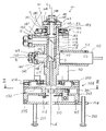
本発明の縦断面図を示す図1のように、本発明に係るレーザ墨出し装置101は、レーザビームを投射する鏡胴102と、この鏡胴102を鉛直に縣架するジンバル装置103と、鏡胴102から投射するレーザビームを所定の位置に調整する回転盤部104から構成される。
Embodiments of a laser marking device according to the present invention will be described below with reference to FIGS.
(Embodiment 1)
As shown in FIG. 1 showing a longitudinal sectional view of the present invention, a
鉛直に縣架された鏡胴102の側壁にほぼ直角方向に延びるレーザ管保持筒111が設けられ、鏡胴102の鉛直軸とほぼ直角方向にレーザ管(レーザ光源)110が保持されている。レーザ管110は、その円周に120°の間隔で3本ずつ配置された2組のネジ112でレーザ管保持筒111に固定される。すなわち、このネジ112により、レーザ管110をレーザ管保持筒112の軸上に位置するように調整することができる。
A laser tube holding cylinder 111 extending in a substantially right angle direction is provided on a side wall of the
上記鏡胴102の内部には中実のビームスプリッタ115が、鉛直同軸上にスプリッタホルダ116内に収納され固定されている。ビームスプリッタ115とスプリッタホルダ116とは接着等の方法により固定される。スプリッタホルダ116は鏡胴102の上部に120°の間隔で配置した3本のネジ(図示せず)と下部に120°の間隔で配置した3本のネジ117で固定される。これら6本のネジ117により、ビームスプリッタ115の位置を調整することができる。ビームスプリッタ115には適切な間隔をおいて2個所に45°のハーフミラー面118とハーフミラー面119が形成されている。すなわち、レーザ管110
からのビームaは第1のハーフミラー面118を透過して水平ライン光bを形成するために用いられ、該ハーフミラー面118を反射したビームは更に、第2のハーフミラー面119で二分され、一つは透過して垂直ライン光cを形成するために用いられる。また該ハーフミラー面119で直角方向に反射したビームは別の垂直ライン光eを形成するために用いられる。またビームスプリッタ115の上面で反射して下方に直進したビームdは地墨用のビームになる。本発明においては、上記第1及び第2のハーフミラー面を有する複数の光学部材が一体的に形成され、上記のスプリッタホルダ116に収納されているので、ネジ117によりビームスプリッタ115の位置を調整することができる。
A solid beam splitter 115 is housed and fixed in a
The beam a from the first
鏡胴102には次の4つのレーザビームの投射口筒が設けられる。レーザ管保持筒111の反対側に第1のレーザ投射口筒130が設けられ、さらにこの上方に第2のレーザ投射口筒131が設けられる。また、鏡胴102の上方には第3のレーザ投射口筒132、下方には第4のレーザ投射口筒133が設けられている。
The
これらのレーザ投射口筒130〜133に対応したスプリッタホルダ116の位置に穴が形成され、この穴を通してレーザビームが各レーザ投射口筒130〜133に導かれる。
A hole is formed at the position of the
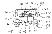
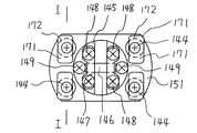
第1のレーザ投射口筒130にはフランジ140が形成され、対向する出射側には図4に示すようにフランジ141がネジ144で固定される。フランジ141には図4に示すようにロッドレンズホルダ145がネジ149で固定される。ロッドレンズ146は鏡胴102軸方向、即ち垂直姿勢でロッドレンズホルダ145に一対のレンズおさえ147を介してネジ148で固定される。
A
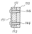
第2のレーザ射口筒131にはフランジ150が形成される。対向する出射側にはフランジ151が図5に示すようにネジ144で固定される。さらにロッドレンズホルダ145がネジ149で固定される。ロッドレンズ146は鏡胴102軸と直角方向、すなわち水平方向に、ロッドレンズホルダ145にレンズおさえ147を介してネジ148で固定される。
A
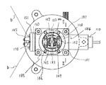
第3のレーザ射口筒132には図1に示すようにフランジ160が固定される。すなわちレーザ投射口筒132の周面に120°の間隔で設けられた3本のネジ161で固定される。対向する出射側にはフランジ162がネジ144で固定され、さらにレンズホルダ145がネジ149で固定される。ロッドレンズ146は、図3に示すようにレンズおさえ147を介してネジ148で固定される。ロッドレンズ146はレーザ管110と平行に取付けられる。
As shown in FIG. 1, a flange 160 is fixed to the third laser injection tube 132. That is, it is fixed on the peripheral surface of the laser projection tube 132 with three
上記の3個のフランジ141、151及び162とロッドレンズホルダ145の間には図3に示すようにピン170が取付けられ、これを支点としてロッドレンズホルダ145の取付け角度を調整できるように構成されている。
A
また、各フランジ140、150及び160とこれに対向するフランジ141、フランジ151、フランジ162とはネジ144によって固定される。ネジ144を通すための穴172は図4、図5及び図6に示すように十分大きくしてあるので、ワッシャ171が用いられる。すなわち、レーザ投射口筒130〜133の端部に取り付けたフランジ140、150、160と、ロッドレンズ146を搭載したフランジ141、151、162との相対的な位置を調整できるように穴172が設けられ、調整後ネジ144で固定できるように構成されているが、穴のサイズはネジ144の周囲に1mm以上の間隙を有する程度であることが望ましい。
The
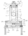
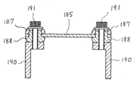
一方、図1に示すジンバル装置103は同一面上の2軸を有する構造よりなる。鏡胴102の上部に設けた一対の軸受け180に小リング181から突出した一対のピン183(図1、図2、図3)で揺動自在に取付けられる。また、この小リング181には前述した軸受け180の位置と90°位相が異なる位置にもう一組の軸受け182が設けられる。大リング184から突出した一対のピン183でリング同士が揺動自在に取付けられる。ピン183は各リング181、184と螺合する。これによりX方向Y方向の揺動ができ、鏡胴102を垂直に保持することができる。このジンバル装置103は図2に示すように固定板185にボルト186で固定される。図7に示すように固定板185は4組のブッシュ187とブッシュ188を介して一対の支持板190にボルト191で固定され、支持板190は回転盤部104にボルト192で固定される(図2)。
On the other hand, the
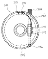
回転盤部104は図1及び図2に示すように回転盤200と回転調整盤201と固定盤202等からなる。3本のボルト203は基板204と螺合し、回転盤部104を水平に保つ。基板204は固定盤202にネジ205で固定される。この固定盤202には図9に示すように、回転操作ができるツマミを持つ軸210が組込まれ、一端はキャップ206が回転可能に係合され軸210の移動が規制される。軸210の中央にはネジが加工され、移動体207がこのネジと螺合している。移動体207にはバンド208がボルト211で固定される。移動体207が占める固定盤202の平面部には長方形の開口部が移動範囲を含めて設けられる。図1に示すように固定盤202の中心軸を同軸として回転調整盤201が、ボルト212で固定された押さえ板213により回転可能に嵌合取付けされる。弧状のバンド208の一端は回転調整盤201の円筒部の内面にネジ214及びナット215(図9)で固定される。
As shown in FIGS. 1 and 2, the
回転盤200は回転調整盤201と同軸上に回転可能に嵌合される。回転調整盤201の嵌合円筒部にV形溝が設けられ、回転盤200の側面から突出するボール付き止めネジ216により抜け防止が施される。
The
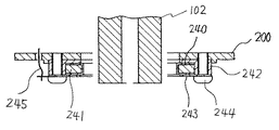
図8に示すように、回転盤200の下部には、ボビン状導電体240がゴム241を装着し絶縁材で作られたケ−ス242に収納され、導電体によるフタ243が絶縁材のネジ244で固定される。鏡胴102下端の円筒部とボビン状導電体240は同軸に取付けられる。フタ243にはリード線245が接続される。
As shown in FIG. 8, a bobbin-
回転盤200には一対の支持板190がボルト230で固定されており、鏡胴102は回転盤200の回転により任意の方向に向くことができる。
A pair of
次にレーザ光の投射について説明する。レーザ管(レーザ光源)110からビームを投射する。レーザビームaは直進し、第1のレーザ投射口筒130内を通過し、ロッドレンズ146で水平方向の扇状ライン光bに変換され、壁等に水平ラインを描く。一方、第1のハーフミラー面118に当ったレーザビームの一部は直角に反射してビームスプリッタ115内を直進し、上部にある第3のレーザ投射口筒132内を通過してロッドレンズ146でレーザ管110と直角方向の扇面状ライン光cに変換され、天井等にラインを描く。また、レーザビームの一部がビームスプリッタ115の上面で反射し、下方に直進して、本装置を固定した面にレーザビームdを照射し、これが地墨となる。
Next, laser light projection will be described. A beam is projected from a laser tube (laser light source) 110. The laser beam a travels straight, passes through the first
また、上方に直進したレーザビームの一部が第2のハーフミラー119で直角に反射し、第2のレーザ投射口筒131内を通過してロッドレンズ146に照射される。この照射ビームはロッドレンズ146で垂直方向の扇面状ライン光eに変換され、壁面から天井にかけてラインを描く。
Further, a part of the laser beam that has traveled straight upward is reflected at a right angle by the
次に鏡胴に加わる衝撃吸収方法について説明する。
まず、レーザ墨出し装置の落下等により、ジンバル機構103に衝撃が伝わる場合は、ジンバル装置103が固定された固定板185が一対のブッシュ187とブッシュ188を用いて支持板190にボルト191で固定されているので、一対のブッシュの垂直方向及び水平方向の変形により衝撃を吸収する。衝撃吸収後は一対のブッシュ187及びブッシュ188は弾性により元の形状に戻るので、レーザビームdの照射位置(地墨)は変わらない。その他のラインにも支障は発生しない。
(実施形態2)
また、鏡胴102がジンバル装置103のピン183を支点にして勢いよく振れた場合は、鏡胴102の下部が241を装着したボビン状導電体240に衝突するとが該ゴム241が変形し該ボビン状導電体の位置が変位して衝撃を吸収する。
また、前述のゴム241を装着したボビン状導電体240は回転盤200から絶縁されているので、導電性の鏡胴102が接触すると 鏡胴102、ボビン状導電体240、フタ243、リード線245、支持板185、鏡胴102という導通回路が形成される。従って、鏡胴102とボビン状導電体240間でスイッチの役目をさせることが可能である。つまり、墨出し装置が傾いて置かれた時、鏡胴とボビン状導電体が接触すると、レーザ管の電源を切断することができる。
(実施形態3)
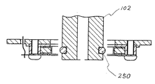
さらに図10に示すように、鏡胴102がジンバル装置103のピン183を支点にして勢いよく振れた時、鏡胴102の下部に設けた溝に嵌めた導電性のOリング250が対向する壁に当り、Oリング250の変形により衝撃を吸収する。
(実施形態4)
実施形態1と実施形態2を組合せて実施したものである。
(実施形態5)
実施形態1と実施形態3を組合せて実施したものである。
(実施形態6)
実施形態2と実施形態3を組合せて実施したものである。
(実施形態7)
実施形態1と実施形態2と実施形態3を組合せて実施したものである。ゴム241及びOリング250の材質はフッ素系、シリコン系、ニトリル系、ウレタン系のゴムや天然ゴムが使用できる。また、ゴムの代りにスポンジ等を緩衝材の形状にして使用することができる。さらにゲル材を使用することもできる。また、ブッシュ187、188の材質も前記ゴムやOリングに使用した材料を使用することができる。
Next, an impact absorbing method applied to the lens barrel will be described.
First, when an impact is transmitted to the
(Embodiment 2)
When the
In addition, since the bobbin-shaped
(Embodiment 3)
Further, as shown in FIG. 10, when the
(Embodiment 4)
This is a combination of Embodiment 1 and Embodiment 2.
(Embodiment 5)
This is a combination of the first and third embodiments.
(Embodiment 6)
This is a combination of the second embodiment and the third embodiment.
(Embodiment 7)
This is a combination of Embodiment 1, Embodiment 2, and Embodiment 3. As the material of the
101:レーザ墨出し装置 102:鏡胴 103:ジンバル装置 104:回転盤部 110:レーザ管(レーザ光源) 111:レーザ管保持筒 112:レーザ管固定ネジ 115:ビームスプリッタ 116:スプリッタホルダ 117:スプリッタホルダ固定ネジ 118、119:第1及び第2のハーフミラー面 130〜133:第1〜第4のレーザ投射口筒 140、141:フランジ 144、149、161、205、214:ネジ 145:ロッドレンズホルダ 146:ロッドレンズ 147:レンズおさえ 148:ネジ 150、151、160、162:フランジ 170、183:ピン 171:ワッシャ 172:穴 180、182:軸受け 181:小リング 184:大リング 185:固定板 186、191、192、203、211、212:ボルト 187、188:ブッシュ 190:支持板 200:回転盤 201:回転調整盤 202:固定盤 204:基板 206:キャップ 207:移動体 208:バンド 210:軸 213:押え板 215:ナット 240:ボビン状導電体 241:ゴム 242:ケ−ス 243:フタ 244:ネジ 245:リード線 250:Oリング
DESCRIPTION OF SYMBOLS 101: Laser marking apparatus 102: Lens barrel 103: Gimbal apparatus 104: Turntable part 110: Laser tube (laser light source) 111: Laser tube holding cylinder 112: Laser tube fixing screw 115: Beam splitter 116: Splitter holder 117: Splitter
Claims (8)
前記鏡胴の支持部近傍と鏡胴の下部周囲の少なくとも1ヶ所以上に衝撃吸収材を配置したことを特徴とするレーザ墨出し装置。 A laser light source that emits a laser beam and an optical component that converts the laser beam and projects line light, and a gimbal device that suspends the lens barrel so as to be swingable.
A laser marking device, characterized in that an impact absorbing material is disposed in at least one place near the support portion of the lens barrel and around the lower portion of the lens barrel.
前記ジンバル装置を塔載した固定板を衝撃吸収材を介して支持板に固定したことを特徴とするレーザ墨出し装置。 A laser light source for emitting a laser beam and an optical system for projecting line light by converting the laser beam, and a gimbal device for suspending a lens barrel so as to be swingable.
A laser marking device characterized in that a fixed plate on which the gimbal device is mounted is fixed to a support plate via an impact absorbing material.
前記ジンバル装置等を支持する支持板を固定する鏡胴下端部に位置する底板の内側に、該底板と同心に配置した絶縁ケースと該ケースに収納される衝撃吸収材及び鏡胴と接触可能な導電材からなる衝撃吸収材の保持材と導電性のフタからなるユニットを絶縁されたネジで前記底板に固定したことを特徴とするレーザ墨出し装置。 A laser light source for emitting a laser beam and an optical system for projecting line light by converting the laser beam, and a gimbal device for suspending a lens barrel so as to be swingable.
Insulating case arranged concentrically with the bottom plate inside the bottom plate located at the lower end of the lens barrel for fixing the support plate for supporting the gimbal device etc., and the shock absorbing material and the lens barrel accommodated in the case are accessible. A laser marking device characterized in that a shock absorbing material holding material made of a conductive material and a unit made of a conductive lid are fixed to the bottom plate with insulated screws.
前記ジンバル装置等を支持する支持板を固定する鏡胴下端外周部に導電材からなる衝撃吸収材を設けたことを特徴とするレーザ墨出し装置。 A laser light source for emitting a laser beam and an optical system for projecting line light by converting the laser beam, and a gimbal device for suspending a lens barrel so as to be swingable.
A laser marking device, characterized in that a shock absorbing material made of a conductive material is provided on the outer periphery of the lower end of a lens barrel for fixing a support plate for supporting the gimbal device or the like.
4. The laser marking device according to claim 3, wherein a shock absorbing material made of a conductive material is provided on an outer periphery of a lower end of a lens barrel for fixing a support plate for supporting the gimbal device or the like. .
Priority Applications (1)
| Application Number | Priority Date | Filing Date | Title |
|---|---|---|---|
| JP2004110505A JP2005292059A (en) | 2004-04-02 | 2004-04-02 | Laser marking device |
Applications Claiming Priority (1)
| Application Number | Priority Date | Filing Date | Title |
|---|---|---|---|
| JP2004110505A JP2005292059A (en) | 2004-04-02 | 2004-04-02 | Laser marking device |
Publications (2)
| Publication Number | Publication Date |
|---|---|
| JP2005292059A true JP2005292059A (en) | 2005-10-20 |
| JP2005292059A5 JP2005292059A5 (en) | 2007-05-24 |
Family
ID=35325136
Family Applications (1)
| Application Number | Title | Priority Date | Filing Date |
|---|---|---|---|
| JP2004110505A Pending JP2005292059A (en) | 2004-04-02 | 2004-04-02 | Laser marking device |
Country Status (1)
| Country | Link |
|---|---|
| JP (1) | JP2005292059A (en) |
Cited By (2)
| Publication number | Priority date | Publication date | Assignee | Title |
|---|---|---|---|---|
| JP2007278718A (en) * | 2006-04-03 | 2007-10-25 | Myzox:Kk | Laser marking device |
| JP2008157784A (en) * | 2006-12-25 | 2008-07-10 | Matsushita Electric Works Ltd | Adjusting method of marking laser device |
-
2004
- 2004-04-02 JP JP2004110505A patent/JP2005292059A/en active Pending
Cited By (2)
| Publication number | Priority date | Publication date | Assignee | Title |
|---|---|---|---|---|
| JP2007278718A (en) * | 2006-04-03 | 2007-10-25 | Myzox:Kk | Laser marking device |
| JP2008157784A (en) * | 2006-12-25 | 2008-07-10 | Matsushita Electric Works Ltd | Adjusting method of marking laser device |
Similar Documents
| Publication | Publication Date | Title |
|---|---|---|
| US5552886A (en) | Laser beam transmitting apparatus | |
| US20020092185A1 (en) | Compact optical calibrating apparatus for multiple orientations | |
| JPH01304308A (en) | Horizontally/vertically indexing apparatus with tilt compensation | |
| WO1997025591A1 (en) | Laser plumb bob and apparatus | |
| JP2010190640A (en) | Inclination measuring instrument | |
| US5724744A (en) | Self-leveling device mounted on a rotating base for projecting laser rays | |
| JP2009103583A (en) | Laser marking machine | |
| JP3938340B2 (en) | Dust-proof cover for laser marking device | |
| JP2005292059A (en) | Laser marking device | |
| JPH075392A (en) | Laser-beam projection device | |
| JP3148587B2 (en) | Laser device for ink marking | |
| JP4993554B2 (en) | Inking machine | |
| US3988837A (en) | Optical plumbing device | |
| JP3810231B2 (en) | Optical axis balance adjustment mechanism of laser marking device | |
| JP3435788B2 (en) | Laser floodlight | |
| JP2010210481A (en) | Inclination detector and laser marker | |
| JP2509510Y2 (en) | Plane setting device | |
| JP4628146B2 (en) | Laser marking machine | |
| JP2003329454A (en) | Laser marking device | |
| JP2009085909A (en) | Laser marking machine | |
| JP4257536B2 (en) | Inking machine | |
| JPH07243855A (en) | Visible light beam projector | |
| JP3078312U (en) | Inking device | |
| JP7695815B2 (en) | X-ray diffraction measurement robot | |
| JP3556157B2 (en) | Gimbal mechanism of laser marking device |
Legal Events
| Date | Code | Title | Description |
|---|---|---|---|
| A521 | Written amendment |
Effective date: 20070329 Free format text: JAPANESE INTERMEDIATE CODE: A523 |
|
| A621 | Written request for application examination |
Free format text: JAPANESE INTERMEDIATE CODE: A621 Effective date: 20070329 |
|
| A977 | Report on retrieval |
Free format text: JAPANESE INTERMEDIATE CODE: A971007 Effective date: 20090617 |
|
| A131 | Notification of reasons for refusal |
Effective date: 20090623 Free format text: JAPANESE INTERMEDIATE CODE: A131 |
|
| A02 | Decision of refusal |
Free format text: JAPANESE INTERMEDIATE CODE: A02 Effective date: 20091020 |