JP2005292431A - Image forming apparatus - Google Patents
Image forming apparatus Download PDFInfo
- Publication number
- JP2005292431A JP2005292431A JP2004106663A JP2004106663A JP2005292431A JP 2005292431 A JP2005292431 A JP 2005292431A JP 2004106663 A JP2004106663 A JP 2004106663A JP 2004106663 A JP2004106663 A JP 2004106663A JP 2005292431 A JP2005292431 A JP 2005292431A
- Authority
- JP
- Japan
- Prior art keywords
- image
- recording medium
- conveyance
- forming apparatus
- fixing
- Prior art date
- Legal status (The legal status is an assumption and is not a legal conclusion. Google has not performed a legal analysis and makes no representation as to the accuracy of the status listed.)
- Granted
Links
Images


Landscapes
- Control Or Security For Electrophotography (AREA)
- Feeding Of Articles By Means Other Than Belts Or Rollers (AREA)
Abstract
【課題】画像形成装置内にて搬送されている記録媒体の搬送時の姿勢を安定させ、記録媒体上に形成された画像制御用現像剤像の濃度及び色度等の画像の物性を精度よく測定することの出来る、画像濃度若しくは色度等の画像の物性測定機構を備え、色再現性等の性質が安定した画像を出力する画像形成装置を提供する。
【解決手段】 画像検知手段120を保持し、定着後搬送経路cにて、記録媒体Sに定着された画像制御用現像剤像を担持した表面と画像検知手段120との距離A1を規制する第1の搬送ガイド121と、第1の搬送ガイド121を、定着後搬送経路cにて、記録媒体Sに対して近接及び離間させる駆動源122と、第1の搬送ガイド121の定着後搬送経路cにおける対向面に対して平行面を有し、平行面で第1の搬送ガイド121と当接する第2の搬送ガイド123と、を備える。
【選択図】図1
An object of the present invention is to stabilize the posture during conveyance of a recording medium conveyed in an image forming apparatus, and to accurately control the physical properties of the image such as the density and chromaticity of a developer image for image control formed on the recording medium. Provided is an image forming apparatus that includes an image physical property measuring mechanism such as image density or chromaticity that can be measured and outputs an image having stable properties such as color reproducibility.
A first holding unit that regulates a distance A1 between a surface carrying an image control developer image fixed on a recording medium S and an image detection unit 120 in a post-fixing conveyance path c. 1 conveyance guide 121, a drive source 122 that moves the first conveyance guide 121 close to and away from the recording medium S in a post-fixing conveyance path c, and a post-fixing conveyance path c of the first conveyance guide 121. And a second transport guide 123 that has a parallel surface with respect to the opposing surface and contacts the first transport guide 121 on the parallel surface.
[Selection] Figure 1
Description
本発明は、画像形成工程において、電子写真方式、静電記録方式等の作像プロセスを実施して形成したトナー像を、記録媒体、例えば印刷用紙、感光紙、静電記録紙等の転写材(メディア)に、固着像として熱定着処理する、定着工程を実施する定着装置を有する画像形成装置に関するものである。 The present invention relates to a toner image formed by performing an image forming process such as an electrophotographic method or an electrostatic recording method in an image forming process, and a transfer material such as a printing medium, a photosensitive paper, an electrostatic recording paper or the like. The present invention relates to an image forming apparatus having a fixing device for performing a fixing process, in which (media) is thermally fixed as a fixed image.
従来、現像剤であるトナーを使用して、画像形成工程を実施する静電記録方式、電子写真方式の複写機、プリンタ、ファクシミリ等の画像形成装置において、記録媒体(メディア)上に形成された現像剤像(トナー像)に対する画像の物性、通常は濃度や色度を検知して、その検知結果に基づき、画像の濃度や色度を補正して色再現性の優れた画像を得る方法(以下、「パッチ検制御」と称する。)が提案されている(例えば、特許文献1参照。)。 Conventionally, it has been formed on a recording medium (media) in an image forming apparatus such as an electrostatic recording method, an electrophotographic copying machine, a printer, or a facsimile machine, which uses toner as a developer to perform an image forming process. A method for obtaining an image having excellent color reproducibility by detecting the physical properties of an image relative to a developer image (toner image), usually density and chromaticity, and correcting the density and chromaticity of the image based on the detection result ( Hereinafter, it is referred to as “patch detection control”) (for example, see Patent Document 1).
そのパッチ検制御とは、画像形成装置のメモリに設定された所定の条件において形成されたテストパターンである画像制御用現像剤像(パッチ)をメディア上に転写、定着し、この定着パッチの濃度及び色度を、メディア搬送路に沿って搬送されている過程で、光学式の濃度及び色度センサ(以下「カラーセンサ」と総称する。)により測定し、その検知結果に基づいて、制御手段に設定された通常画像を形成する際の各手段による画像形成条件を調整し、画像の濃度や色度補正を行ない、ここで補正された最適なカラーバランス補正データを基に、通常の画像形成工程を実施し、所望のトナー像を得ることができた。 The patch detection control is a method of transferring and fixing an image control developer image (patch), which is a test pattern formed under a predetermined condition set in a memory of the image forming apparatus, onto a medium, and the density of the fixing patch. And chromaticity are measured by an optical density and chromaticity sensor (hereinafter collectively referred to as “color sensor”) in the process of being conveyed along the media conveyance path, and based on the detection result, control means Normal image formation is performed based on the optimum color balance correction data corrected by adjusting the image formation conditions by each means when forming a normal image set to, and correcting the image density and chromaticity. The desired toner image could be obtained by performing the process.
しかしながら、上記の方式の画像形成装置では、搬送中のメディア姿勢が安定せず、カラーセンサとの距離が大きく変動(0〜3mm)するため、光学式のカラーセンサにより定着トナーパッチの濃度および色度を、精度よく測定することは困難であり、メディアとカラーセンサとの距離を一定範囲内に維持する(本検討では、±0.2mm以内)ことが求められていた。更に、近年、画像形成装置の画像形成速度(プリント速度)は、高速化し、パッチを精度よく測定することがますます困難な状況となっている。
本発明の目的は、画像形成装置内にて搬送されている記録媒体の搬送時の姿勢を安定させ、記録媒体上に形成された画像制御用現像剤像の濃度及び色度等の画像の物性を精度よく測定することの出来る、画像濃度若しくは色度等の画像の物性測定機構を備え、色再現性等の性質が安定した画像を出力する画像形成装置を提供することである。 An object of the present invention is to stabilize the posture of the recording medium being conveyed in the image forming apparatus during conveyance, and to improve the physical properties of the image such as the density and chromaticity of the developer image for image control formed on the recording medium. It is an object of the present invention to provide an image forming apparatus that includes a mechanism for measuring physical properties of an image such as image density or chromaticity, and that can output an image having stable properties such as color reproducibility.
上記目的は本発明に係る画像形成装置にて達成される。要約すれば、本発明は、記録媒体に未定着画像を形成する手段と、前記記録媒体に前記未定着画像を定着する定着手段と、前記記録媒体に定着された画像において、画像の物性を光学的に測定する画像検知手段と、を有する画像形成装置であって、
所定の条件により前記未定着画像として画像制御用現像剤像が形成され、該画像制御用現像剤像は前記定着手段にて前記記録媒体上に定着され、その後に、該記録媒体が前記定着手段から搬送される定着後搬送経路にて、前記画像検知手段が前記画像制御用現像剤像に対して前記画像の物性を測定する画像形成装置において、
更に、前記画像検知手段を保持し、前記定着後搬送経路にて、該記録媒体に定着された前記画像制御用現像剤像を担持した表面と前記画像検知手段との距離を規制する第1の搬送ガイドと、
該第1の搬送ガイドを、前記定着後搬送経路にて、前記記録媒体に対して近接及び離間させる駆動源と、
前記第1の搬送ガイドの前記定着後搬送経路における対向面に対して平行面を有し、該平行面で前記第1の搬送ガイドと当接する第2の搬送ガイドと、を備えることを特徴とする画像形成装置を提供する。
The above object is achieved by the image forming apparatus according to the present invention. In summary, the present invention provides a means for forming an unfixed image on a recording medium, a fixing means for fixing the unfixed image on the recording medium, and an optical property of the image in the image fixed on the recording medium. An image forming apparatus having an image detecting means for measuring automatically,
An image control developer image is formed as the unfixed image under a predetermined condition. The image control developer image is fixed on the recording medium by the fixing unit, and then the recording medium is fixed to the fixing unit. In the image forming apparatus in which the image detection unit measures the physical properties of the image with respect to the image toner for image control in a post-fixing conveyance path conveyed from
Furthermore, the image detecting means is held, and a distance between the image detecting means and the surface carrying the image controlling developer image fixed on the recording medium is regulated in the post-fixing conveyance path. A transport guide;
A drive source for causing the first conveyance guide to approach and separate from the recording medium in the post-fixing conveyance path;
A second conveyance guide having a parallel surface with respect to a facing surface of the first conveyance guide in the conveyance path after fixing, and contacting the first conveyance guide on the parallel surface. An image forming apparatus is provided.
本発明の一実施態様によると、前記画像検知手段は、画像に光を照射して、その反射光の光強度により前記画像の物性を測定する。 According to an embodiment of the present invention, the image detection unit irradiates light on the image and measures the physical properties of the image based on the light intensity of the reflected light.
本発明の他の実施態様によると、前記第1の搬送ガイドが、前記第2の搬送ガイドに対し荷重をかけながら、前記第1の搬送ガイドと前記第2の搬送ガイドと間に挟まれた前記記録媒体の前記画像制御用現像剤像を担持する表面と接触する。 According to another embodiment of the present invention, the first conveyance guide is sandwiched between the first conveyance guide and the second conveyance guide while applying a load to the second conveyance guide. The surface of the recording medium is in contact with the surface carrying the developer image for image control.
本発明の他の実施態様によると、前記画像検知手段による前記画像制御用現像剤像に対する前記画像の物性の非測定時には、前記第1の搬送ガイドを前記定着後搬送経路における前記記録媒体の表面位置から離間させる制御を行う。 According to another embodiment of the present invention, when the physical property of the image with respect to the image controlling developer image is not measured by the image detecting unit, the surface of the recording medium in the post-fixing conveyance path is used as the first conveyance guide. Control to move away from the position.
本発明の他の実施態様によると、前記第1の搬送ガイドに、前記記録媒体の前記画像制御用現像剤像を担持する表面と接触し、該表面と前記画像検知手段との距離を規制可能な規制ローラ部材を少なくとも1個有する。 According to another embodiment of the present invention, the first conveyance guide can be in contact with the surface of the recording medium carrying the developer image for image control, and the distance between the surface and the image detection means can be regulated. At least one restricting roller member.
本発明の他の実施態様によると、前記第1の搬送ガイドにおける前記規制ローラ部材は、前記画像検知手段の作動時に投受光される光の通路の近傍に配設され、又、前記規制ローラ部材を2個有し、前記画像検知手段の作動時に投受光される光の通路が、前記定着後搬送経路における前記記録媒体搬送方向に対して平行方向に並べられた前記2個の規制ローラ部材との間に位置するように、それらを配置することが好適である。 According to another embodiment of the present invention, the regulating roller member in the first transport guide is disposed in the vicinity of a light path that is projected and received when the image detecting means is operated, and the regulating roller member And the two restriction roller members arranged in a direction parallel to the recording medium conveyance direction in the post-fixing conveyance path. It is preferable to arrange them so that they are located between.
本発明の他の実施態様によると、前記第1の搬送ガイドの前記定着後搬送経路における対向面に、前記規制ローラ部材と対となる対向ローラ部材を少なくとも1個有し、更に、前記対向ローラが駆動することが好適である。 According to another embodiment of the present invention, at least one counter roller member paired with the restriction roller member is provided on the opposing surface of the post-fixing transport path of the first transport guide, and the counter roller Is preferably driven.
本発明の他の実施態様によると、更に、前記定着後搬送経路において前記第1の搬送ガイドを有する部分より前記記録媒体の搬送方向下流側に、該記録媒体を搬送するフィードローラを有し、前記定着後搬送経路における前記記録媒体搬送方向で前記フィードローラの上流にて、前記定着後搬送経路における前記記録媒体の有無を検知する記録媒体検知手段を有し、該記録媒体検知手段の検知信号により、前記記録媒体の搬送方向先端が前記フィードローラに狭持されるタイミングで、前記第1の搬送ガイドを前記第1のポジションに移動し、前記記録媒体の搬送方向後端が前記第1の搬送ガイドとの対向部分を通過したタイミングで、前記第2のポジションへと移動させるか、又は、更に、前記定着後搬送経路における前記第1の搬送ガイドを有する部分よりも前記記録媒体搬送方向上流に、前記定着後搬送経路における前記記録媒体の有無を検知する記録媒体検知手段を有し、該記録媒体検知手段の検知信号により、前記画像制御用現像剤像が前記画像検知手段の読み取り位置に到達する前に、前記第1の搬送ガイドを前記第1のポジションへ移動させ、前記画像検知手段による前記画像制御用現像剤像における前記画像の物性の測定後に前記第1の搬送ガイドを前記第2のポジションへ移動させる。 According to another embodiment of the present invention, the image forming apparatus further includes a feed roller that conveys the recording medium on the downstream side in the conveyance direction of the recording medium from a portion having the first conveyance guide in the conveyance path after fixing. A recording medium detecting unit for detecting the presence or absence of the recording medium in the post-fixing conveyance path upstream of the feed roller in the recording medium conveyance direction in the post-fixing conveyance path; and a detection signal of the recording medium detection unit Accordingly, at the timing when the front end of the recording medium in the transport direction is held between the feed rollers, the first transport guide is moved to the first position, and the rear end of the recording medium in the transport direction is the first position. At the timing of passing through the portion facing the conveyance guide, it is moved to the second position, or further, the first conveyance guide in the post-fixing conveyance path. And a recording medium detection means for detecting the presence or absence of the recording medium in the post-fixing conveyance path upstream of the portion having the recording medium conveyance direction, and the image control development is performed according to a detection signal of the recording medium detection means. Before the agent image reaches the reading position of the image detection means, the first conveyance guide is moved to the first position, and the physical properties of the image in the developer image for image control by the image detection means are measured. After the measurement, the first transport guide is moved to the second position.
本発明の画像形成装置は、記録媒体に定着された画像において、画像の物性を光学的に測定する画像検知手段を有する画像形成装置であって、所定の条件により未定着画像として画像制御用現像剤像が形成され、画像制御用現像剤像は定着手段にて記録媒体上に定着され、その後に、記録媒体が定着手段から搬送される定着後搬送経路にて、画像検知手段が画像制御用現像剤像に対して画像の物性を測定する画像形成装置において、更に、画像検知手段を保持し、定着後搬送経路にて、記録媒体に定着された画像制御用現像剤像を担持した表面と画像検知手段との距離を規制する第1の搬送ガイドと、該第1の搬送ガイドを、定着後搬送経路にて、記録媒体に対して近接及び離間させる駆動源と、第1の搬送ガイドの定着後搬送経路における対向面に対して平行面を有し、平行面で第1の搬送ガイドと当接する第2の搬送ガイドと、を備えるので、つまり、画像の物性として濃度及び色度を構成するテストモードを実行した際、画像制御用現像剤像を担持した記録媒体表面と画像検知手段との距離を規制し、記録媒体の波打ちや搬送によるばたつきを抑えるので、精度よく画像の物性を測定することができる。 The image forming apparatus of the present invention is an image forming apparatus having an image detecting means for optically measuring physical properties of an image fixed on a recording medium, and developing the image control as an unfixed image under a predetermined condition. An agent image is formed, and the developer image for image control is fixed on the recording medium by the fixing unit, and then the image detecting unit is used for image control in a post-fixing conveyance path in which the recording medium is conveyed from the fixing unit. In an image forming apparatus for measuring physical properties of an image with respect to a developer image, a surface further holding an image detecting means and carrying a developer image for image control fixed on a recording medium in a post-fixing conveyance path; A first conveyance guide that regulates a distance from the image detection unit; a drive source that moves the first conveyance guide toward and away from the recording medium in a conveyance path after fixing; and a first conveyance guide In the transport path after fixing A second conveyance guide that has a parallel plane with respect to the opposite plane and abuts the first conveyance guide on the parallel plane, that is, executes a test mode that configures density and chromaticity as physical properties of the image. In this case, the distance between the surface of the recording medium carrying the image controlling developer image and the image detecting means is restricted, and fluctuations due to undulation or conveyance of the recording medium are suppressed, so that the physical properties of the image can be measured with high accuracy.
更に、画像検知手段による画像制御用現像剤像に対する画像の物性の非測定時には、第1の搬送ガイドを定着後搬送経路における記録媒体の表面位置から離間させる制御を行うことにより、画像検知手段への記録媒体からの熱や紙粉による汚れ等の影響を抑え、ジャム処理等でユーザが画像検知手段に触れ、装置の破損や皮脂等が付着することを防止することで、画像制御用現像剤像の読み取り誤差を低減させることができる。 Further, when the physical property of the image with respect to the image control developer image is not measured by the image detection unit, the first conveyance guide is controlled to be separated from the surface position of the recording medium in the conveyance path after fixing, to the image detection unit. Image control developer by suppressing the influence of heat from the recording medium and dirt caused by paper dust, preventing the user from touching the image detection means by jamming, etc., and damaging the device or attaching sebum etc. Image reading errors can be reduced.
以下、本発明に係る画像形成装置を図面に則して更に詳しく説明する。 The image forming apparatus according to the present invention will be described below in more detail with reference to the drawings.
実施例1
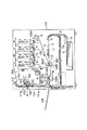
図8は、本発明に係る画像形成装置の一例の概略構成模型図である。本例の画像形成装置101はベルト状の中間転写体(中間転写ベルト)を用いたタンデム型の電子写真カラーレーザープリンタである。
Example 1
FIG. 8 is a schematic structural model diagram of an example of an image forming apparatus according to the present invention. The
この画像形成装置101は、即ち画像形成部Y、M、C、Kを備え、それぞれイエロー、マゼンタ、シアン、ブラックの各色のトナー画像を形成する所謂タンデム型である。この第1〜第4の4つの画像形成部Y、M、C、Kは、図8において、画像形成装置本体101内に左から右に順に並列配置されている。そして、画像形成装置101には、外部情報から所望の画像を読み取り、画像信号として、これらの画像形成部Y、M、C、Kに送信する不図示のリーダ部が備えられている。
The
各画像形成部Y、M、C、Kは、電子写真方式にて画像形成工程が実施される電子写真プロセス機構であり、それぞれ、図8においては矢印の反時計方向に所定のプロセススピードで回転駆動される第1の像担持体としての電子写真感光体ドラム(感光体ドラム)1、帯電装置2、レーザースキャナ3、現像装置4等の画像形成手段である電子写真プロセス機器を有しており、第1〜第4画像形成部Y、M、C、Kは、それぞれ感光体ドラム1上にフルカラー画像の色分解成分色である。イエロートナー像、マゼンタトナー像、シアントナー像、ブラックトナー像を所定の制御タイミングで形成する。 Each of the image forming units Y, M, C, and K is an electrophotographic process mechanism in which an image forming process is performed by an electrophotographic method, and each rotates at a predetermined process speed in the counterclockwise direction of an arrow in FIG. It has electrophotographic process equipment as image forming means such as an electrophotographic photosensitive drum (photosensitive drum) 1 as a first image carrier to be driven, a charging device 2, a laser scanner 3, and a developing device 4. The first to fourth image forming units Y, M, C, and K are color separation component colors of a full-color image on the photosensitive drum 1, respectively. A yellow toner image, a magenta toner image, a cyan toner image, and a black toner image are formed at a predetermined control timing.
各画像形成部Y、M、C、Kにて実施される画像形成工程は、感光体ドラム1の回転の過程で、その周囲にある上記画像形成手段によってなされる。先ず、帯電装置2によって、感光体ドラム1表面を均一に帯電する帯電工程が実施され、その後に、レーザースキャナ3によって、外部情報、ここでは、上記のリーダ部から送信されてきた画像情報に応じて、感光体ドラム1の表面を露光し、画像部の表面電位を変更することで静電像が形成される潜像形成工程(露光工程)が実施される。引き続いて、感光体ドラム1上に形成されたこの静電像を現像装置4によって現像し、可視像化された現像剤像(トナー像)とする現像工程が実施される。こうして、各画像形成部Y、M、C、Kにおいて、感光体ドラム1表面には、それぞれの色のトナー像が形成される。 The image forming process performed in each of the image forming units Y, M, C, and K is performed by the image forming unit around the photosensitive drum 1 in the process of rotation. First, a charging process for uniformly charging the surface of the photosensitive drum 1 is performed by the charging device 2, and then, according to external information, here, image information transmitted from the reader unit, by the laser scanner 3. Then, a latent image forming step (exposure step) is performed in which the surface of the photosensitive drum 1 is exposed and the surface potential of the image portion is changed to form an electrostatic image. Subsequently, the electrostatic image formed on the photoconductive drum 1 is developed by the developing device 4 to perform a developing process for forming a visualized developer image (toner image). Thus, in each of the image forming portions Y, M, C, and K, toner images of the respective colors are formed on the surface of the photosensitive drum 1.
こうした各画像形成部Y、M、C、Kにおける画像形成工程においては、画像形成装置制御手段としての制御基板104によって、画像形成装置101の各画像形成手段がシーケンス制御されることで、プリント動作が実行される。
In the image forming process in each of the image forming units Y, M, C, and K, each image forming unit of the
即ち、制御基板104は、プリントスタート信号に基づいて画像形成装置101の画像形成手段である電子写真プロセス機器各部を所定にシーケンス制御して動作させ、上記の画像形成工程により第1〜第4画像形成部Y、M、C、Kの各感光体ドラム1上に上記各色のトナー像を形成させる。
That is, the
これら各画像形成部Y、M、C、Kにおいて各感光体ドラム1表面に形成されたトナー像は、更なる画像形成工程における転写工程を経て記録媒体(メディア)Sに転写される。ここでは、中間転写方式を採用しているので、転写工程においては、感光体ドラム1から中間転写体への一次転写と、中間転写体に転写されたトナー像のメディアへの二次転写と、が実施される。 The toner image formed on the surface of each photosensitive drum 1 in each of these image forming portions Y, M, C, and K is transferred to a recording medium (media) S through a transfer process in a further image forming process. Here, since the intermediate transfer method is adopted, in the transfer process, primary transfer from the photosensitive drum 1 to the intermediate transfer member, secondary transfer of the toner image transferred to the intermediate transfer member to the medium, Is implemented.
転写工程を実行する転写手段について説明する。 The transfer means for executing the transfer process will be described.
中間転写体としては、第1〜第4の画像形成部Y、M、C、Kの下側に、第2の像担持体としての中間転写ベルト103が配設され、第1の画像形成部Y側に配設した第1の掛け回しローラ5と、第4の画像形成部K側に配設した第2の掛け回しローラ6と、第1の掛け回しローラ5の下方に配設した二次転写対向ローラ103Tの該3本の並行配列ローラ間に懸回張設してあり、第2の掛け回しローラ6を駆動ローラとして、矢印の時計方向に各画像形成部Y、M、C、Kの感光体ドラム1の回転速度と略同じ速度で回動駆動される。
As the intermediate transfer member, an
そして、第1と第2の掛け回しローラ5、6間のほぼ水平の中間転写ベルト103G部分を第1〜第4の画像形成部Y、M、C、Kの各感光体ドラム1の下向き面に対して、それぞれ一次転写ローラ7により当接させて各感光体ドラム1の下向き面と中間転写ベルト外面103Gとで一次転写ニップ部T1を形成させている。
The substantially horizontal
又、中間転写ベルト103の外側で二次転写対向ローラ103Tに対向する位置に二次転写装置105が配設してあり、二次転写ローラ105Tを二次転写対向ローラ103Tに対して中間転写ベルト103を介して所定の押圧力で当接させて、中間転写ベルト103と二次転写ローラ105Tとで二次転写ニップ部T2を形成させてある。
Further, a
二次転写ローラ105Tは、中間転写ベルト103の回動方向に順方向、図8においては矢印の反時計方向に中間転写ベルト103と略同じ速度で回転駆動される。
The
又、中間転写ベルトクリーナ8が、中間転写ベルト103の外側で第1の掛け回しローラ6に対向する位置に配設してあり、クリーニングブレード等のクリーニング部材を中間転写ベルト103の外面に接触させている。
An intermediate
転写工程においては、各画像形成部Y、M、C、Kにて形成されたイエロートナー像、マゼンタトナー像、シアントナー像、ブラックトナー像が、回動する中間転写ベルト103の外面に対して第1〜第4画像形成部Y、M、C、Kの各一次転写ニップ部T1において順次に重畳転写されることで、中間転写ベルト103の外面に未定着のフルカラートナー画像(鏡像)が合成形成される。その未定着のフルカラートナー画像は引続く中間転写ベルト103の回動で二次転写ニップ部T2へ移動していく。
In the transfer process, the yellow toner image, the magenta toner image, the cyan toner image, and the black toner image formed in each of the image forming units Y, M, C, and K are applied to the outer surface of the rotating
一方、給紙カセット9内に積載収容させた記録媒体(メディア)Sが給紙ローラ10の回転駆動で1枚分離給送され、シートパスa、bを通ってレジストローラ対11へ搬送される。メディアSは、中間転写ベルト103の外面に形成された未定着のフルカラートナーの先端部が二次転写ニップ部T2に到達したとき丁度メディアSの先端部も二次転写ニップ部T2に到達するようにレジストローラ対11でタイミング制御されて、二次転写ニップ部T2に導入される。
On the other hand, the recording medium (medium) S loaded and accommodated in the paper feed cassette 9 is separated and fed by the rotational drive of the
二次転写ニップ部T2に導入されたメディアSは、二次転写ニップ部T2で挟持搬送され、その挟持搬送の間に二次転写ローラ105Tに印加される所定の転写バイアスによって中間転写ベルト103側の未定着トナー像がメディアS上に順次に静電転写される。
The medium S introduced into the secondary transfer nip T2 is nipped and conveyed by the secondary transfer nip T2, and the
二次転写ニップ部T2を出たメディアSは中間転写ベルト103の面から曲率分離して定着装置102に搬送されていく。メディア分離後の中間転写ベルト103の面はクリーナ8で転写残りトナーの除去を受けて清浄面化されて繰り返して作像に供される。
The medium S that has exited the secondary transfer nip T2 is separated from the surface of the
定着装置102に搬送されたメディアSは、画像形成工程における定着工程を施される。
The medium S conveyed to the
定着装置102は、定着ローラ(加熱ローラ)102aと加圧ローラ102bとが圧接して構成される加熱・加圧定着装置である。加熱ローラ102aと加圧ローラ102bとの圧接部は、定着ニップ部Nとなり、ここにトナー像が転写されたメディアSが挟持搬送され、その際に定着工程が実施される。該両ローラ102a、102bは、矢印の方向に所定の速度で回転駆動される。又、定着ローラ102aは内蔵ヒータ102cにより加熱され、所定の定着温度に温調制御される。
The fixing
二次転写ニップ部T2側から定着装置102へ搬送されたメディアSは定着ニップ部Nに進入して定着ニップ部Nで挟持搬送され、定着工程にて、定着ニップ部Nにおいて加熱および加圧を受けることで未定着トナー画像が定着され、画像形成物として排出される。
The medium S conveyed from the secondary transfer nip T2 side to the
定着装置102を通過したメディアSは、ユーザの指定したフェイスダウントレイ(FDトレイ)112若しくはフェイスアップトレイ(FUトレイ)113に排紙される。
The medium S that has passed through the fixing
本実施例の画像形成装置においては、プリンタ101の動作として、上記に説明したような画像形成工程を実行して所望の画像形成物を得る通常プリントモードと、画像形成条件、例えば、帯電装置2における帯電条件や、レーザースキャナ3の露光強度や、現像装置4における現像バイアス、一次転写ローラ7に印加される一次転写バイアス等の様々な画像形成条件、ここでは濃度及び色度を適正にするための画像形成条件の制御を行うテストモードがある。
In the image forming apparatus of the present embodiment, as the operation of the
テストモードにおいては、画像形成装置の制御基板104において記憶された所定の信号であるテストパターン(パッチ)信号に基く光情報の照射により、テストパターン(パッチ)信号データに基づいて、感光体ドラム1a〜1d上に画像制御用静電潜像が形成されるようになっており、それを現像し、各画像形成部Y、M、C、Kから、転写工程を経てメディア上に定着されたテストパターンである画像制御用現像剤像(パッチ)を形成する。そして、各色の混パッチの画像濃度を、画像検知手段であるカラーセンサ120で測定し(以下、「パッチ検」と称す。)、画像の物性、通常は濃度や色度補正を行なう。
In the test mode, the photosensitive drum 1a is based on the test pattern (patch) signal data by irradiating optical information based on a test pattern (patch) signal which is a predetermined signal stored on the
この時、装置101上の図示しない操作パネル、又は装置101に接続されたパーソナルコンピュータ等でテストモードが指定された時、或いは図示しない制御部が環境の変化、装置各部の変動等の検知結果により、自動的に指定された時、テストモードが実行される。
At this time, when a test mode is designated by an operation panel (not shown) on the
ここでメディアS上に形成したパッチパターン301の一例を図9に示す。濃度または色度制御用パッチパターン301は、色再現域の中心であり、カラーバランスを取る上で非常に重要な色であるグレーの階調パッチパターンである。パッチパターン301は、色の濃い順にパターン302a、302b、302c、302d、302e、・・・を含む、ブラック(K)のみのグレー階調パッチ302と、色の濃い順にパターン303a、303b、303c、303d、303e・・・を含む、イエロー(Y)、マゼンダ(M)、シアン(C)を混色したプロセスグレー階調パッチ303と、で構成されている。そして、このパッチパターン301においては、パターン302aと303a、パターン302bと303b、パターン302cと303cといったように、標準の画像形成条件において色度が同じか又は最も近いブラック(K)のみのグレー階調パッチ302とプロセスグレー階調パッチ303とが対を成して並んでいる。
An example of the
このパッチ301の濃度及び色度を、定着部から排出部までのメディアSの搬送過程において、画像検知手段であるカラーセンサ120が、メディアS上に形成されたパッチ301のパッチ302aから順次検出し、検知結果を、制御基板104へフィードバックし、カラーセンサ120の出力値から、例えば、帯電装置2による帯電位、レーザスキャナ3の光強度、現像装置4が現像時に感光体ドラム1との間に印加する現像バイアス等の画像形成条件を調整し、カラーバランス補正データを生成する。これにより、トナー像の濃度又は色度制御を行ない、最適なカラーバランスのトナー像を形成することが可能となる。
The density and chromaticity of the
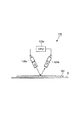
ここで使用される画像検知手段としてのカラーセンサ120は、図10に示すように、発光部120aと受光部120bとCPU120cとを有する光センサである。発光部120aから発生された照射光は、メディアS上のパッチ画像301によって反射され、その反射光を受光部120bによって受光する。受光した反射光の光量は、CPU120cを介して出力電圧に変換され、その出力値が装置の制御基板104にて、パッチ301の各部の濃度及び色度に換算される。
As shown in FIG. 10, the
ところで、従来では、カラーセンサの検知部を搬送中のメディア姿勢が安定せず、カラーセンサとの距離が、大きく変動(0〜3mm)してしまい、光学式のカラーセンサにより定着トナーパッチの濃度及び色度を、精度よく測定することは困難であるという問題があった。 By the way, conventionally, the posture of the medium during the conveyance of the detection unit of the color sensor is not stable, and the distance from the color sensor greatly fluctuates (0 to 3 mm), and the density of the fixing toner patch is caused by the optical color sensor. In addition, there is a problem that it is difficult to accurately measure the chromaticity.
そこで、本実施例においては、定着部102から排出部112までの搬送時のメディアSを、カラーセンサ120による測定時にセンサ120との距離、ここではセンサ120からの光がパッチ301まで光が移動する距離を固定する手段を設けることによって、この問題を解決した。
Therefore, in this embodiment, the medium S during conveyance from the fixing
本実施例では、メディアSの定着部102から排出部112までの搬送路(本明細書では「定着後搬送経路」と称す。)cに配置されるカラーセンサSによるメディアS上のパッチ検知を実施する測定位置Aにおいて、その定着後搬送経路cの両脇側に、搬送経路cにて搬送されるメディアSに対して平行面を有し、その平行面で互いに対向する2体の搬送ガイド121と123を有し、メディアSがそこを通過する時に、搬送ガイド121と123が近づいて、メディアSに接触して挟み込むことによって、メディアSの位置を安定させる。そして、搬送ガイド121は、このメディアSとの接触面に、メディアSには接触しないようにカラーセンサ120が備えられる。具体的には、ここでは、搬送ガイド121の搬送経路cに平行でメディアSと接触する面において、カラーセンサ120がその面から所定距離A1だけ凹んだ状態で保持される構成とされる。そのことによって、メディアS上のパッチ301形成面とカラーセンサ120との距離を常にA1とすることができる。
In the present embodiment, patch detection on the medium S by the color sensor S arranged in a conveyance path (referred to as “post-fixation conveyance path” in this specification) c from the fixing
この構成について、更に詳しく説明する。本実施例において、テストモード実行時には、FUトレイ112が選択され、メディアSは、定着装置102を通過した後、フィードローラ111a及び111bが備えられた定着後搬送経路である用紙搬送路cにて上方に進んで、排紙される。ここで、用紙搬送路cにおける用紙搬送方向で、上流側にフィードローラ111aが配置され、下流側に111bが配置されている。
This configuration will be described in more detail. In this embodiment, when the test mode is executed, the
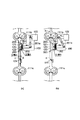
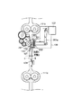
定着装置102から排紙トレイ112の間の用紙搬送路cで、用紙搬送路cに備えられたメディアSを挟持するフィードローラ111aと111bとの間に、図1(a)、(b)に詳しく示すように、(A)テストパターンであるパッチ301の濃度及び色度を測定するカラーセンサ120と、(B)カラーセンサ120を保持した第1の搬送ガイド121と、(C)その対向面に配設された搬送ガイド121の受け面となる第2の搬送ガイドとなる搬送受けガイド123と、(D)搬送ガイド121とメディアSとを当接させるバネ202と、(E)バネ202と搬送ガイド121を保持するガイドホルダ201と、(F)定着トナーパッチ測定時にガイドホルダ201を測定する位置Aへ移動させ、測定時以外は用紙搬送路cからガイドホルダ201を退避させた位置Bへ移動させる駆動源122(本実施例では、ソレノイドを用いた)と、を有する。
FIGS. 1A and 1B show a sheet conveyance path c between the fixing
ここで、測定位置Aにおいて、メディアSが上記(A)のカラーセンサ120を保持する上記(B)の搬送ガイド121と上記(C)の搬送受けガイド123に挟まれ、上記のように、搬送ガイド121のメディアSとの接触面に対してA1へ込んだ位置にカラーセンサ120が保持されているので、その時のセンサ120とパッチ301形成面との距離が常にA1となる。そして、上記(D)、(E)、(F)は、搬送ガイド121を測定位置Aに到来したメディアSに接触する、図1(a)に示す第1のポジションと、その位置から退避する、図1(b)に示す第2のポジションとに移動させる駆動機構であり、これらは、用紙搬送路cの搬送ガイド121側に設置されたカラーセンサ駆動機構収容部100に構成されている。
Here, at the measurement position A, the medium S is sandwiched between the conveyance guide 121 (B) holding the color sensor 120 (A) and the conveyance receiving guide 123 (C) and is conveyed as described above. Since the
カラーセンサ駆動機構収容部100は、搬送ガイド121の一面が用紙搬送路cを通過するメディアS表面に対して平行になるようにそれを保持する上記(E)のガイドフォルダ201を有し、連結アーム201aによって、カラーセンサ駆動機構収容部100の用紙搬送路cから離れた側に配置された(F)の駆動源122と連結しており、駆動源122の駆動が連結アーム201aを通してガイドフォルダ201に伝わり、搬送ガイド121を、搬送路cにて搬送されるメディアSに接離させる構成となる。尚、ここでは、搬送ガイド121の、メディアSに接触する第1ポジションとそれから退避する第2ポジションとの間の移動は、用紙搬送路cに対して垂直方向に近づけたり離したりする移動である。
The color sensor driving
搬送ガイド121は、上記のカラーセンサ駆動機構により搬送路cにてメディアSと接触し、その時搬送路cに設置された搬送受けガイド123がメディアS裏側から搬送ガイド121と当接する。搬送受けガイド123は、メディアSが通過する位置に対して裏側から接触するような位置に固定されている。搬送ガイド121が上記第1のポジションに到来した時には、搬送ガイド123と当接する。
The
又、保持部材121aは、搬送ガイド121を(E)のガイドホルダ201に保持させている。ガイドホルダ201は、搬送ガイド121の裏側に(D)のバネ202を接触させ、バネ202が用紙搬送路c側に搬送ガイド121を付勢するようになっている。
The holding member 121a holds the
次に、テストパターントナー像を定着したメディアSの用紙搬送路cにおける搬送過程と、上記の手段に測定位置が位置決めされるカラーセンサ120による測定時の状態を説明する。
Next, the conveyance process of the medium S on which the test pattern toner image is fixed in the sheet conveyance path c and the state at the time of measurement by the
1:メディアSがフィードローラ111aに到達し先端がフィードローラ111bに達するまで搬送される。
1: The medium S is conveyed until it reaches the
2:用紙搬送路cのメディアS搬送方向でフィードローラ111bより上流に配置された記録媒体検知手段であるメディアセンサ124の検知等のタイミングにより、メディアSの搬送状況を確認する。このタイミングとメディアセンサ123からフィードローラ111bまでの距離、メディアSの搬送速度より、メディアSの先端がフィードローラ111bに狭持されることを確認する。
2: The conveyance status of the medium S is confirmed based on the timing of detection by the
ここでは、上記の(A)〜(F)の手段によりカラーセンサ120がメディアSと対向する位置である測定位置Aからフィードローラ111bまでの距離は、メディアSの用紙先端からパッチ形成部先端までの距離より短く、用紙先端がフィードローラ111bに挟持された状態の時に、パッチ形成部先端がちょうど上記(B)の搬送ガイド121と対向する位置にある。
Here, the distance from the measurement position A where the
3:上記(F)の搬送ガイド121の駆動源122がONとなり、測定位置Aに移動した(E)のガイドホルダ201は、カラーセンサ駆動機構収容部100において、搬送ガイド121の用紙搬送路cへの出し入れ口に設けられた突起物であるストッパ203でメディアSとの距離が位置決めされ、図1(a)に示すように、搬送ガイド121は(D)のバネ202による付勢荷重P(本実施例は、P=70gfとした)でメディアSに押し付けられる。ここが第1のポジションである。
3: The
このとき、上記に説明したように、搬送ガイド121によりメディアSとカラーセンサ120の光学的検知距離A1(本実施例では、3mmとした)を一定に保つよう構成されている。そのため、メディアSと接する搬送ガイド121と搬送受けガイド123の表面は、平滑で摺動性の良い材質(本実施例では、POMを用いた)を使用している。
At this time, as described above, the
つまり、本発明の特徴としては、パッチが形成されたメディアSを定着装置102から排出部112まで搬送する間に、パッチ検が実行され、特に、そのパッチ検が光学的手段を用いるカラーセンサ120によって、それとメディアSとの距離が影響する測定を行う場合、検知位置Aにおいて、メディアSとセンサ120との距離A1が一定になるような手段、ここでは、搬送ガイド121のように、距離A1だけメディアSとの対向面から凹ませた位置にセンサ120を保持する部材をメディアSに圧接させる手段を設けたことである。
That is, as a feature of the present invention, patch detection is performed while the medium S on which the patch is formed is transported from the fixing
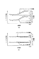
図2は、こうした対策前(図2(a))と対策後(図2(b))のメディアSとカラーセンサ120の距離に対するカラーセンサ120の出力値の関係を表す。対策前はカラーセンサ120とメディアSの距離を規制していないため、カラーセンサの出力値L1は大きく変動し、メディアSが搬送中のばたつきや波打つことで、メディアSとセンサ120との距離L2が最大約2mmであった。
FIG. 2 shows the relationship between the output value of the
しかし、対策後は搬送ガイド121と搬送受けガイド123でメディアSをはさみ、搬送するため、カラーセンサ120とメディアSの距離は規制され、L2は要求精度(本実施例では±0.2)内の約0.2mmに抑えることが出来る。それに伴い、対策前のカラーセンサ120の出力値L1に対し、対策後の出力値L1のばらつきを約1/10に安定させることが出来る。
However, since the media S is sandwiched and transported by the
つまり、メディア搬送路cに沿って搬送されている途中で、パッチ301を担持した側のメディアS表面とカラーセンサ120の距離A1を規制し、精度よく定着トナーパッチを測定できる。
In other words, while being transported along the media transport path c, the distance A1 between the surface of the medium S carrying the
ここで、カラーセンサ120によるパッチ301の測定後、用紙搬送路cからガイドホルダ201を退避させ、図1(b)に示す第2のポジションBへ移動させる。このように、搬送ガイド121を測定位置Aから退避させることで、通常プリントモード時、搬送ガイド121にメディアSが衝突することでジャムの発生することを防止し、搬送ガイド121とメディアSのこすれによるカラーセンサ120部への紙紛付着を防止することと、定着後のメディアSと常に接触することで、カラーセンサ120の温度が上昇することによるカラーセンサ120の測定誤差を抑えることができる、又、印字面と接触することで画像不良の発生を防ぐことができ、高品位なカラー原稿を作成することができる。
Here, after the
更には、本実施例の場合、用紙搬送路cにおいて測定位置Aの部分よりメディアSの搬送方向下流側にフィードローラ111bを有し、用紙搬送路cにおいてメディアSがあるかないかを検知する記録媒体検知手段であるメディアセンサ124を有し、その検知信号により、メディアSの用紙先端がフィードローラ111bに狭持されるタイミングで、搬送ガイド121をメディアS表面に接触させる第1のポジションに移動し、メディアSの後端が搬送ガイド121との対向部分を通過したタイミングで、測定位置Aから離間させる第2のポジションへと移動させることで、メディアSの搬送不良を防止するだけでなく、より多くのテストパターンのパッチを高精度に測定することが可能となる。
Further, in the case of the present embodiment, the recording roller C has a
尚、上記の(A)〜(F)に記載したパッチ検知位置を安定させる機構は、これに限るものではなく、メディアの定着部から排出部へ向かう搬送過程で、2つの搬送ガイドによってメディアを挟んで、そのどちらかの搬送ガイドによってカラーセンサが、搬送ガイドに挟まれたメディア表面との距離を一定にして保持される構成であればよく、カラーセンサを保持する方の第1の搬送ガイドが、搬送中のメディアに接触したり離間したりすることが可能であればよい。その離接動作における第1の搬送ガイドの移動方向は、本実施例のような定着後搬送経路に垂直方向と限定されるものではなく、又、駆動方法も、本実施例にて説明したようなものと限定されるものでない。 Note that the mechanism for stabilizing the patch detection position described in (A) to (F) above is not limited to this, and in the process of transporting the medium from the fixing unit to the discharge unit, the medium is guided by two transport guides. The first conveyance guide that holds the color sensor may be used as long as the color sensor is held at a constant distance from the media surface sandwiched between the conveyance guides by either conveyance guide. However, what is necessary is just to be able to contact or separate the medium being conveyed. The moving direction of the first transport guide in the separation / contact operation is not limited to the direction perpendicular to the post-fixing transport path as in this embodiment, and the driving method is also described in this embodiment. It is not limited to anything.
そして、パッチも、図3に示したようなパッチ301のパターンに限定されず、単色画像形成装置における場合や濃度検知等は、ベタ画像にてなされる場合もある。
Further, the patch is not limited to the pattern of the
又、画像形成装置の構成に関しては、図8に示すものに限定されず、定着後搬送経路も上方へ向かうものでなくともよい。そして、中間転写体を設けず、感光体ドラムから直接記録媒体にトナー像を転写する構成でもよく、タンデム方式でなくともよく、感光体ドラムが1個のものでも良い。そして、静電記録方式のものや単色画像形成装置においても本発明は適用できる。 Further, the configuration of the image forming apparatus is not limited to that shown in FIG. 8, and the post-fixing conveyance path may not be directed upward. In addition, the toner image may be directly transferred from the photosensitive drum to the recording medium without providing the intermediate transfer member, the tandem method may be used, and the single photosensitive drum may be used. The present invention can also be applied to an electrostatic recording type and a monochromatic image forming apparatus.
以上に説明した画像形成装置の構成部品の寸法、材質、形状、及びその相対位置などは、特に特定的な記載がない限りは、この発明の範囲をそれらのみに限定する趣旨のものではない。 The dimensions, materials, shapes, and relative positions of the components of the image forming apparatus described above are not intended to limit the scope of the present invention only to those unless otherwise specified.
実施例2
本実施例における画像形成装置の全体構成及び動作は実施例1のものとほぼ同様であるので、同じ符号を用い、これらの構造要素については説明を省略する。又、メディアSの定着後搬送経路である用紙搬送路cの配置も実施例1に説明したものと同様とする。
Example 2
Since the overall configuration and operation of the image forming apparatus in the present embodiment are substantially the same as those in the first embodiment, the same reference numerals are used and description of these structural elements is omitted. The arrangement of the sheet conveyance path c, which is the conveyance path after fixing of the medium S, is the same as that described in the first embodiment.
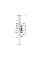
本実施例で実施例1と異なるのは、図3に示すように、カラーセンサ120を保持した搬送ガイド121に、カラーセンサ120とメディアSとの距離A1を一定(本実施例では、3mmとした)に保ち、メディアSの搬送性を向上させるために規制ローラ部材(ガイドローラ)401を配設したことを特徴とするものである。
As shown in FIG. 3, the present embodiment is different from the first embodiment in that the distance A1 between the
ガイドローラ401は、カラーセンサ120の作動時に投受光される光の通路の近傍に設置される。特に、測定位置AにおけるメディアS搬送方向に交差する方向の断面図である図4に示すように、カラーセンサ120、即ちカラーセンサ120の作動時に投受光される光の通路を挟むようメディアS搬送方向の直交方向略直線上に配置されることが好適である。そして、テストパターン測定時には、ガイドローラ401が搬送受けガイド123、及びバネ202によりメディアSに対し荷重P(本実施例では、P=70gfとした)で加圧することで、メディアSの搬送のばたつきや波打ちを要求精度内(本実施例では±0.2mm)に抑えることができ、テストパターンのパッチ301を高精度に測定することが可能である。
The
又、搬送ガイド121にガイドローラ401を有することで、搬送中のメディアSとの接触抵抗を低減することで、メディア先端がフィードローラ111bに到達してから搬送ガイドを位置Aに移動させ、メディアSを引っ張って搬送しなくても、ジャム等搬送不良の発生を抑えることができるので、メディアSがフィードローラ111aにより搬送され、メディアSの搬送状況を確認するメディアセンサ124の検知等のタイミングにより、メディアS先端がカラーセンサ120の位置まで到達したタイミングで、搬送ガイド121を位置Aへ移動させることが出来る。実施例1では、メディアSがフィードローラ111bに到達した後、テストパターンのパッチパターン301を測定していたのに対し、本実施例では、メディアSの搬送方向の先端からテストパターンのパッチパターン301を測定することができる。
Further, by having the
これにより、一度に多くのパッチパターン301を測定することが可能であり、より多くの測定情報を基にカラーバランス補正データを生成することができ、トナー画像の濃度又は色度制御を行なうことで、最適なカラーバランスのトナー画像を形成することが可能であり、高品位なカラー原稿を作成することができる。
As a result, it is possible to measure a large number of
実施例3
本実施例における画像形成装置の全体構成及び動作は実施例1のものとほぼ同様であるので、同じ符号を用い、これらの構造要素については説明を省略する。又、メディアSの定着後搬送経路である用紙搬送路cの配置も実施例1に説明したものと同様とする。
Example 3
Since the overall configuration and operation of the image forming apparatus in the present embodiment are substantially the same as those in the first embodiment, the same reference numerals are used and description of these structural elements is omitted. The arrangement of the sheet conveyance path c, which is the conveyance path after fixing of the medium S, is the same as that described in the first embodiment.
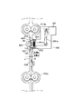
本実施例で実施例1、実施例2と異なるのは、図5、図6に示すように、カラーセンサ120を保持した搬送ガイド121に、カラーセンサ120とメディアSとの距離A1を一定(本実施例では、3mmとした)に保ち、メディアSの搬送性を向上させるために配設したガイドローラ401と対向する位置に、対向ガイドローラ601を配設したことを特徴としたものである。ここで対向ガイドローラ601は、巾広であり、図6に示すように、2つのローラ401の両方の対向ローラとなる。
The present embodiment differs from the first and second embodiments in that the distance A1 between the
テストパターン測定時、搬送ガイド121を位置Aに移動させ、対向ガイドローラ601とガイドローラ401が、バネ202によりメディアSに対し荷重P(本実施例では、P=70gfとした)で狭持することで、メディアSの搬送のばたつきや波打ちを要求精度内(本実施例では±0.2mm)に抑えることができ、テストパターンのパッチ301を高精度に測定することが可能である。
At the time of measuring the test pattern, the
又、実施例2同様に、ガイドローラ401を有することで、メディアSがフィードローラ111aにより搬送され、メディアの搬送状況を確認するメディアセンサ124の検知等のタイミングにより、メディアS先端がカラーセンサ120の位置まで到達したタイミングで、搬送ガイド121を第1のポジションAへ移動させることができる。更に、対向ガイドローラ601を有することで、搬送ガイドローラ601とガイドローラ401により狭持搬送されることで、搬送ガイドローラ601とガイドローラ401のニップ部Nrにおいて、メディアSの搬送中の抵抗を低減させ、メディアSの搬送不良の発生を抑制できる。
Further, similarly to the second embodiment, by having the
これにより、一度に多くのパッチパターン301を安定して測定することが可能であり、より多くの測定情報を基にカラーバランス補正データを生成することができ、トナー画像の濃度または色度制御を行なうことで、最適なカラーバランスのトナー画像を形成することが可能となり、高品位なカラー原稿を作成することができる。
As a result, it is possible to stably measure a large number of
実施例4
本実施例における画像形成装置の全体構成及び動作は実施例1のものとほぼ同様であるので、同じ符号を用い、これらの構造要素については説明を省略する。又、メディアSの定着後搬送経路である用紙搬送路cの配置も実施例1に説明したものと同様とする。
Example 4
Since the overall configuration and operation of the image forming apparatus in the present embodiment are substantially the same as those in the first embodiment, the same reference numerals are used and description of these structural elements is omitted. The arrangement of the sheet conveyance path c, which is the conveyance path after fixing of the medium S, is the same as that described in the first embodiment.
本実施例で実施例1〜3と異なるのは、図7に示すように、カラーセンサ120を保持した搬送ガイド121に、カラーセンサ120とメディアSとの距離を一定(本実施例では、3mmとした)に保ち、メディアSの搬送性を向上させるために配設したガイドローラ401と対向する位置に配設した搬送ガイドローラ701が、メディアSを搬送するフィードローラ111bと同期した搬送速度で駆動することを特徴とするものである。
This embodiment differs from the first to third embodiments in that the distance between the
テストパターン測定時、搬送ガイド121を位置Aに移動させ、搬送ガイドローラ701とガイドローラ401が、バネ202によりメディアSに対し荷重P(本実施例では、P=70gfとした)で狭持することで、メディアSの搬送のばたつきや波打ちを要求精度内(本実施例では±0.2mm)に抑えることができ、テストパターンのパッチ301を高精度に測定することが可能である。更に、搬送ガイドローラ701を有することで、メディアSの搬送状況を確認するメディアセンサ124の検知等のタイミングにより、メディアS先端がカラーセンサ120の位置まで到達する前に、搬送ガイド121を位置Aへ移動させ、メディアSの搬送方向の先端からテストパターンのパッチ301を測定できる。これは、メディアSの先端がカラーセンサ120の位置まで搬送されると、搬送ガイドローラ701とガイドローラ401により狭持搬送されることで、搬送ガイドローラ701とガイドローラ401のニップ部Nrにおいて、メディアSに対する搬送中の抵抗を低減させ、安定した測定を行なうことが出来る。
When measuring the test pattern, the
これにより、一度により多くのパッチパターン301を安定して測定することが可能であり、薄紙といった搬送不良の発生しやすいメディアでも安定して搬送することが可能であり、より多くの測定情報を基にカラーバランス補正データを生成することができ、トナー画像の濃度または色度制御を行なうことで、最適なカラーバランスのトナー画像を形成することが可能となり、高品位なカラー原稿を作成することができる。
Accordingly, it is possible to stably measure
つまり、ガイドローラと対向した位置に対向ガイドローラを配設することでメディアを狭持し、メディアの搬送のばたつきや波打ちを抑えることで、テストパターンのパッチを高精度に測定できる。 That is, it is possible to measure the patch of the test pattern with high accuracy by sandwiching the medium by disposing the counter guide roller at a position facing the guide roller and suppressing fluttering and undulation of the medium.
尚、本実施例内において、搬送ガイド121もしくはガイドローラ401を、メディアSに対し荷重をかけ当接させた状態でパッチパターン301を測定させていたが、メディアSの種類等に応じて、荷重をかけない、もしくは当接させない位置においてパッチパターン301を測定することも可能である。
In the present embodiment, the
102 定着装置(定着手段)
111a、111b フィードローラ
112 フェイスダウントレイ(排出部)
120 カラーセンサ(画像検知手段)
121 搬送ガイド(第1の搬送ガイド)
122 駆動源
123 搬送受けガイド(第2の搬送ガイド)
124 メディアセンサ(記録媒体検知手段)
201 ガイドホルダ
202 ばね
203 ストッパ
301 パッチパターン(画像制御用現像剤像)
401 ガイドローラ(規制ローラ部材)
601 対向ガイドローラ
701 搬送ガイドローラ
S メディア(記録媒体)
102 Fixing device (fixing means)
111a,
120 color sensor (image detection means)
121 Transport guide (first transport guide)
122
124 media sensor (recording medium detection means)
201
401 Guide roller (regulating roller member)
601
Claims (14)
所定の条件により前記未定着画像として画像制御用現像剤像が形成され、該画像制御用現像剤像は前記定着手段にて前記記録媒体上に定着され、その後に、該記録媒体が前記定着手段から搬送される定着後搬送経路にて、前記画像検知手段が前記画像制御用現像剤像に対して前記画像の物性を測定する画像形成装置において、
更に、前記画像検知手段を保持し、前記定着後搬送経路にて、該記録媒体に定着された前記画像制御用現像剤像を担持した表面と前記画像検知手段との距離を規制する第1の搬送ガイドと、
該第1の搬送ガイドを、前記定着後搬送経路にて、前記記録媒体に対して近接及び離間させる駆動源と、
前記第1の搬送ガイドの前記定着後搬送経路における対向面に対して平行面を有し、該平行面で前記第1の搬送ガイドと当接する第2の搬送ガイドと、を備えることを特徴とする画像形成装置。 Means for forming an unfixed image on a recording medium; fixing means for fixing the unfixed image on the recording medium; and image detecting means for optically measuring physical properties of the image fixed on the recording medium; An image forming apparatus comprising:
An image control developer image is formed as the unfixed image under a predetermined condition. The image control developer image is fixed on the recording medium by the fixing unit, and then the recording medium is fixed to the fixing unit. In the image forming apparatus in which the image detection unit measures the physical properties of the image with respect to the image control developer image in a post-fixing conveyance path conveyed from
Furthermore, the image detecting means is held, and a distance between the image detecting means and the surface carrying the image controlling developer image fixed on the recording medium is regulated in the post-fixing conveyance path. A transport guide;
A drive source for causing the first conveyance guide to approach and separate from the recording medium in the post-fixing conveyance path;
A second conveyance guide having a parallel surface with respect to a facing surface of the first conveyance guide in the conveyance path after fixing, and contacting the first conveyance guide on the parallel surface. Image forming apparatus.
Priority Applications (1)
| Application Number | Priority Date | Filing Date | Title |
|---|---|---|---|
| JP2004106663A JP4724374B2 (en) | 2004-03-31 | 2004-03-31 | Image forming apparatus |
Applications Claiming Priority (1)
| Application Number | Priority Date | Filing Date | Title |
|---|---|---|---|
| JP2004106663A JP4724374B2 (en) | 2004-03-31 | 2004-03-31 | Image forming apparatus |
Publications (3)
| Publication Number | Publication Date |
|---|---|
| JP2005292431A true JP2005292431A (en) | 2005-10-20 |
| JP2005292431A5 JP2005292431A5 (en) | 2007-05-17 |
| JP4724374B2 JP4724374B2 (en) | 2011-07-13 |
Family
ID=35325423
Family Applications (1)
| Application Number | Title | Priority Date | Filing Date |
|---|---|---|---|
| JP2004106663A Expired - Lifetime JP4724374B2 (en) | 2004-03-31 | 2004-03-31 | Image forming apparatus |
Country Status (1)
| Country | Link |
|---|---|
| JP (1) | JP4724374B2 (en) |
Cited By (4)
| Publication number | Priority date | Publication date | Assignee | Title |
|---|---|---|---|---|
| JP2010169958A (en) * | 2009-01-23 | 2010-08-05 | Fuji Xerox Co Ltd | Image forming apparatus |
| US9310741B2 (en) | 2013-01-16 | 2016-04-12 | Canon Kabushiki Kaisha | Image forming apparatus and colorimetric apparatus |
| JP2016189577A (en) * | 2015-03-30 | 2016-11-04 | コニカミノルタ株式会社 | Image reading device, image forming apparatus, and image forming system |
| JP2017156434A (en) * | 2016-02-29 | 2017-09-07 | キヤノン株式会社 | Image forming apparatus and method for controlling image forming apparatus |
Citations (5)
| Publication number | Priority date | Publication date | Assignee | Title |
|---|---|---|---|---|
| JPH10300584A (en) * | 1997-03-10 | 1998-11-13 | Xeikon Nv | Reflectometer and method for monitoring print quality of printed document |
| JP2938929B2 (en) * | 1990-05-11 | 1999-08-25 | キヤノン株式会社 | Image forming device |
| JPH11316476A (en) * | 1998-05-01 | 1999-11-16 | Fuji Xerox Co Ltd | Image forming device |
| JP2001209217A (en) * | 1999-11-19 | 2001-08-03 | Fuji Xerox Co Ltd | Image forming device and patch density measuring device |
| JP2003162198A (en) * | 2001-11-28 | 2003-06-06 | Canon Inc | Image forming device |
-
2004
- 2004-03-31 JP JP2004106663A patent/JP4724374B2/en not_active Expired - Lifetime
Patent Citations (5)
| Publication number | Priority date | Publication date | Assignee | Title |
|---|---|---|---|---|
| JP2938929B2 (en) * | 1990-05-11 | 1999-08-25 | キヤノン株式会社 | Image forming device |
| JPH10300584A (en) * | 1997-03-10 | 1998-11-13 | Xeikon Nv | Reflectometer and method for monitoring print quality of printed document |
| JPH11316476A (en) * | 1998-05-01 | 1999-11-16 | Fuji Xerox Co Ltd | Image forming device |
| JP2001209217A (en) * | 1999-11-19 | 2001-08-03 | Fuji Xerox Co Ltd | Image forming device and patch density measuring device |
| JP2003162198A (en) * | 2001-11-28 | 2003-06-06 | Canon Inc | Image forming device |
Cited By (4)
| Publication number | Priority date | Publication date | Assignee | Title |
|---|---|---|---|---|
| JP2010169958A (en) * | 2009-01-23 | 2010-08-05 | Fuji Xerox Co Ltd | Image forming apparatus |
| US9310741B2 (en) | 2013-01-16 | 2016-04-12 | Canon Kabushiki Kaisha | Image forming apparatus and colorimetric apparatus |
| JP2016189577A (en) * | 2015-03-30 | 2016-11-04 | コニカミノルタ株式会社 | Image reading device, image forming apparatus, and image forming system |
| JP2017156434A (en) * | 2016-02-29 | 2017-09-07 | キヤノン株式会社 | Image forming apparatus and method for controlling image forming apparatus |
Also Published As
| Publication number | Publication date |
|---|---|
| JP4724374B2 (en) | 2011-07-13 |
Similar Documents
| Publication | Publication Date | Title |
|---|---|---|
| US7792446B2 (en) | Image heating apparatus with controller for changing time duration of pressing belt with fixing member | |
| JP5279600B2 (en) | Sheet conveying apparatus and image forming apparatus | |
| US20080025742A1 (en) | Image forming apparatus and image forming method | |
| JP5790046B2 (en) | Image forming apparatus and image density control method | |
| JP2021195208A (en) | Sheet carrier, image reader and image forming apparatus | |
| JP2008050166A (en) | Image forming apparatus | |
| JP4347208B2 (en) | Image forming apparatus and control value setting method thereof | |
| JP4724374B2 (en) | Image forming apparatus | |
| JP2012208511A (en) | Image forming apparatus | |
| JP6226655B2 (en) | Image forming apparatus | |
| JP5430366B2 (en) | Transfer device and image forming apparatus | |
| JP5864997B2 (en) | Recording material discrimination apparatus and image forming apparatus | |
| JP4447975B2 (en) | Color image forming apparatus | |
| JP2003057908A (en) | Image forming device | |
| JP2016057455A (en) | Image forming apparatus | |
| JP2007286383A (en) | Transfer device and image forming apparatus using the same | |
| JP4387883B2 (en) | Image forming apparatus | |
| JP4717723B2 (en) | Recording material detector | |
| JP2006011205A (en) | Electrophotographic image forming apparatus | |
| JP2005154096A (en) | Recording material detection mechanism and image forming apparatus using the same | |
| JP7512625B2 (en) | Image forming apparatus and image forming method | |
| JP2017021114A (en) | Image forming apparatus | |
| JP2006143420A (en) | Color image forming apparatus | |
| JP2006151635A (en) | Image forming apparatus and sheet conveying apparatus | |
| JP6039788B2 (en) | Recording material detection apparatus and image forming apparatus |
Legal Events
| Date | Code | Title | Description |
|---|---|---|---|
| A521 | Written amendment |
Free format text: JAPANESE INTERMEDIATE CODE: A523 Effective date: 20070328 |
|
| A621 | Written request for application examination |
Free format text: JAPANESE INTERMEDIATE CODE: A621 Effective date: 20070328 |
|
| A131 | Notification of reasons for refusal |
Free format text: JAPANESE INTERMEDIATE CODE: A131 Effective date: 20090714 |
|
| A521 | Written amendment |
Free format text: JAPANESE INTERMEDIATE CODE: A523 Effective date: 20090914 |
|
| A02 | Decision of refusal |
Free format text: JAPANESE INTERMEDIATE CODE: A02 Effective date: 20091110 |
|
| A521 | Written amendment |
Free format text: JAPANESE INTERMEDIATE CODE: A523 Effective date: 20100209 |
|
| A911 | Transfer of reconsideration by examiner before appeal (zenchi) |
Free format text: JAPANESE INTERMEDIATE CODE: A911 Effective date: 20100318 |
|
| A912 | Removal of reconsideration by examiner before appeal (zenchi) |
Free format text: JAPANESE INTERMEDIATE CODE: A912 Effective date: 20100423 |
|
| A01 | Written decision to grant a patent or to grant a registration (utility model) |
Free format text: JAPANESE INTERMEDIATE CODE: A01 |
|
| A61 | First payment of annual fees (during grant procedure) |
Free format text: JAPANESE INTERMEDIATE CODE: A61 Effective date: 20110411 |
|
| FPAY | Renewal fee payment (event date is renewal date of database) |
Free format text: PAYMENT UNTIL: 20140415 Year of fee payment: 3 |
|
| R150 | Certificate of patent or registration of utility model |
Ref document number: 4724374 Country of ref document: JP Free format text: JAPANESE INTERMEDIATE CODE: R150 Free format text: JAPANESE INTERMEDIATE CODE: R150 |