JP2005292591A - Display device and camera - Google Patents
Display device and camera Download PDFInfo
- Publication number
- JP2005292591A JP2005292591A JP2004109234A JP2004109234A JP2005292591A JP 2005292591 A JP2005292591 A JP 2005292591A JP 2004109234 A JP2004109234 A JP 2004109234A JP 2004109234 A JP2004109234 A JP 2004109234A JP 2005292591 A JP2005292591 A JP 2005292591A
- Authority
- JP
- Japan
- Prior art keywords
- display
- light
- camera
- denotes
- lcd
- Prior art date
- Legal status (The legal status is an assumption and is not a legal conclusion. Google has not performed a legal analysis and makes no representation as to the accuracy of the status listed.)
- Pending
Links
Images
Landscapes
- Viewfinders (AREA)
- Indication In Cameras, And Counting Of Exposures (AREA)
- Liquid Crystal (AREA)
- Planar Illumination Modules (AREA)
Abstract
【課題】品位を損ねることなく、ユーザーにとって自然に感じることができる表示装置を提供すること。
【解決手段】光を透過させる表示パターン(43〜48)を有する表示素子であるLCD57と、発光素子であるLED52と、該LCD57の背面側に配置され、LED52からの光をLCD57側に反射する複数の反射部55bが形成されたライトガイド55とが設けられている。
そして、ライトガイド55は、LCD52のうち特定の表示パターン(48)以外の表示パターン(43〜47)に対応する第1の領域と、特定の表示パターン(48)に対応する第2の領域とを有し、第2の領域における反射部55eの形成密度が第1の領域のうち該第2の領域に近接する部分の反射部55dの形成密度より高くする
【選択図】 図5
To provide a display device that can be naturally felt by a user without losing quality.
An LCD 57 that is a display element having a display pattern (43 to 48) that transmits light, an LED 52 that is a light emitting element, and a back side of the LCD 57, and reflects light from the LED 52 toward the LCD 57 side. A light guide 55 having a plurality of reflecting portions 55b is provided.
The light guide 55 includes a first area corresponding to the display patterns (43 to 47) other than the specific display pattern (48) in the LCD 52, and a second area corresponding to the specific display pattern (48). And the formation density of the reflection portions 55e in the second region is higher than the formation density of the reflection portions 55d in the portion close to the second region in the first region.
Description
本発明は、透過型LCDと照明源とを有する表示装置に関する。 The present invention relates to a display device having a transmissive LCD and an illumination source.
従来、透過、もしくは半透過型LCDを暗所においても視認できるよう、バックライトと共に構成された表示装置が広く製品化されている。この表示装置は照明源にLEDを使用し、アクリル製の導光板を介してLCDの全面を照明することで、低コスト・高品位を実現することができ、現在の一般的な手法として用いられている。 Conventionally, display devices configured with a backlight so that a transmissive or transflective LCD can be viewed in a dark place have been widely commercialized. This display device uses an LED as an illumination source, and can illuminate the entire surface of the LCD via an acrylic light guide plate, thereby realizing low cost and high quality. ing.
具体的にはLCDの背面に導光板を置き、導光板の横からLEDの光を入光させる。この導光板にはLCDと反対側の面にマット処理を施してLEDからの光束をLCD側に反射する機能を持っている。 Specifically, a light guide plate is placed on the back of the LCD, and LED light is incident from the side of the light guide plate. This light guide plate has a function of performing a matting process on the surface opposite to the LCD to reflect the light flux from the LED to the LCD side.
しかし、マット面を全面に均一に設けると、LEDからの距離が近ければ明るく、遠ければ暗くなり、明るさにムラが生じてしまう。これを防ぐために、LEDの近くはマット面に形成するドット部を疎に、遠くは該ドット部を密とすることでLCD上での明るさがムラ無く高品位に見えるように工夫している。これらをファインダ表示装置に適応した例を、具体的な構成を図7、図8を用いて説明する。 However, if the matte surface is uniformly provided on the entire surface, the light becomes brighter if the distance from the LED is shorter, and darker if the distance is farther, resulting in unevenness in brightness. In order to prevent this, the dots formed on the matte surface are sparse near the LEDs, and the dots are densely arranged far away so that the brightness on the LCD looks high-quality without unevenness. . An example in which these are applied to a finder display device will be described with reference to FIGS. 7 and 8. FIG.
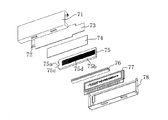
図7はファインダLCDユニットの構成を示した背面からの展開斜視図である。以下、組立順にファインダLCDユニットの構成を説明する。 FIG. 7 is a developed perspective view from the back showing the configuration of the finder LCD unit. Hereinafter, the configuration of the finder LCD unit will be described in the order of assembly.
71はファインダLCDホルダである。まず、ファインダLED72を実装したファインダFPC73を落とし込み、さらに反射シート74、ライトガイド75を落とし込む。ファインダLCDホルダ71とライトガイド75で形成される空隙部に異方性導電ゴム76を挿入する。これらの上にファインダLCD77を載設し、押さえ板78で押さえ込む。この時、異方性導電ゴム76は圧縮されて導電性を生じ、ファインダFPC73とファインダLCD77とを電気的に接続する。
そして、不図示のカメラ制御回路によってファインダLCD77を駆動するべくファインダFPC73に通電するとファインダLCD77は所定のマークが点灯、もしくは点滅する。
When a finder FPC 73 is energized to drive the
同時にカメラ制御回路によってファインダLED72を駆動するべくファインダFPC73に通電するとファインダLED72が点灯し、その光はライトガイド75の端面75cを照明する。端面75cから入光した光は裏面に形成されたマット面によって反射されてファインダLCD77側に射出される。また、マット面を透過してしまった光は反射シート74によって反射されて再度ライトガイド75の中に戻される。このようにしてファインダLCD77のバックライトとして機能する。
At the same time, when the viewfinder FPC 73 is energized to drive the
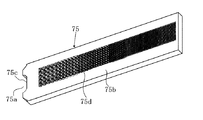
図8はライトガイド75を拡大した背面斜視図である。75aは入射部であり、ファインダLED72を覆うように形成され、射出してきた光を漏らさないようにしている。75bはマット面であり、光を照射することが必要なエリアにのみドット部75dの繰り返しによるマット処理が施されている。入射部75aから入光した光は拡散してしまうので、入射部75aから離れるに従って光密度は小さくなり、反射光の明るさも低くなっていく。しかし、それではファインダ表示の見た目の品位が悪くなってしまう。そこで、それを補正するために入射部75aから徐々に離れていくに従ってドット部75dの密度を増してファインダでの見た目の明るさが均一になるようにしている。
FIG. 8 is an enlarged rear perspective view of the
また、表示部の輝度を増すために、導光板の光射出面のうち、LCD表示文字に対応する部分を残して反射面を設け、文字部以外に向かった光を再利用することで輝度を増す工夫を施されている(特許文献1参照)。
しかしながら、上記従来例において、マットによる反射面の形成は、マット(ドット)が粗く、表示面積が大きい表示パターンの場合、ドットの粒状感が表示として見えてしまい、品位を損ねてしまう。しかし、該ドットを細かくするためには限界があり、細かくしすぎると導光板の成型管理が難しくなって加工コストが高くなる。 However, in the above-described conventional example, the formation of the reflective surface by the mat causes the graininess of the dots to appear as a display in the case of a display pattern having a large mat (dot) and a large display area, which impairs the quality. However, there is a limit to make the dots finer, and if the dots are made too fine, it becomes difficult to control the molding of the light guide plate, and the processing cost increases.
また、文字部以外に反射面を設けて効率を上げる手法も、情報量を増すために表示間隔を狭めていくと、あまり効率をあげることができなくなってしまう。 In addition, the method of increasing the efficiency by providing a reflective surface other than the character portion cannot increase the efficiency much if the display interval is narrowed to increase the amount of information.
特に、カメラのファインダ内表示においては、狭いエリアの表示をファインダ接眼光学系によって拡大表示するために、上記のような補正(入射部から徐々に離れていくに従ってドット密度を増やし、ファインダでの見た目の明るさが均一になるようにする補正)をすると、入射部に近いところにレイアウトされている表示面積の大きい表示パターンは、該ドットが透けて見えてしまう課題を有する。 Especially in the viewfinder display of the camera, in order to enlarge the display of a narrow area with the viewfinder eyepiece optical system, the correction as described above (the dot density is increased as the distance from the incident part is gradually increased, and If the correction is performed so that the brightness of the image becomes uniform, a display pattern with a large display area laid out near the incident portion has a problem that the dots can be seen through.
また、表示パターンの機能によってはユーザーに認知させるために他の表示に対して明るく表示される必要がある。 Further, depending on the function of the display pattern, it is necessary to display it brightly with respect to other displays so that the user can recognize it.
そこで本発明は、品位を損ねることなく、ユーザーにとって自然に感じることができる表示装置を提供することを目的とする。 SUMMARY OF THE INVENTION An object of the present invention is to provide a display device that can be naturally felt by a user without deteriorating the quality.
本発明の表示装置は、光を透過させる表示パターンを有する表示素子と、発光素子と、表示素子の背面側に配置され、発光素子からの光を表示素子側に反射する複数の反射部が形成されたライトガイドとを有する。 The display device of the present invention includes a display element having a display pattern that transmits light, a light emitting element, and a plurality of reflecting portions that are arranged on the back side of the display element and reflect light from the light emitting element to the display element side. Light guide.
そして、ライトガイドは発光素子のうち特定の表示パターン以外の表示パターンに対応する第1の領域と、特定の表示パターンに対応する第2の領域とを有し、第2の領域における反射部の形成密度が第1の領域のうち該第2の領域に近接する部分の反射部の形成密度より高いことを特徴とする。 The light guide has a first region corresponding to a display pattern other than the specific display pattern among the light emitting elements, and a second region corresponding to the specific display pattern, and the light guide has a reflection portion in the second region. The formation density is higher than the formation density of the reflective portion in the portion of the first region adjacent to the second region.
本発明によれば、第2の領域における反射部の形成密度を近接する第1の領域に形成された反射部の形成密度よりも高く構成しているため、第1の領域に対応して設けられる他の表示パターンよりも第2の領域に対応する特定の表示パターンを明るく表示することが可能となる。 According to the present invention, since the formation density of the reflection part in the second region is higher than the formation density of the reflection part formed in the adjacent first area, the reflection density is provided corresponding to the first area. The specific display pattern corresponding to the second area can be displayed brighter than the other display patterns.
さらに、第2の領域における反射部の形成密度が高いことから該特定の表示パターンを通して該反射部が見えることによる不自然さを低減させることが可能となる。よって、品位の高い表示パターンの表示が可能な表示装置を実現する。 Furthermore, since the formation density of the reflection parts in the second region is high, it is possible to reduce unnaturalness due to the reflection parts being visible through the specific display pattern. Therefore, a display device capable of displaying a high-quality display pattern is realized.
以下に本発明の実施例について説明する。 Examples of the present invention will be described below.
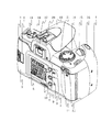
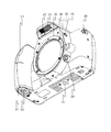
図1はカメラの背面斜視図、図2は正面斜視図である。1はカメラ、2は背蓋であり、該カメラ本体に対して不図示のヒンジで回転して開閉ができるよう固定されている。3は開放つまみで、該開放つまみ3の操作によって不図示のラッチ機構が開放されて開くように構成されている。4はフイルム確認窓で、カメラ内部に装填されたフイルムの在否が確認でき、装填されているときには、パトローネに記載されているフイルムの情報を読み取ることができる。この状態で撮影フイルムの出し入れが行える。閉じるときは本体側に押し付けることでラッチが掛かり、閉じた状態で固定される。
1 is a rear perspective view of the camera, and FIG. 2 is a front perspective view.
5は外部表示液晶であり、カメラの撮影設定状態や、撮影可能枚数などを表示する。ここでは全点灯状態を示している。
6はFUNCマークで、FUNCによって設定される機能を表示している。7はAv+/−ボタンで、マニュアルモード時にはAv+/−ボタンを押しながら後述の電子ダイアル15を操作するとカメラの絞り値を変更することができる。マニュアルモード以外のモードが選択されているときには、同じくAv+/−ボタンを押しながらの電子ダイアル15の操作によって設定された露出値を補正することができる。さらに、SET機能も併せ持ち、時計合わせを行った際の確定ボタンともなる。
8はFUNCボタンでカメラの各種機能の設定を行う。一度FUNCボタン8を押すと、外部表示液晶5の矢印がFUNCマーク6の「DATE」部を指し示し、DATE機能に関しての設定が行える。FUNCボタンを繰り返し押すと、DATE→ISO→赤目→電子音→多重露出→AEBの順に外部表示液晶5の指し示す矢印が移動して、それぞれの状態で電子ダイアル15を操作することによって各機能の設定が行える。
A FUNC button 8 is used to set various camera functions. Once the FUNC button 8 is pressed, the arrow on the external
9は照明ボタンで、一度押すと外部表示液晶5のバックライトが点灯、タイマーによっても自動消灯するが、点灯中に再度押すことで強制的に消灯することができる。10はフイルム途中巻き戻しボタンで、装填されたフイルムを途中で取り出す際に巻き戻しを開始するためのボタンである。11は部分測光・AEロックボタンであり、このボタンを押すと、その時に部分測光したAE値に所定時間固定される。
Reference numeral 9 denotes an illumination button. When the button is pressed once, the backlight of the external
13はドライブボタンで、押すたびに給送モードが”一枚撮影”→”連続撮影”→”セルフタイマ・ワイヤレスリモコン”の順に切り替わる。14はモードダイアルであり、カメラの電源がオフする”OFF”のポジションを境に時計回り回転させると被写体の種類を選択することでカメラが最適な露出を決定するイメージゾーンに、反時計回りに回転させると使用者が思い通りの露出決定を行えるクリエイティブゾーンとなる。ダイアル14上に描かれたアイコンを回転させてモードダイアル指標21に合わせることで、撮影時のカメラの動作モードが決定される。
15は電子ダイアルであり、上記でも説明したように、各種設定時にこれを用いてパラメータを変化させる。16は二段階のストロークを持つレリーズボタンであり、一段階目のクリック(以下SW1と称する)でAF/AEを確定し、二段階目のクリック(以下SW2と称する)にてミラーアップ、シャッタ作動(露光)、ミラーダウン、フイルム給送という一連の撮影動作が行われる。
17はファインダで、ここを覗くことで撮影画像の確認が行える。18は視度調整つまみであり、使用者毎の視力に応じて視度を切り替えることができる。19は内蔵ストロボであり、状況に応じてカメラ、もしくは使用者が必要に応じてアップさせストロボを発光する。20はアクセサリシューであり、外付けストロボのようなアクセサリを取り付けるためのインターフェイスである。21はモードダイアル指標であり、モードダイアル14の選択されているアイコンを指し示す。
22はストロボ発光部であり、ストロボポップアップ時には被写体に向いてストロボ光を射出し光量不足を補う。23は赤目緩和ランプ窓であり、赤目緩和モードでストロボを発光するときには撮影動作直前に所定時間点灯し、被写体となる人物の瞳孔縮小を促し、赤目現象の発生を緩和する。 Reference numeral 22 denotes a strobe light emitting unit. When the strobe pops up, the strobe light is emitted toward the subject to compensate for the insufficient light quantity. Reference numeral 23 denotes a red-eye alleviation lamp window, which is lit for a predetermined time immediately before the photographing operation when the strobe is emitted in the red-eye alleviation mode, urges the reduction of the pupil of the person who is the subject, and alleviates the occurrence of the red-eye phenomenon.
24はワイヤレスリモコン受光窓であり、ワイヤレスリモコンモード時にワイヤレスリモコンからの信号を受光する窓である。また、ワイヤレスリモコン受光窓24は同時にセルフタイマ作動ランプの投光窓も兼ねており、セルフタイマ作動時に点滅して、その動作を被写体となる人物に告知する。25はマウントインターフェースで、不図示のレンズがここに突き当てられ、バヨネット構造によって取り付けられる。
26はマウントロック解除ボタン、27はマウントロックピンで、不図示のレンズを取り外す際には、マウントロック解除ボタン26を押すと、連動してマウントロックピン27と不図示のレンズとの係合が外れ、不図示のレンズは回転可能となってバヨネットから外れることが可能となる。
Reference numeral 26 denotes a mount lock release button, and 27 denotes a mount lock pin. When removing a lens (not shown), when the mount lock release button 26 is pressed, the mount lock pin 27 and the lens (not shown) are engaged with each other. The lens (not shown) can be rotated and can be detached from the bayonet.
28はストロボアップボタンで、撮影モードがクリエイティブゾーンにあるときには、このボタンを押すと自動的に内蔵ストロボ22がポップアップし、撮影時に発光する。29は被写界深度確認ボタンで、このボタンを押すと、撮影待機状態のレンズの絞りが、そのときに設定されている絞りに絞り込まれ、撮影した時の合焦状態を確認することができる。
30はワイヤードリモコンジャックであり、不図示のワイヤードリモコンのプラグをここに差し込むことでワイヤードリモコンによるSW1/SW2の操作が可能となる。31は三脚穴であり、三脚についた三脚ねじをここにねじ込むことで、カメラと三脚が一体に固定される。32は電池蓋、33は電池蓋開放レバーであり、電池蓋開放レバー32を操作すると電池蓋32が開放されて、電池の挿抜が可能となる。
Reference numeral 30 denotes a wired remote control jack. By inserting a plug of a wired remote control (not shown) here, the SW1 / SW2 can be operated by the wired remote control.
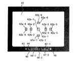
次に、ファインダ17について詳細に説明する。図3はカメラ1のファインダ17内を表したものである。
Next, the
41はファインダ視野枠であり、カメラ1が撮影できる範囲を指し示す。42a−1〜42a−7は測距枠であり、AF動作を行うことができるエリアを指し示している。42b−1〜42b−7はスーパーインポーズ(以下SI)表示点であり、測距枠42a−1〜42a−7の中からカメラが所定のアルゴリズムに基づいて選択した測距点、もしくはユーザーが任意に選択したから選択した測距枠を指し示すための指標である。通常は黒い点として見えているが、選択された測距点を表示する際にはLEDによって照明されて赤く光る。
43〜48は複数の表示パターンが設けられたファインダ内表示LCD(表示素子)であり、便宜上全点灯状態で示している。43はAEロック/FEロックマークであり、AEロックもしくはFEロックをしているときに点灯する。44はストロボマークであり、ストロボの状態を表示する。45はハイスピードシンクロマークで、所定のシャッタ速度よりも早いシャッタ速度でのストロボ撮影を行うときに表示される。
46−1はシャッタ速度表示マーク、46−2は絞り表示マーク、47−1は露出レベル表示指標、47−2は露出レベル表示目盛りであり、これらによって露出レベルに関する情報を表示したり、赤目ランプ作動中には露出レベル表示指標47−1によって赤目ランプが作動中である旨の表示を行う。48は合焦マークであり、合焦すると点灯、合焦ができないときには点滅する。
Reference numeral 46-1 denotes a shutter speed display mark, 46-2 denotes an aperture display mark, 47-1 denotes an exposure level display index, and 47-2 denotes an exposure level display scale. During operation, an indication that the red-eye lamp is in operation is displayed by the exposure level display indicator 47-1.
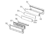
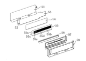
続いて、ファインダLCDユニットの構成を図4〜図6に基づいて説明する。なお、本実施例では組立順にファインダLCDユニットの構成を説明する。 Next, the configuration of the finder LCD unit will be described with reference to FIGS. In this embodiment, the configuration of the finder LCD unit will be described in the order of assembly.
51はファインダLCDホルダである。まず、発光素子であるファインダLED52を実装したファインダFPC53を落とし込み、さらに反射シート54、ライトガイド55を落とし込む。ファインダLCDホルダ51とライトガイド55で作られる空隙部に異方性導電ゴム56を挿入する。これらの上にファインダLCD57をのせて押さえ板58で押さえ込む。この時異方性導電ゴム56は圧縮されて導電性を生じ、ファインダFPC53とファインダLCD57とを電気的に接続する。
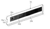
また、ライトガイド55は、ファインダLED52を覆うように形成された入射部55aが設けられ、ファインダLED52からの光を漏らさないようにしている。さらに、ライトガイドの第1の領域には、入射部55aから入光してくる光を反射する反射部を構成マット面55bが設けられ、光を照射することが必要なエリアにのみドット55dの繰り返しによるマット処理が施されている。入射部55aから入光した光は拡散してしまうので、入射部55aから離れるに従って光密度は小さくなり、反射光の明るさも低くなっていく。そこで、入射部55aから徐々に離れていくに従ってドット部55dの密度を増してファインダでの見た目の明るさが均一になるように構成している。
Further, the
そして、ライトガイド55には、合焦マーク48の裏側に位置するマット面55bのエリアにおいて、第1の領域に形成されたドット部55dよりも形成密度の高いドット部55eによるマット処理が施された第2の領域、すなわち、合焦マーク48等の特定の表示パターンに対応し、かつ近接又は周囲に形成された第1の領域の反射部のドット部55dよりも形成密度の高い第2の領域が設けられている。
The
このように構成されたファインダLCDユニットは、不図示のカメラ制御回路によってファインダLCD57を駆動するべくファインダFPC53に通電するとファインダLCD57は所定のマークが点灯、もしくは点滅する。同時にカメラ制御回路によってファインダLED52を駆動するべくファインダFPC53に通電するとファインダLED52が点灯し、その光はライトガイド55の入射部55aの端面55cを照明する。端面55cから入光した光は裏面に形成されたマット面55bによって反射されてファインダLCD57側に射出される。また、マット面55bを透過してしまった光は反射シート54によって反射されて再度ライトガイド55の中に戻される。このようにしてファインダLCD57のバックライトとして機能する。
In the finder LCD unit configured as described above, when a
本実施例によれば、ライトガイド55に光をファインダLCD57側(表示素子側)に反射する反射部であるマット面55bには、特定の表示パターン以外の表示パターンに対応する第1の領域と、該特定の表示パターンに対応する第2の領域とが設けられ、第2の領域における反射部(ドット部55e)の形成密度が第1の領域に施されたドット部55dのドット密度(形成密度)よりも高く構成されている。
According to the present embodiment, the
よって、第1の領域に対応して設けられる他の表示パターンよりも第2の領域に対応する特定の表示パターンを明るく表示することができるとともに、第2の領域における反射部の形成密度が高いことから該特定の表示パターンを通して該反射部が見えることによる不自然さを低減させることが可能となる。 Therefore, a specific display pattern corresponding to the second region can be displayed brighter than other display patterns provided corresponding to the first region, and the formation density of the reflection portions in the second region is high. For this reason, it is possible to reduce unnaturalness due to the reflection part being visible through the specific display pattern.
したがって、拡大して観察する広い面積を用いた表示、例えば、合焦マーク48であってもドットの粒子は気にならず、かつ、ユーザーが合焦した瞬間にレリーズ動作を行うために、瞬間的に他の表示に対して明るく表示して注意(認知)を促すことができる。
Therefore, a display using a wide area to be magnified and observed, for example, even if it is the
以上、本実施例では、カメラのファインダ表示に適応しているが、同様の構成はカメラの外部表示に対しても適応でき、さらには、その他のバックライト付きLCD表示を用いた電子光学機器に対しても適応できる。 As described above, the present embodiment is adapted to the camera finder display, but the same configuration can be adapted to the external display of the camera, and moreover to other electro-optical devices using a backlit LCD display. It can also be applied to.
さらに、照明装置としてLEDを用いているが、これは電球や蛍光管などを用いても構成可能であり、照明機構を限定するものではない。 Furthermore, although LED is used as an illuminating device, this can also be configured using a light bulb or a fluorescent tube, and does not limit the illumination mechanism.
また、本実施例は、デジタルカメラにも適用することができる。例えば、フィルムでの撮影の代わりに、カメラ1内にCCD、C-MOSセンサ等の撮像素子が設けられて、撮影光学系によって形成された光学像を電気信号に光電変換し、該撮像素子から読み出された電気信号をカメラ1内に設けられた画像処理回路によって映像信号に変換して表示ユニット等に表示させたり、映像信号が記憶されるメモリの容量等から撮影可能枚数を判断し、表示ユニットに撮影可能枚数を表示させるなどの構成を採用することにより適用可能である。
The present embodiment can also be applied to a digital camera. For example, instead of shooting with a film, an image pickup device such as a CCD or C-MOS sensor is provided in the
1 カメラ
52 ファインダLED(発光素子)
55 ライトガイド
55a 入射部
55b 反射部
57 ファインダLCD(表示素子)
1
55
Claims (4)
発光素子と、
前記表示素子の背面側に配置され、前記発光素子からの光を前記表示素子側に反射する複数の反射部が形成されたライトガイドとを有し、
前記ライトガイドは、前記発光素子のうち特定の表示パターン以外の表示パターンに対応する第1の領域と、前記特定の表示パターンに対応する第2の領域とを有し、前記第2の領域における前記反射部の形成密度が前記第1の領域のうち該第2の領域に近接する部分の前記反射部の形成密度より高いことを特徴とする表示装置。 A display element having a display pattern that transmits light;
A light emitting element;
A light guide disposed on the back side of the display element and formed with a plurality of reflecting portions for reflecting light from the light emitting element to the display element side;
The light guide includes a first region corresponding to a display pattern other than a specific display pattern among the light emitting elements, and a second region corresponding to the specific display pattern. In the second region, The display device, wherein a formation density of the reflection portion is higher than a formation density of the reflection portion in a portion of the first region adjacent to the second region.
前記表示装置は、該カメラのファインダ内で表示を行うことを特徴とする請求項3に記載のカメラ。 The optical device is a camera;
The camera according to claim 3, wherein the display device performs display in a finder of the camera.
Priority Applications (1)
| Application Number | Priority Date | Filing Date | Title |
|---|---|---|---|
| JP2004109234A JP2005292591A (en) | 2004-04-01 | 2004-04-01 | Display device and camera |
Applications Claiming Priority (1)
| Application Number | Priority Date | Filing Date | Title |
|---|---|---|---|
| JP2004109234A JP2005292591A (en) | 2004-04-01 | 2004-04-01 | Display device and camera |
Publications (1)
| Publication Number | Publication Date |
|---|---|
| JP2005292591A true JP2005292591A (en) | 2005-10-20 |
Family
ID=35325557
Family Applications (1)
| Application Number | Title | Priority Date | Filing Date |
|---|---|---|---|
| JP2004109234A Pending JP2005292591A (en) | 2004-04-01 | 2004-04-01 | Display device and camera |
Country Status (1)
| Country | Link |
|---|---|
| JP (1) | JP2005292591A (en) |
Cited By (1)
| Publication number | Priority date | Publication date | Assignee | Title |
|---|---|---|---|---|
| CN118067741A (en) * | 2024-04-18 | 2024-05-24 | 成都考拉悠然科技有限公司 | Mini-LED adhesive surface defect detection method based on photometric stereo method |
-
2004
- 2004-04-01 JP JP2004109234A patent/JP2005292591A/en active Pending
Cited By (1)
| Publication number | Priority date | Publication date | Assignee | Title |
|---|---|---|---|---|
| CN118067741A (en) * | 2024-04-18 | 2024-05-24 | 成都考拉悠然科技有限公司 | Mini-LED adhesive surface defect detection method based on photometric stereo method |
Similar Documents
| Publication | Publication Date | Title |
|---|---|---|
| CN100510937C (en) | Finder device and camera | |
| CN102469266A (en) | Imaging apparatus | |
| JPH08242398A (en) | Imaging device | |
| JP5874009B2 (en) | Imaging device | |
| JP2005292591A (en) | Display device and camera | |
| JP2005241750A (en) | Display device and camera | |
| JP3890098B2 (en) | Optical device | |
| JP2007020125A (en) | Imaging device | |
| JP6657805B2 (en) | Optical equipment | |
| JP2006313978A (en) | Imaging apparatus, control method, and computer program | |
| JPH11231408A (en) | Camera for both silver halide photography and electronic imaging | |
| JP2006339902A (en) | Finder device and camera | |
| JP4109943B2 (en) | Auto focus camera | |
| JP2005257869A (en) | Imaging device | |
| JP2003029317A (en) | Lens barrel and camera | |
| JP2006047702A (en) | camera | |
| JP2006047391A (en) | Display device and imaging device | |
| JPH1090779A (en) | Camera | |
| JP2008309840A (en) | Camera system and camera | |
| JP2007086181A (en) | Imaging apparatus, imaging method, and program | |
| JP2006048953A (en) | Display device and imaging device | |
| JPH10239749A (en) | Still camera | |
| US6571065B1 (en) | Specification-variable camera | |
| JP2002131805A (en) | Electronic viewfinder device of camera | |
| JP2000292682A (en) | Automatic focus adjustment device |