JP2005292726A - Sound environment detecting device and program - Google Patents
Sound environment detecting device and program Download PDFInfo
- Publication number
- JP2005292726A JP2005292726A JP2004111394A JP2004111394A JP2005292726A JP 2005292726 A JP2005292726 A JP 2005292726A JP 2004111394 A JP2004111394 A JP 2004111394A JP 2004111394 A JP2004111394 A JP 2004111394A JP 2005292726 A JP2005292726 A JP 2005292726A
- Authority
- JP
- Japan
- Prior art keywords
- output level
- sound
- envelope
- data
- reference data
- Prior art date
- Legal status (The legal status is an assumption and is not a legal conclusion. Google has not performed a legal analysis and makes no representation as to the accuracy of the status listed.)
- Withdrawn
Links
- 238000012545 processing Methods 0.000 claims abstract description 36
- 230000005236 sound signal Effects 0.000 claims abstract description 25
- 238000005070 sampling Methods 0.000 claims abstract description 13
- 238000001514 detection method Methods 0.000 claims description 41
- 238000012544 monitoring process Methods 0.000 claims description 37
- 238000011156 evaluation Methods 0.000 claims description 4
- 230000002123 temporal effect Effects 0.000 abstract description 3
- 230000005856 abnormality Effects 0.000 description 14
- 238000010295 mobile communication Methods 0.000 description 9
- 238000004891 communication Methods 0.000 description 8
- 230000006870 function Effects 0.000 description 8
- 238000000034 method Methods 0.000 description 7
- 238000012986 modification Methods 0.000 description 7
- 230000004048 modification Effects 0.000 description 7
- 230000002265 prevention Effects 0.000 description 5
- 238000010586 diagram Methods 0.000 description 4
- 238000005516 engineering process Methods 0.000 description 3
- 238000006243 chemical reaction Methods 0.000 description 1
- 238000007796 conventional method Methods 0.000 description 1
- 230000000694 effects Effects 0.000 description 1
- 239000000284 extract Substances 0.000 description 1
- 238000007726 management method Methods 0.000 description 1
- 238000012806 monitoring device Methods 0.000 description 1
Images

Landscapes
- Measurement Of Mechanical Vibrations Or Ultrasonic Waves (AREA)
- Emergency Alarm Devices (AREA)
Abstract
Description
施設内の状況をその施設内の音に基づいて把握する技術に関する。 The present invention relates to a technique for grasping a situation in a facility based on sound in the facility.
会議室や家屋などの施設内の音を記録し、その施設の防犯監視に利用したり、その音の時間変化に基づいてその施設の利用状況を把握したりすることが行われている。このような技術の一例としては、特許文献1に開示された技術が挙げられる。特許文献1には、カメラが撮像した監視映像やマイクが集音した音声を記録する防犯監視装置に、上記カメラの周囲の状態を検出する検出センサを設け、その検出センサが検出する周囲の状態が所定の状態と異なった場合に異常が発生したと判定し、上記監視映像や音声の記録を開始させるようにすることが開示されている。また、長時間に渡って記録した音や映像の中から所望の部分を効率良く検索することを可能にする技術も種々提案されており、その一例としては、特許文献2に開示された技術が挙げられる。特許文献2には、会議や講演などの音声や画像を記録する際に、その音声や画像の変わり目に、会議メモなどユーザが適宜入力したデータを関連付けて記録し、記録した音声や画像の中から所望の部分を検索する際に、そのデータをキーとして係る検索を容易にすることが開示されている。
Sounds in facilities such as conference rooms and houses are recorded and used for crime prevention monitoring of the facilities, and the use status of the facilities is grasped based on temporal changes of the sounds. An example of such a technique is the technique disclosed in
ところで、特許文献1や2に開示された技術のように、施設内の音を長時間に渡ってそのまま記録する場合には、大容量の記憶装置が必要になり、その監視に要するコストが高くなってしまう。何故ならば、記憶装置の価格は、その記憶容量が大きくなるほど高くなるからである。また、施設内の音をそのまま記録する態様では、その施設内で為されている会話の内容もそのまま記録されてしまうことになるが、このような記録が為されていることをその会話者が了承している場合以外には、その会話者のプライバシーを侵害することに為りかねず、好ましくない。
By the way, when the sound in the facility is recorded as it is for a long time as in the techniques disclosed in
本発明は上記課題に鑑みて為されたものであり、プライバシーを侵害することなく施設内の音の時間変化を記録するとともに、その記録に要する記憶容量を削減することを可能にする技術を提供することを目的としている。 The present invention has been made in view of the above-described problems, and provides a technique that enables recording the time change of sound in a facility without infringing on privacy and reducing the storage capacity required for the recording. The purpose is to do.
上記課題を解決するために、本発明は、記憶手段と、入力された音信号の信号波形の包絡線を生成する信号処理手段と、前記信号処理手段により生成された包絡線の出力レベルを予め定められた時間間隔でサンプリングし、そのサンプリング結果に応じた出力レベルデータを生成する生成手段と、前記出力レベルデータを前記記憶手段へ書き込む書き込み手段とを有する音環境検出装置を提供する。 In order to solve the above-described problems, the present invention provides a storage unit, a signal processing unit that generates an envelope of a signal waveform of an input sound signal, and an output level of the envelope generated by the signal processing unit in advance. There is provided a sound environment detection apparatus including a generation unit that samples at a predetermined time interval and generates output level data corresponding to the sampling result, and a writing unit that writes the output level data into the storage unit.
また、上記課題を解決するために、本発明は、コンピュータ装置に、入力された音信号の信号波形の包絡線を生成する信号処理機能と、前記信号処理機能により生成された包絡線の出力レベルを予め定められた時間間隔でサンプリングし、そのサンプリング結果に応じた出力レベルデータを生成する生成機能と、前記出力レベルデータを記憶する記憶機能とを実現させるためのプログラムを提供する。 In order to solve the above problems, the present invention provides a computer apparatus with a signal processing function for generating an envelope of a signal waveform of an input sound signal, and an output level of the envelope generated by the signal processing function. Is provided at a predetermined time interval, and a program for realizing a generation function for generating output level data according to the sampling result and a storage function for storing the output level data is provided.
このような音環境検出装置およびプログラムによれば、入力された音信号の包絡線の出力レベルが所定の時間間隔でサンプリングされて記憶される。例えば、上記音環境検出装置や上記プログラムにしたがって作動しているコンピュータ装置に、監視対象の施設内の音に対応する音信号が入力されるようにすれば、その施設内の音の信号波形の包絡線の出力レベルが所定の時間間隔でサンプリングされて上記音環境検出装置や上記コンピュータ装置に記憶される。 According to such a sound environment detection apparatus and program, the output level of the envelope of the input sound signal is sampled and stored at predetermined time intervals. For example, if the sound signal corresponding to the sound in the facility to be monitored is input to the sound environment detection device or the computer device operating according to the program, the signal waveform of the sound in the facility The output level of the envelope is sampled at a predetermined time interval and stored in the sound environment detection device or the computer device.
本発明によれば、施設内の音に対応する音信号をそのまま記録するのではなく、その包絡線の示す出力レベルを所定の時間間隔でサンプリングして記録するので、その記録に要する記憶容量を削減することが可能になる。加えて、本発明によれば、監視対象の施設内でどのような会話が為されていても、その会話内容がそのまま記録されることはないので、その会話者のプライバシーが侵害されることもない。 According to the present invention, the sound signal corresponding to the sound in the facility is not recorded as it is, but the output level indicated by the envelope is sampled and recorded at a predetermined time interval. It becomes possible to reduce. In addition, according to the present invention, no matter what kind of conversation is made in the monitored facility, the conversation content is not recorded as it is, and the privacy of the talker may be infringed. Absent.
以下、本発明を実施するための最良の形態について図面を参照しつつ説明する。
[A.構成]
(A−1:システム構成)
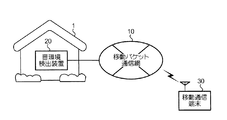
図1は、本発明の1実施形態に係る音環境検出装置20を有する防犯監視システムの構成例を示す図である。図1に示されているように、この防犯監視システムは、家屋など監視対象の施設1内に設置され、移動パケット通信網10に接続された音環境検出装置20と、この移動パケット通信網10に収容される携帯電話機である移動通信端末30とを有している。
The best mode for carrying out the present invention will be described below with reference to the drawings.
[A. Constitution]
(A-1: System configuration)
FIG. 1 is a diagram illustrating a configuration example of a crime prevention monitoring system having a sound
図1の音環境検出装置20は、マイクロホンなどの集音手段を備えており、その集音手段により施設1内の音を集音しその音の時間変化を記録するとともに、集音した音に基づいて施設1内で異常が発生したか否かを評価し、その評価結果に応じた警報情報を発信することができる。具体的には、図1に示す防犯監視システムでは、音環境検出装置20は、施設1内で異常が発生したと評価すると、上記警報情報として所定の電子メールを移動パケット通信網10を介して移動通信端末30へ送信する。一方、移動通信端末30は、音環境検出装置20から送信された電子メールをユーザに閲覧させ、施設1内で何らかの異常が発生したことをそのユーザに把握させることができる。なお、本実施形態では、上記警報情報として電子メールを用いる場合について説明するが、所定の警報音を移動通信端末30に放音させるための音データや、所定の振動数および振動パターンで移動通信端末30を振動させるための制御データなどを警報情報として用いても良いことは勿論である。
The sound
図1の音環境検出装置20が、前述した特許文献1に開示された防犯監視装置や特許文献2に開示された情報記憶装置などの従来技術と異なっている点は、上記集音手段により集音された音の時間変化を記録する際に、その音の信号波形をそのまま記録するのではなく、その信号波形の包絡線(以下、エンベロープとも呼ぶ)を表す出力レベルデータを生成し記憶する点である。具体的には、音環境検出装置20は、上記包絡線の出力レベルを予め定められた時間間隔(例えば、30分間隔)でサンプリングして、上記出力レベルデータを生成し記憶する。このような出力レベルデータを記憶するようにしたため、上記信号波形をそのまま記録する従来の技術に比較して、その記録に要する記憶容量を削減することが可能になる。つまり、本実施形態に監視システムによれば、大容量の記憶装置を要することなく、監視対象の施設1内の音の時間変化を記録することが可能になる。加えて、施設1内で交わされている会話がそのまま記録されることはないので、その会話者のプライバシーが侵害される虞もない。以下、本実施形態に係る監視システムの特徴を顕著に示している音環境検出装置20を中心に説明する。
The sound
(A−2:音環境検出装置20の構成)
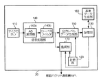
図2は、音環境検出装置20のハードウェア構成の一例を示す図である。図2に示されているように、音環境検出装置20は、上記集音手段として機能するマイクロホン110と、計時部120と、記憶部130と、信号処理部140と、出力レベルデータ生成部150と、基準データ生成部160と、監視部170とを含んでいる。
(A-2: Configuration of the sound environment detection device 20)
FIG. 2 is a diagram illustrating an example of a hardware configuration of the sound
計時部120は、例えばリアルタイムクロックであり、現在時刻を表す時刻データを出力レベルデータ生成部150や監視部170へ随時供給するためのものである。記憶部130は、例えばハードディスクであり、前述した出力レベルデータや、上記マイクロホンにより集音された音の出力レベルを評価する際の基準となる基準データなどを格納するためのものである。
The
信号処理部140は、マイクロホン110から引渡された音信号に所定の信号処理を施しその音信号の包絡線を表すエンベロープデータに変換するものである。図2に示すように、この信号処理部140は、AD変換器140aと、ローパスフィルタ140bとを含んでいる。AD変換器140aは、上記マイクロホン110から入力された音信号をデジタルデータへ変換しローパスフィルタ140bへ引渡すためのものである。一方、ローパスフィルタ140bは、AD変換器140aより引渡されたデジタルデータから高調波成分を除去して上記エンベロープデータに変換し出力レベルデータ生成部150と監視部170とへ引渡すものである。
The
出力レベルデータ生成部150は、信号処理部140から引渡されたエンベロープデータの示す出力レベルを所定の時間間隔でサンプリングして出力レベルデータを生成し、記憶部130へ書き込むものである。本実施形態では、この出力レベルデータ生成部150は、上記サンプリングを行うべき時刻(例えば、午前0時から30分間隔の時刻)を表すデータが格納された時刻テーブルを記憶しており、計時部120から供給された時刻データに対応する時刻が時刻テーブルに格納されている時刻と一致した場合に、その時刻データに対応する時刻と、信号処理部140から引渡されたエンベロープデータの表す出力レベルとを対応付けて上記出力レベルデータを生成し記憶部130へ書き込むものである。
The output level
基準データ生成部160は、記憶部130に記憶されている出力レベルデータを読み出し、この出力レベルデータに所定の統計処理を施して上記基準データを生成し記憶部130へ書き込むものである。本実施形態では、基準データ生成部160は、記憶部130に格納されている出力レベルデータの示す出力レベルの時間帯毎の平均値を算出し、その平均値を各時間帯毎の基準データとして記憶部130へ書き込む。なお、本実施形態では、上記平均値を基準データとして用いる場合について説明するが、各時間帯における出力レベルの最頻出値を上記基準データとして用いるとしても良く、また、中央値を上記基準データとして用いるとしても勿論良い。
The reference
監視部170は、例えば専用線や公衆回線などの通信回線を介して移動パケット通信網10に接続されており、施設1内の音の出力レベルに基づいて、異常の発生の有無を評価しその評価結果に応じた警報情報を移動パケット通信網10を介して移動通信端末30へ送信するものである。より詳細に説明すると、監視部170は、計時部120から供給された時刻データの示す時刻に対応する基準データを記憶部130から読み出し、この基準データの示す出力レベルと信号処理部140から引渡されたエンベロープデータの示す出力レベルとの差が所定の閾値を超えた場合に、施設1内で異常が発生したと判定し、上記警報情報を移動通信端末30へ送信する。
The
以上に説明したように、本実施形態では、本発明に係る音環境検出装置に特有な機能をハードウェアモジュールで実現する場合について説明したが、これら各機能をソフトウェアモジュールで実現するとしても良いことは勿論である。また、CPU(Central Processing Unit)などの制御部に上記ソフトウェアモジュールを実現させるプログラムを例えばCD−ROM(Compact Disk-Read Only Memory)などのコンピュータ装置読み取り可能な記録媒体に記憶させておき、係る記録媒体を用いて上記プログラムを一般的なコンピュータ装置にインストールし、本実施形態に係る音環境検出装置20と同一の機能を付与することも可能である。
As described above, in the present embodiment, a case has been described in which functions specific to the sound environment detection device according to the present invention are realized by hardware modules. However, these functions may be realized by software modules. Of course. Further, a program for realizing a software module in a control unit such as a CPU (Central Processing Unit) is stored in a computer-readable recording medium such as a CD-ROM (Compact Disk-Read Only Memory) and the recording is performed. It is also possible to install the above program in a general computer device using a medium and give the same function as the sound
[B.動作]
次いで、本実施形態に係る音環境検出装置20が行う動作について図面を参照しつつ説明する。
(B−1:記録動作)
まず、前述した出力レベルデータを記録する記録動作について説明する。
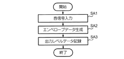
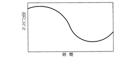
図3は、音環境検出装置20が行う記録動作の流れを示すフローチャートである。音環境検出装置20の周囲の音がマイクロホン110により集音されると、図3に示されているように、その音に対応する音信号(例えば、図4に示す信号波形を有する音信号)が信号処理部140へ入力される(ステップSA1)。
[B. Operation]
Next, operations performed by the sound
(B-1: Recording operation)
First, a recording operation for recording the above-described output level data will be described.
FIG. 3 is a flowchart showing the flow of the recording operation performed by the sound
信号処理部140は、入力された音信号に所定の信号処理(本実施形態では、デジタルデータへの変換および高調波成分の除去)を施して、前述したエンベロープデータを生成し(ステップSA2)、そのエンベロープデータを出力レベルデータ生成部150へ引渡す。例えば、図4に示す信号波形を有する音信号が信号処理部140へ入力されると、上記信号処理を施した結果、図5に示す信号波形を表すエンベロープデータが出力レベルデータ生成部150へ引渡される。
The
一方、出力レベルデータ生成部150は、計時部120から引渡された時刻データの示す時刻が前述した時刻テーブルに格納されているデータの表す時刻に一致した場合に、上記エンベロープデータの示す出力レベルをサンプリングしその時刻を表すデータと対応付けて上述した出力レベルデータを生成し、記憶部130へ書き込む(ステップSA3)。例えば、上記時刻テーブルに、午前0時から30分毎の時刻を表すデータが格納されている場合には、施設1内の音の時間変化を表す出力レベルデータとして、1日あたり48組の出力レベルと時刻との組が上記出力レベルデータとして記憶部130に書き込まれることになる。
On the other hand, the output level
このように、本実施形態に係る音環境検出装置20によれば、施設1内の音の音信号をそのまま記録する場合に比較して、その記録に要する記憶容量を削減させることが可能になる。また、上記出力レベルデータは、各時刻における施設1内の音の出力レベルのみを表しているため、その施設1内でどのような会話が為されていても、その会話の内容が第3者に把握される虞はなく、その会話の会話者のプライバシーが侵害される虞もない。さらに、マイクロホン110によって集音された音に対応する音信号の出力レベルそのものを所定の時間間隔でサンプリングしてしまうと、サンプリング結果がそのサンプリングタイミングに大きく依存してしまうが、上記音信号の包絡線の出力レベルをサンプリングするようにしたため、その依存性を抑えることが可能になる。
Thus, according to the sound
(B−2:基準データ生成動作)
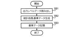
次いで、記憶部130に記憶されている出力レベルデータに基づいて、上述した基準データを生成する基準データ生成動作について図6を参照しつつ説明する。図6は、基準データを生成する旨の指示が図示せぬ操作部を介して入力された場合に、基準データ生成部160が行う基準データ生成動作の流れを示すフローチャートである。図6に示されているように、基準データ生成部160は、まず、出力レベルデータを記憶部130から読み出し(ステップSB1)、所定の統計処理を施して基準データを生成する(ステップSB2)。前述したように、本実施形態では、基準データ生成部160は、上記出力レベルデータの示す出力レベルの時間帯毎の平均値を上記基準データとして算出する。例えば、上述した48組の出力レベルと時刻との組からなる出力レベルデータが記憶部130に記憶されている場合には、午前0時から午前2時までの時間帯については、基準データ生成部160は、午前0時、午前0時30分、午前1時および午前1時30分の各時刻に該当する出力レベルの平均値を上記基準データとして算出する。
(B-2: Reference data generation operation)
Next, the reference data generation operation for generating the above-described reference data based on the output level data stored in the
そして、基準データ生成部160は、上記ステップSB2にて生成した基準データを各時間帯毎に記憶部130へ書き込み(ステップSB3)、当該基準データ生成処理を完了する。なお、本実施形態では、1つの出力レベルデータに基づいて各時間帯毎の基準データを生成する場合について説明したが、複数の出力レベルデータに基づいて各時間帯毎の基準データを生成するとしても勿論良い。具体的には、上記複数の出力レベルデータの各々が示す出力レベルを各時間帯毎に集計して各時間帯毎の出力レベルの平均値を求め、その平均値を上記基準データとして用いるようにすれば良い。
Then, the reference
(B−3:監視動作)
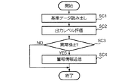
次いで、記憶部130に記憶されている基準データに基づいて、施設1内の音の出力レベルを評価し異常の発生の有無を監視する監視動作について図7を参照しつつ説明する。図7は、上記監視を開始する旨の指示が図示せぬ操作部を介して入力された場合に、監視部170が行う監視動作の流れを示すフローチャートである。図7に示されているように、監視部170は、まず、計時部120から供給された時刻データに対応する基準データを記憶部130から読み出す(ステップSC1)。例えば、午前0時から午前8時までの時間帯、午前8時から午後6時までの時間帯および午後6時から翌日の午前0時までの時間帯の3つの時間帯についての基準データが記憶部130に記憶されている状況下で、上記時刻データが“午前10時”を示している場合には、監視部170は、午前8時から午後6時の時間帯に対応する基準データを記憶部130から読み出す。次いで、監視部170は、信号処理部140から引渡されたエンベロープデータの示す出力レベルを、ステップSC1にて読み出した基準データに基づいて評価し(ステップSC2)、その評価結果に基づいて、施設1内で異常が発生したか否かを判定する(ステップSC3)。具体的には、監視部170は、上記ステップSC2にてエンベロープデータの示す出力レベルと、ステップSC1にて読み出した基準データの示す出力レベルとの差を求め、その差が所定の閾値を超えている否かを上記ステップSC3で判定し、その閾値を超えている場合に異常が発生したと判定する。
(B-3: Monitoring operation)
Next, a monitoring operation for evaluating the sound output level in the
そして、監視部170は、ステップSC3の判定結果が“Yes”である場合には、所定の警報情報を移動パケット通信網10を介して移動通信端末30へ送信し(ステップSC4)、逆に、ステップSC3の判定結果が“No”である場合には、上記警報情報の送信を行わない。以下、監視部170は、監視動作の終了を指示されるまで、上述したステップSC1以降の処理を繰り返し実行する。
When the determination result in step SC3 is “Yes”, the
[C.変形]
以上、本発明の1実施形態について説明したが、係る実施形態に以下に述べるような変形を加えても良いことは勿論である。
(C−1:変形例1)
上述した実施形態では、本発明に係る音環境検出装置を用いて監視システムを構成する場合について説明したが、本発明の適用対象は、防犯監視システムに限定されるものではない。例えば、本発明に係る音環境検出装置を会議室などの共用施設に設置し、その施設の利用状況の把握に用いるとしても良く、また、上記音環境検出装置を作業卓などに設置し、その作業卓で作業を行う人員の勤怠管理に用いるとしても勿論良い。
[C. Deformation]
Although one embodiment of the present invention has been described above, it is needless to say that the embodiment may be modified as described below.
(C-1: Modification 1)
In the above-described embodiment, the case where the monitoring system is configured using the sound environment detection device according to the present invention has been described. However, the application target of the present invention is not limited to the crime prevention monitoring system. For example, the sound environment detection device according to the present invention may be installed in a common facility such as a conference room and used for grasping the use status of the facility, and the sound environment detection device is installed in a work table or the like. Of course, it may be used for attendance management of personnel who work on the work desk.
(C−2:変形例2)
上述した実施形態では、施設1内の音の信号波形の包絡線の出力レベルを所定の時間間隔でサンプリングして、施設1内の音の時間変化を表す出力レベルデータを生成する場合について説明した。しかしながら、上記包絡線の出力レベルを所定の時間間隔でサンプリングした後に、そのサンプリング結果に所定の係数を乗算したり、所定の値を加算又は減算して上記出力レベルデータを生成するとしても良い。さらに、施設1内の音の時間変化の特徴がより際だつような処理を施してから上記出力レベルデータを生成するとしても勿論良い。このような処理の一例としては、サンプリングされた出力レベルの自己相関を求めること(すなわち、その出力レベルを2乗した値を求めること)が挙げられる。
(C-2: Modification 2)
In the embodiment described above, a case has been described in which the output level of the sound signal waveform in the
(C−3:変形例3)
上述した実施形態では、記憶部130に記憶されている出力レベルデータに基づいて、各時間帯毎の基準データを生成したり、施設1内の異常の有無をその基準データに基づいて各時間帯毎に異なる基準で監視する場合について説明した。しかしながら、出力レベルデータ生成部150や基準データ生成部160、監視部170に現在日付や曜日を表す日付データを供給するカレンダ部を音環境検出装置20に設け、各日付毎に出力レベルデータを記録させたり、その出力レベルデータに基づいて各曜日毎、各時間帯毎の基準データを生成させたり、その基準データを用いて施設1内の異常の有無を曜日毎、各時間帯毎に監視させるとしても勿論良い。このようにすると、施設1の利用状況を各曜日毎、各時間帯毎に把握したり、施設1内の異常の有無を各曜日毎、各時間帯毎に異なる基準で監視することが可能になるといった効果を奏する。
(C-3: Modification 3)
In the above-described embodiment, reference data for each time zone is generated based on the output level data stored in the
(C−4:変形例4)
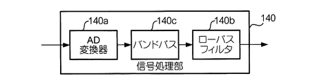
上述した実施形態では、マイクロホン110により集音された音の出力レベルの時間変化を表す波形のエンベロープを抽出する場合について説明したが、上記音の特定の周波数成分(例えば、人間の音声に対応する周波数帯域に属する周波数成分)についてのみ上記エンベロープを抽出するとしても良く、また、各周波数帯域毎に上記エンベロープを抽出するとしても勿論良い。このようなことは、図8に示されているように、信号処理部140に、AD変換器140aから出力されるデジタルデータのうち、上記周波数帯域に対応する部分を抽出してローパスフィルタ140bへ引渡すバンドパス140cを設けておくことによって実現される。また、係るバンドパスを周波数帯域毎に複数設け、各周波数帯域の各々について上記エンベロープを抽出するとしても勿論良い。
(C-4: Modification 4)
In the embodiment described above, the case of extracting the envelope of the waveform representing the time change of the output level of the sound collected by the
(C−5:変形例5)
上述した実施形態では、監視対象の施設1内で異常が発生したか否かを判定する際の基準となる基準データを、記憶部130に記憶させた出力レベルデータに基づいて生成する場合について説明した。この基準データは、音環境検出装置20を利用しているユーザが、単身者であるか、既婚者であるか、また、既婚者である場合には、配偶者が専業主婦であるか否かによって、異なるものになることが想定される。何故ならば、上記ユーザが単身者であるか、既婚者であるかによって、各時間帯に施設1内に居る人数が異なり、施設1内で集音される音の出力レベルも異なるものになると想定されるからである。つまり、上記基準データは、音環境検出装置20を利用するユーザの生活態様(単身者であるか、既婚者であるか、また、そのユーザの勤務時間など)に応じて異なるものになるはずである。この点に着目して、例えば、独身者用、既婚者用および既婚者(共働き)用など、予め何種類かの基準データを記憶部130に格納しておき、音環境検出装置20を利用するユーザの生活態様に即した基準データを選択させ、その基準データに基づいて上記監視動作を行わせるとしても勿論良い。このようにすると、出力レベルデータを記憶部130に蓄積し音環境検出装置20を利用しているユーザの生活態様をその音環境検出装置20に学習させるための学習期間を設けることなく、施設1内で異常が発生したか否かを監視することが可能になるといった効果を奏する。また、予め記憶部130に記憶させておいた基準データを、上記出力レベルデータで随時更新するとしても勿論良い。このようにすると、上記学習期間を設けることなく上記監視を行うことが可能になるとともに、その基準データをユーザの生活態様に即してカスタマイズすることが可能になる。
(C-5: Modification 5)
In the above-described embodiment, a case is described in which the reference data serving as a reference for determining whether or not an abnormality has occurred in the monitored
(C−6:変形例6)
上述した実施形態では、施設1内の音を集音するためのマイクロホンを音環境検出装置20に設けておく場合について説明したが、マイクロホンを接続するための入力端子を音環境検出装置に設け、この入力端子に入力された音信号を信号処理部140へ引渡すようにするとしても勿論良い。要は、監視対象の施設内の音に対応する音信号が信号処理部140へ入力される態様であれば、何れであっても良い。
(C-6: Modification 6)
In the above-described embodiment, the case where the microphone for collecting the sound in the
1…施設、10…移動パケット通信網、20…音環境検出装置、30…移動通信端末、110…マイクロホン、120…計時部、130…記憶部、140…信号処理部、150…出力レベルデータ生成部、140a…AD変換器、140c…バンドパス、140b…ローパスフィルタ、160…基準データ生成部、170…監視部。
DESCRIPTION OF
Claims (5)
入力された音信号の信号波形の包絡線を生成する信号処理手段と、
前記信号処理手段により生成された包絡線の出力レベルを予め定められた時間間隔でサンプリングし、そのサンプリング結果に応じた出力レベルデータを生成する生成手段と、
前記出力レベルデータを前記記憶手段へ書き込む書き込み手段と
を有する音環境検出装置。 Storage means;
Signal processing means for generating an envelope of the signal waveform of the input sound signal;
Sample the output level of the envelope generated by the signal processing means at a predetermined time interval, and generate output level data according to the sampling result;
A sound environment detection device comprising: writing means for writing the output level data to the storage means.
前記音信号から予め定められた周波数帯域に属する周波数成分を抽出し、該周波数成分について包絡線を生成する
ことを特徴とする請求項1に記載の音環境検出装置。 The signal processing means includes
The sound environment detection device according to claim 1, wherein a frequency component belonging to a predetermined frequency band is extracted from the sound signal, and an envelope is generated for the frequency component.
ことを特徴とする請求項1又は2に記載の音環境検出装置。 A monitoring unit that evaluates an output level of the envelope based on reference data indicating a predetermined output level set for each time zone, and generates alarm information according to the evaluation result. Item 3. The sound environment detection device according to item 1 or 2.
ことを特徴とする請求項3に記載の音環境検出装置。 4. The apparatus according to claim 3, further comprising: a reference data generation unit that performs statistical processing based on a predetermined algorithm on the output level data, generates the reference data for each time period, and writes the reference data in the storage unit. Sound environment detection device.
入力された音信号の信号波形の包絡線を生成する信号処理機能と、
前記信号処理機能により生成された包絡線の出力レベルを予め定められた時間間隔でサンプリングし、そのサンプリング結果に応じた出力レベルデータを生成する生成機能と、
前記出力レベルデータを記憶する記憶機能と
を実現させるためのプログラム。 Computer equipment,
A signal processing function for generating an envelope of the signal waveform of the input sound signal;
Sampling the output level of the envelope generated by the signal processing function at a predetermined time interval, and generating the output level data according to the sampling result;
And a storage function for storing the output level data.
Priority Applications (1)
| Application Number | Priority Date | Filing Date | Title |
|---|---|---|---|
| JP2004111394A JP2005292726A (en) | 2004-04-05 | 2004-04-05 | Sound environment detecting device and program |
Applications Claiming Priority (1)
| Application Number | Priority Date | Filing Date | Title |
|---|---|---|---|
| JP2004111394A JP2005292726A (en) | 2004-04-05 | 2004-04-05 | Sound environment detecting device and program |
Publications (1)
| Publication Number | Publication Date |
|---|---|
| JP2005292726A true JP2005292726A (en) | 2005-10-20 |
Family
ID=35325675
Family Applications (1)
| Application Number | Title | Priority Date | Filing Date |
|---|---|---|---|
| JP2004111394A Withdrawn JP2005292726A (en) | 2004-04-05 | 2004-04-05 | Sound environment detecting device and program |
Country Status (1)
| Country | Link |
|---|---|
| JP (1) | JP2005292726A (en) |
Cited By (4)
| Publication number | Priority date | Publication date | Assignee | Title |
|---|---|---|---|---|
| WO2017026515A1 (en) * | 2015-08-12 | 2017-02-16 | 株式会社東芝 | Sound collection control device, sound collection system, sound collection control method, and computer program |
| WO2019198122A1 (en) * | 2018-04-09 | 2019-10-17 | 三菱電機株式会社 | Energy efficiency evaluation device |
| JP2021001930A (en) * | 2019-06-20 | 2021-01-07 | 株式会社日立製作所 | Sound monitoring device |
| CN113129928A (en) * | 2019-12-31 | 2021-07-16 | 杭州海康威视数字技术股份有限公司 | Channel isolation equipment position adjusting method and device, electronic equipment and storage medium |
-
2004
- 2004-04-05 JP JP2004111394A patent/JP2005292726A/en not_active Withdrawn
Cited By (7)
| Publication number | Priority date | Publication date | Assignee | Title |
|---|---|---|---|---|
| WO2017026515A1 (en) * | 2015-08-12 | 2017-02-16 | 株式会社東芝 | Sound collection control device, sound collection system, sound collection control method, and computer program |
| WO2019198122A1 (en) * | 2018-04-09 | 2019-10-17 | 三菱電機株式会社 | Energy efficiency evaluation device |
| JPWO2019198122A1 (en) * | 2018-04-09 | 2020-08-20 | 三菱電機株式会社 | Energy efficiency evaluation device |
| JP2021001930A (en) * | 2019-06-20 | 2021-01-07 | 株式会社日立製作所 | Sound monitoring device |
| JP7260411B2 (en) | 2019-06-20 | 2023-04-18 | 株式会社日立製作所 | Acoustic monitoring device |
| CN113129928A (en) * | 2019-12-31 | 2021-07-16 | 杭州海康威视数字技术股份有限公司 | Channel isolation equipment position adjusting method and device, electronic equipment and storage medium |
| CN113129928B (en) * | 2019-12-31 | 2024-05-07 | 杭州海康威视数字技术股份有限公司 | Channel isolation device position adjustment method, device, electronic device and storage medium |
Similar Documents
| Publication | Publication Date | Title |
|---|---|---|
| JP4364251B2 (en) | Apparatus, method and program for detecting dialog | |
| US6687671B2 (en) | Method and apparatus for automatic collection and summarization of meeting information | |
| US9609441B2 (en) | Smart hearing aid | |
| US9262909B1 (en) | Audio monitoring and sound identification process for remote alarms | |
| CN102376303B (en) | Sound recording device and method for processing and recording sound by utilizing same | |
| JP6164076B2 (en) | Information processing apparatus, information processing method, and program | |
| US20150296187A1 (en) | Chronological activity monitoring and review | |
| Feng et al. | Tiles audio recorder: an unobtrusive wearable solution to track audio activity | |
| KR100999655B1 (en) | Digital video recorder system and application method thereof | |
| US20140104429A1 (en) | Correctional facility access and security apparatus, systems, and methods | |
| JP2019095552A (en) | Voice analysis system, voice analysis device, and voice analysis program | |
| JP5267995B2 (en) | Conversation group grasping device, conversation group grasping method, and program | |
| Bibbó et al. | The sounds of home: A speech-removed residential audio dataset for sound event detection | |
| Smeaton et al. | Towards event detection in an audio-based sensor network | |
| JP2005292726A (en) | Sound environment detecting device and program | |
| EP3599549A1 (en) | Information processing device and information processing method | |
| CN116320878A (en) | Headphone noise reduction method and system based on bone voiceprint sensor | |
| CN109637541A (en) | The method and electronic equipment of voice conversion text | |
| US20120051550A1 (en) | Sound recording device, sound playback device, and sound recording/playback device | |
| TW200824408A (en) | Methods and systems for information retrieval during communication, and machine readable medium thereof | |
| JP5907487B2 (en) | Information transmission system, transmission device, reception device, information transmission method, and program | |
| Komatsu et al. | Toward measuring conversation duration using a wristwatch-type wearable device | |
| TWI407433B (en) | Voice recording equipment and method for processing and recording voice | |
| JP5378201B2 (en) | Sensing device, sensor information acquisition device, sensing method, and remote sensing method | |
| JP7279612B2 (en) | recording device |
Legal Events
| Date | Code | Title | Description |
|---|---|---|---|
| A621 | Written request for application examination |
Free format text: JAPANESE INTERMEDIATE CODE: A621 Effective date: 20061222 |
|
| A761 | Written withdrawal of application |
Free format text: JAPANESE INTERMEDIATE CODE: A761 Effective date: 20090128 |