JP2005292838A - Optical cable unit - Google Patents
Optical cable unit Download PDFInfo
- Publication number
- JP2005292838A JP2005292838A JP2005106203A JP2005106203A JP2005292838A JP 2005292838 A JP2005292838 A JP 2005292838A JP 2005106203 A JP2005106203 A JP 2005106203A JP 2005106203 A JP2005106203 A JP 2005106203A JP 2005292838 A JP2005292838 A JP 2005292838A
- Authority
- JP
- Japan
- Prior art keywords
- optical cable
- layer
- laser
- metal tube
- tube
- Prior art date
- Legal status (The legal status is an assumption and is not a legal conclusion. Google has not performed a legal analysis and makes no representation as to the accuracy of the status listed.)
- Granted
Links
Images
Classifications
-
- G—PHYSICS
- G02—OPTICS
- G02B—OPTICAL ELEMENTS, SYSTEMS OR APPARATUS
- G02B6/00—Light guides; Structural details of arrangements comprising light guides and other optical elements, e.g. couplings
- G02B6/44—Mechanical structures for providing tensile strength and external protection for fibres, e.g. optical transmission cables
- G02B6/4479—Manufacturing methods of optical cables
- G02B6/4486—Protective covering
- G02B6/4488—Protective covering using metallic tubes
Landscapes
- Physics & Mathematics (AREA)
- Engineering & Computer Science (AREA)
- Manufacturing & Machinery (AREA)
- General Physics & Mathematics (AREA)
- Optics & Photonics (AREA)
- Laser Beam Processing (AREA)
- Communication Cables (AREA)
Abstract
【課題】 レーザ溶接により製造することが困難である銅管外被光ケーブルユニットを製造するための金属管構造および方法を提供する。
【解決手段】 長軸に沿ったレーザ溶接継目を備えた、2つの層からなる金属管と、前記金属管の内部に配置された少なくとも1つの光導波路からなる光ケーブルユニットであって、第1の内側層(13c)は銅からなっており、第2の外側層(13b)はオーステナイト鋼からなっており、前記第1の内側層(13c)および第2の外側層(13b)の両方の層の前記長軸に沿った継目はレーザ溶接されており、前記両方の層の継目は重ね合わせて配置されており、そして、前記レーザ溶接はCO2レーザによって行われていることを特徴とする光ケーブルユニット。
【選択図】 図3PROBLEM TO BE SOLVED: To provide a metal tube structure and method for manufacturing a copper tube jacket optical cable unit which is difficult to manufacture by laser welding.
An optical cable unit comprising a two-layered metal tube having a laser weld seam along a major axis and at least one optical waveguide disposed inside the metal tube, wherein The inner layer (13c) is made of copper, the second outer layer (13b) is made of austenitic steel, and both the first inner layer (13c) and the second outer layer (13b) are layered. The optical cable is characterized in that the seam along the major axis is laser welded, the seams of both layers are arranged in an overlapping manner, and the laser welding is performed by a CO 2 laser. unit.
[Selection] Figure 3
Description
本発明は、光ケーブルユニットおよびその製造方法に関する。 The present invention relates to an optical cable unit and a manufacturing method thereof.
光導波路を備えたステンレス鋼管が、例えば海底ケーブル、電力ケーブルの金属ふるい、オーバヘッド電力線において広く使用されている(WO96/31885、EP 0285917、EP 0286804参照)。 Stainless steel tubes with optical waveguides are widely used, for example, in submarine cables, power cable metal sieves, and overhead power lines (see WO96 / 31885, EP 02855917, EP 0286804).
アメリカ特許No.5768762には、金属管およびその中に複数の光導波路を備えた光ケーブルユニットが開示されている。 US Patent No. 5768762 discloses an optical cable unit having a metal tube and a plurality of optical waveguides therein.
オーステナイト鋼の金属テープが次第に長手方向にスロットを備えたスロット付管に形成され、開放しているスロット付管に、光導波路を導入し、スロット付管を長手方向に溶接し、そして、溶接された管の外径を減じる。 Austenitic steel metal tape is gradually formed into a slotted tube with a slot in the longitudinal direction, an optical waveguide is introduced into the open slotted tube, the slotted tube is welded in the longitudinal direction, and then welded Reduce the outside diameter of the pipe.
EP 1184128から、継目をレーザビームで溶接して、銅製の金属管を製造することが知られている。銅はレーザビームを反射し、従って、レーザエネルギーを銅材料に注入することは困難である。この問題を解決するために、溶接継目の領域を凸凹にして、溶接部分に液体炭化水素を適用する。
銅はレーザビームを反射し、従って、レーザエネルギーを銅材料に注入することは困難である。 Copper reflects the laser beam, so it is difficult to inject laser energy into the copper material.
この発明の1つの目的は、光ケーブルユニットを、電気伝導性および水素等の環境悪化から防護する点に関して改善することにある。
この発明によると、金属管は2つの層からなっており、第1の内側層は銅からなっており、第2の外側層はオーステナイト鋼からなっている。両方の層の長軸に沿った継目はレーザ溶接されている。両方の層の継目は重ね合わせて配置されている。レーザ溶接はCO2レーザによって行われている。
One object of the present invention is to improve the optical cable unit in terms of protecting it from electrical deterioration and environmental deterioration such as hydrogen.
According to this invention, the metal tube is composed of two layers, the first inner layer is composed of copper, and the second outer layer is composed of austenitic steel. The seam along the long axis of both layers is laser welded. The seams of both layers are placed one on top of the other. Laser welding is performed by a CO 2 laser.
この発明の1つの態様によると、金属管は、オーステナイト鋼と銅の積層からなっている。 According to one aspect of the invention, the metal tube comprises a laminate of austenitic steel and copper.
この発明の他の1つの態様によると、金属管の外径は2.5から4.0mmの範囲内であり、金属管の壁厚は0.2から0.3mmの範囲内であり、銅からなる層の壁厚が0.04から0.06mmの範囲内である。 According to another aspect of the invention, the outer diameter of the metal tube is in the range of 2.5 to 4.0 mm, the wall thickness of the metal tube is in the range of 0.2 to 0.3 mm, and the copper tube The wall thickness of the layer consisting of is in the range of 0.04 to 0.06 mm.
この発明の他の1つの目的は、長軸に沿ったレーザ溶接継目を備えた金属管と、金属管の内部に配置された少なくとも1つの光導波路からなる光ケーブルユニットの製造方法であって、テープを、連続的にスロット付管に成形し、少なくとも1つの光導波路を開放したスロット付管内に連続的に配置し、そして、スロットをレーザ溶接ユニットによって閉塞することからなることを特徴とする光ケーブルユニットの製造方法である。 Another object of the present invention is a method of manufacturing an optical cable unit comprising a metal tube having a laser weld seam along the long axis and at least one optical waveguide disposed inside the metal tube, the tape An optical cable unit comprising: forming a continuous tube into a slotted tube, continuously disposing at least one optical waveguide in an open slotted tube, and closing the slot with a laser welding unit It is a manufacturing method.
この発明の方法の1つの態様においては、オーステナイト鋼の層および銅の層が積層されたテープを、スロット付管に成形し、スロット付管をCO2レーザによって溶接して、オーステナイト鋼の層に注がれた熱によって、銅の層の継目を溶接する。 In one embodiment of the method of the present invention, a tape having an austenitic steel layer and a copper layer laminated is formed into a slotted tube, and the slotted tube is welded with a CO 2 laser to form an austenitic steel layer. The seam of the copper layer is welded by the injected heat.
好ましくは、銅層が金属管の内側に位置している。原理的には、特別な処理なしには、銅管をCO2レーザによって溶接することはできない。鋼の溶接処理から熱を誘導して、銅の溶接を行う。 Preferably, the copper layer is located inside the metal tube. In principle, a copper tube cannot be welded by a CO 2 laser without special treatment. Copper is welded by inducing heat from the steel welding process.
この発明によると、溶接は1箇所で処理することができ、銅および鋼の両方の溶接を同一処理において行うことができる。 According to this invention, welding can be processed in one place, and both copper and steel welding can be performed in the same process.
1 光ケーブルユニット
2 光導波路
3 金属管
4 供給リール
5 テープ
6 形成装置
7 溶接装置
8 第1クランプ器
9 減径装置
10 第2クランプ器
11 巻き取りリール
12 保管リール
13 金属管
14 供給装置
15 スプール
16 錘
DESCRIPTION OF
この発明は、図面を参照しながら、以下の詳細な記述によってより良く理解することができる。但し、これらに限定されることはない。 The invention can be better understood with reference to the drawings and the following detailed description. However, it is not limited to these.
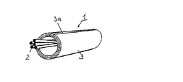
図1には、光ケーブルユニット1の部分が示されている。光ケーブルユニット1は、長手方向に溶接継目3aを備えた金属管3内に配置された光導波路2からなっている。光導波路2と金属管3の間の空隙は、充填化合物を充填して、水が長手方向に移動するのを防止する。光導波路2の数は通常6から20の間であるが、40以下であればよい。光導波路2の長さは、金属管3の長さよりも長い。光導波路の金属管を超える超過長さは、光導波路の長さの通常約0.2から0.3%である。金属管の壁厚は0.2から0.3mmであり、金属管の外径は2.5から4.0mmである。伝送ケーブルにおいてワイヤの代わりに用いられる光ケーブルユニットの上述したデータは、典型的なものである。
FIG. 1 shows a portion of the
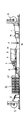
図2に示すように、テープ5が供給リール4から連続的に引き出され、そして、成形装置6に供給され、成形装置において、テープ5が長軸方向にスロットを備えた管に成形される。成形装置6の一部はトリミング用具(細部は省略)であり、テープを所望の幅に切断するために使用される。成形装置6は、数セットの成形ローラ(細部は省略)を更に備えている。スロット付管の長軸方向のスロットは、レーザ溶接装置7によって閉じられて、長手方向の継目3aを形成する(図1参照)。溶接装置7におけるスロット付管の精密な誘導は、管を囲み、エンドレスチェーンによって引っ張られる複数対の掴み具を備えた第1クランプ器8によって行われる。
As shown in FIG. 2, the
減径装置9、即ち、それによって管の径が減少する延伸装置は、第1クランプ器の下流側に位置している。第2クランプ器10は、減径装置9の下流側に位置して、管を把持し、延伸装置を通って引っ張る。第1のクランプ器8の引っ張り速度に関する第2クランプ器10の引っ張り速度は、減径装置9と第1クランプ器の間の管のゆるみの関数として制御される。駆動巻き取りリール11は、第2クランプの下流側に位置し、管はその外周の周りに数回巻きつけられる。巻き取りリール11の速度は、第2クランプ器10の巻き取り速度に等しい。保管リール12は、巻き取りリール11の後方に位置して、ケーブル1を少し緊張させながら巻き取る。
The
複数の光導波路2を供給する供給装置14は、供給リール4と成形装置6との間に位置し、その上に光導波路が巻き付けられている複数のスプール15を備えている。光導波路2はスプール15から引き取られてスロット付管の中に導かれ、その後、溶接装置7に進む。静止した(図示しない)金属チューブレットが、繊細な光導波路2を保護するために、スロット付管の中に突き出ており、その中を通って光導波路が誘導される。最も早い状態では、溶接装置7を通過した後、光導波路2が金属チューブレットから解放される。
The
金属チューブレットは(図示しない)別の金属チューブレットによって同心で囲まれている。金属管には、2つの同心金属チューブレットによって形成された環状の間隙を通って加圧下に、石油ゼリーが充填される。金属管3内の光導波路2を金属管の長さよりも長めにするために、溶接された金属管は、掴み具によって溶接された金属を把持して力を加えて変形して管の径を減ずる第2クランプ器10と巻き取りリール11との間で連続的にかつ弾性的に引っ張る、即ち、伸ばされる。これによって、巻き取りリール11が、同一長さの金属管3および光導波路2を巻き取る。巻き取りリール上では、弾性的引張りがゆるみ、その結果、金属管が短くなり通常の状態に戻り、光導波路の長さが金属管の長さよりも長くなる。
The metal tubelet is concentrically surrounded by another metal tubelet (not shown). The metal tube is filled with petroleum jelly under pressure through an annular gap formed by two concentric metal tubelets. In order to make the
弾性的引っ張りは、力Fによって生じ、溶接された金属管を第2クランプ器10と巻き取りリール11との間で一方に偏らせる。これは、金属管にぶら下げられた錘、例えば、ローラ(細部は省略)によって行われる。力F、即ち錘16によって、偏りの大きさが決まり、それによって、伸びの大きさが決まる。
力Fは、管を、錘16によるのと同一方向に偏らせるローラ(図示しない)によって生じさせても良い。
The elastic tension is generated by the force F and biases the welded metal tube to one side between the
The force F may be generated by a roller (not shown) that biases the tube in the same direction as by the
特定の構造で、且つ、金属管3の材料を選択すれば、力Fの選択によって、金属管3内の光導波路の余長を正確に形成することができる。
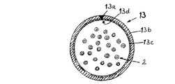
この発明によると、テープ5はオーステナイト鋼と銅の積層からなっており、溶接装置は、CO2レーザである。CO2レーザによって、金属管3のオーステナイト層13bの継目13aを溶接する。積層しているオーステナイト層の継目13aに注がれた溶接熱がオーステナイト層13bの壁厚を貫通して、銅層13cの端部を合わせて溶接する。銅層13cの溶接継目13dには、オーステナイト層13bの溶接継目13aと同様に、空隙(ボイド)がない。
If the material of the metal tube 3 is selected with a specific structure, the extra length of the optical waveguide in the metal tube 3 can be accurately formed by selecting the force F.
According to the present invention, the
この発明の好ましい態様において、積層テープの壁厚は、0.25mmである。銅層の壁厚は0.05mmである。 In a preferred embodiment of this invention, the wall thickness of the laminated tape is 0.25 mm. The wall thickness of the copper layer is 0.05 mm.
Claims (4)
第1の内側層(13c)は銅からなっており、第2の外側層(13b)はオーステナイト鋼からなっており、前記第1の内側層(13c)および第2の外側層(13b)の両方の層の前記長軸に沿った継目はレーザ溶接されており、前記両方の層の継目は重ね合わせて配置されており、そして、前記レーザ溶接はCO2レーザによって行われていることを特徴とする光ケーブルユニット。 An optical cable unit comprising a two-layer metal tube with a laser weld seam along the long axis, and at least one optical waveguide disposed inside the metal tube,
The first inner layer (13c) is made of copper, the second outer layer (13b) is made of austenitic steel, and the first inner layer (13c) and the second outer layer (13b) along seams to the long axis of both layers are laser welded, characterized in that are arranged seams superimposed of said both layers and wherein the laser welding is performed by a CO 2 laser Optical cable unit.
オーステナイト鋼の層および銅の層が積層されたテープを、連続的にスロット付管に成形し、前記スロット付管の継目をCO2レーザによって溶接して、前記オーステナイト鋼の層の継目に注がれた熱によって、前記銅の層の継目を溶接することを特徴とする光ケーブルユニットの製造方法。
Along the long axis, comprising continuously forming a metal tape into a slotted tube, continuously disposing at least one optical waveguide in an open slotted tube, and closing the slot by a laser welding unit A method of manufacturing an optical cable unit comprising a metal tube provided with a laser welding seam, and at least one optical waveguide disposed inside the metal tube,
A tape in which an austenitic steel layer and a copper layer are laminated is continuously formed into a slotted tube, a seam of the slotted tube is welded by a CO 2 laser, and the seam of the austenitic steel layer is poured. A method for manufacturing an optical cable unit, comprising welding a seam of the copper layer by the generated heat.
Applications Claiming Priority (2)
| Application Number | Priority Date | Filing Date | Title |
|---|---|---|---|
| NO20041392A NO20041392D0 (en) | 2004-04-02 | 2004-04-02 | Optical cable assembly and method of manufacture thereof |
| NO20041392 | 2004-04-02 |
Publications (2)
| Publication Number | Publication Date |
|---|---|
| JP2005292838A true JP2005292838A (en) | 2005-10-20 |
| JP4686237B2 JP4686237B2 (en) | 2011-05-25 |
Family
ID=34859245
Family Applications (1)
| Application Number | Title | Priority Date | Filing Date |
|---|---|---|---|
| JP2005106203A Expired - Fee Related JP4686237B2 (en) | 2004-04-02 | 2005-04-01 | Optical cable unit |
Country Status (5)
| Country | Link |
|---|---|
| US (1) | US7329829B2 (en) |
| EP (1) | EP1582898B1 (en) |
| JP (1) | JP4686237B2 (en) |
| AT (1) | ATE549652T1 (en) |
| NO (1) | NO20041392D0 (en) |
Cited By (1)
| Publication number | Priority date | Publication date | Assignee | Title |
|---|---|---|---|---|
| US7329829B2 (en) * | 2004-04-02 | 2008-02-12 | Nexans | Optical cable unit |
Families Citing this family (3)
| Publication number | Priority date | Publication date | Assignee | Title |
|---|---|---|---|---|
| CN106054337B (en) * | 2016-08-08 | 2022-11-22 | 中天科技海缆股份有限公司 | Production line and production process of optical unit protective layer |
| WO2020112441A1 (en) * | 2018-11-29 | 2020-06-04 | Corning Research & Development Corporation | Optical fiber cable with laser welded jacket and method of manufacturing |
| EP3887130A4 (en) | 2018-11-30 | 2022-08-24 | Corning Research & Development Corporation | Laser welding of cable jacket |
Citations (10)
| Publication number | Priority date | Publication date | Assignee | Title |
|---|---|---|---|---|
| US3183300A (en) * | 1963-02-11 | 1965-05-11 | Gen Cable Corp | Electrical cable having a laminated corrugated sheath |
| US3405228A (en) * | 1965-08-11 | 1968-10-08 | Gen Cable Corp | Folded, laminated electrical cable sheath having abutting edges of one lamination unwelded |
| US4317003A (en) * | 1980-01-17 | 1982-02-23 | Gray Stanley J | High tensile multiple sheath cable |
| JPS602909A (en) * | 1983-05-24 | 1985-01-09 | オリン・コ−ポレ−シヨン | Optical fiber communication cable and manufacture and devicethereof |
| JPS61277910A (en) * | 1985-06-03 | 1986-12-08 | Kanai Hiroyuki | Pressure resistant pipe element for optical fiber cable |
| US4751777A (en) * | 1986-09-02 | 1988-06-21 | Jpi Aquisition, Inc. | Method for making a full round bushing |
| WO1991008501A1 (en) * | 1989-12-05 | 1991-06-13 | Nkk Corporation | Apparatus for and method of manufacturing optical fiber cable covered with metal pipe |
| FR2756641A1 (en) * | 1996-12-03 | 1998-06-05 | Fileca Foptica | Optical fibre cable module mfr. machine |
| JP2001510539A (en) * | 1997-02-04 | 2001-07-31 | フェデラル・モーグル コーポレイション | Laser welded bearing and method of manufacturing the same |
| US20030146423A1 (en) * | 2000-12-27 | 2003-08-07 | Nkf Kabel B.V. | Loose fill fiber optic cable with steel jacket |
Family Cites Families (16)
| Publication number | Priority date | Publication date | Assignee | Title |
|---|---|---|---|---|
| US3643008A (en) * | 1970-10-06 | 1972-02-15 | Whitney Blake Co | Shielded cable construction providing for an internal connection to ground |
| JPS56114366A (en) * | 1980-02-15 | 1981-09-08 | Toshiba Corp | Manufacture of cooling device |
| DE3011868A1 (en) * | 1980-03-27 | 1981-10-01 | Kabel- und Metallwerke Gutehoffnungshütte AG, 3000 Hannover | HUMIDITY PROTECTED ELECTRICAL POWER CABLE |
| US4477147A (en) * | 1981-11-23 | 1984-10-16 | Olin Corporation | Method and apparatus for assembling an optical fiber communication cable |
| JPS60115381A (en) * | 1983-11-25 | 1985-06-21 | Hitachi Ltd | Joining method of different metals |
| US4852965A (en) * | 1987-02-27 | 1989-08-01 | American Telephone And Telegraph Company At&T Bell Laboratories | Composite service and distribution communications media |
| US5026967A (en) * | 1990-07-09 | 1991-06-25 | Jpi Transportation Products, Inc. | Vision enhanced method for making a full round bushing |
| DE4112354A1 (en) * | 1991-04-16 | 1992-10-22 | Behr Gmbh & Co | DEVICE FOR CATALYTIC DETOXING OF EXHAUST GAS |
| US5269056A (en) * | 1992-09-16 | 1993-12-14 | Oea, Inc. | Laser welding of wire strands to an electrode pin |
| DE4434133A1 (en) * | 1994-09-24 | 1996-03-28 | Kabelmetal Electro Gmbh | Method of manufacturing an optical cable from a metal pipe |
| DE4434134A1 (en) * | 1994-09-24 | 1996-03-28 | Kabelmetal Electro Gmbh | Process for producing a longitudinally welded metal tube |
| JP3233542B2 (en) * | 1995-02-14 | 2001-11-26 | 株式会社オーシーシー | Manufacturing method and manufacturing apparatus for metal tube coated optical fiber cable |
| US6300591B1 (en) * | 2000-03-23 | 2001-10-09 | Sandia Corporation | Method for laser welding a fin and a tube |
| FR2809645B1 (en) * | 2000-05-31 | 2002-09-27 | Air Liquide | APPLICATION OF A LASER-ARC HYBRID PROCESS TO TUBE WELDING |
| EP1184128B1 (en) * | 2000-08-31 | 2003-06-25 | Nexans | Method for the production of a metal pipe from copper |
| NO20041392D0 (en) * | 2004-04-02 | 2004-04-02 | Nexans | Optical cable assembly and method of manufacture thereof |
-
2004
- 2004-04-02 NO NO20041392A patent/NO20041392D0/en unknown
-
2005
- 2005-04-01 EP EP05300245A patent/EP1582898B1/en not_active Expired - Lifetime
- 2005-04-01 AT AT05300245T patent/ATE549652T1/en active
- 2005-04-01 JP JP2005106203A patent/JP4686237B2/en not_active Expired - Fee Related
- 2005-04-02 US US11/097,449 patent/US7329829B2/en not_active Expired - Fee Related
Patent Citations (10)
| Publication number | Priority date | Publication date | Assignee | Title |
|---|---|---|---|---|
| US3183300A (en) * | 1963-02-11 | 1965-05-11 | Gen Cable Corp | Electrical cable having a laminated corrugated sheath |
| US3405228A (en) * | 1965-08-11 | 1968-10-08 | Gen Cable Corp | Folded, laminated electrical cable sheath having abutting edges of one lamination unwelded |
| US4317003A (en) * | 1980-01-17 | 1982-02-23 | Gray Stanley J | High tensile multiple sheath cable |
| JPS602909A (en) * | 1983-05-24 | 1985-01-09 | オリン・コ−ポレ−シヨン | Optical fiber communication cable and manufacture and devicethereof |
| JPS61277910A (en) * | 1985-06-03 | 1986-12-08 | Kanai Hiroyuki | Pressure resistant pipe element for optical fiber cable |
| US4751777A (en) * | 1986-09-02 | 1988-06-21 | Jpi Aquisition, Inc. | Method for making a full round bushing |
| WO1991008501A1 (en) * | 1989-12-05 | 1991-06-13 | Nkk Corporation | Apparatus for and method of manufacturing optical fiber cable covered with metal pipe |
| FR2756641A1 (en) * | 1996-12-03 | 1998-06-05 | Fileca Foptica | Optical fibre cable module mfr. machine |
| JP2001510539A (en) * | 1997-02-04 | 2001-07-31 | フェデラル・モーグル コーポレイション | Laser welded bearing and method of manufacturing the same |
| US20030146423A1 (en) * | 2000-12-27 | 2003-08-07 | Nkf Kabel B.V. | Loose fill fiber optic cable with steel jacket |
Cited By (1)
| Publication number | Priority date | Publication date | Assignee | Title |
|---|---|---|---|---|
| US7329829B2 (en) * | 2004-04-02 | 2008-02-12 | Nexans | Optical cable unit |
Also Published As
| Publication number | Publication date |
|---|---|
| JP4686237B2 (en) | 2011-05-25 |
| ATE549652T1 (en) | 2012-03-15 |
| US20050279737A1 (en) | 2005-12-22 |
| US7329829B2 (en) | 2008-02-12 |
| NO20041392D0 (en) | 2004-04-02 |
| EP1582898A1 (en) | 2005-10-05 |
| EP1582898B1 (en) | 2012-03-14 |
Similar Documents
| Publication | Publication Date | Title |
|---|---|---|
| JP3828599B2 (en) | Manufacturing method of metal pipe welded with vertical seam | |
| US4317003A (en) | High tensile multiple sheath cable | |
| US8111960B2 (en) | Fiber optic cable systems and methods to prevent hydrogen ingress | |
| US4407065A (en) | Multiple sheath cable and method of manufacture | |
| JPH05307135A (en) | Method for manufacturing optical fiber cable element | |
| WO1991008501A1 (en) | Apparatus for and method of manufacturing optical fiber cable covered with metal pipe | |
| US5076657A (en) | Connection structure of optical fibers sealed in metal pipes and method for connecting optical fibers sealed in metal pipes | |
| JPH068923B2 (en) | Optical fiber cable and manufacturing method thereof | |
| US5768762A (en) | Method and apparatus for manufacturing an optical cable from a metal tube | |
| JP2970456B2 (en) | Manufacturing method and manufacturing apparatus for metal tube coated optical fiber cable | |
| JP4686237B2 (en) | Optical cable unit | |
| US5142763A (en) | Method for connecting optical fibers sealed in metal pipes | |
| JPS6117447A (en) | Manufacture of optical fiber cable and apparatus | |
| JPS5532053A (en) | Optical fiber submarine cable | |
| JP2950180B2 (en) | Manufacturing method and manufacturing apparatus for metal tube coated optical fiber cable | |
| US11561358B2 (en) | Method for the continuous production of optical fibre waveguide sensors mounted in a perforated metal hollow profile | |
| JP2782993B2 (en) | Apparatus and method for producing metal tube coated optical fiber cable | |
| US20240194374A1 (en) | Method of manufacturing a submarine power cable | |
| NO322118B1 (en) | Optical cable assembly | |
| JP3181551B2 (en) | Method and apparatus for manufacturing optical fiber coated with metal tube | |
| JPS6221112A (en) | Submarine optical cable | |
| JPH10319283A (en) | Optical cable | |
| JPH04345111A (en) | Method and apparatus for producing metal pipe clad optical fiber cable | |
| KR20240126827A (en) | Submarine power cable with longitudinal tape | |
| JPS602909A (en) | Optical fiber communication cable and manufacture and devicethereof |
Legal Events
| Date | Code | Title | Description |
|---|---|---|---|
| A621 | Written request for application examination |
Free format text: JAPANESE INTERMEDIATE CODE: A621 Effective date: 20080327 |
|
| RD13 | Notification of appointment of power of sub attorney |
Free format text: JAPANESE INTERMEDIATE CODE: A7433 Effective date: 20081127 |
|
| A131 | Notification of reasons for refusal |
Free format text: JAPANESE INTERMEDIATE CODE: A131 Effective date: 20100714 |
|
| A601 | Written request for extension of time |
Free format text: JAPANESE INTERMEDIATE CODE: A601 Effective date: 20100914 |
|
| A602 | Written permission of extension of time |
Free format text: JAPANESE INTERMEDIATE CODE: A602 Effective date: 20100917 |
|
| A601 | Written request for extension of time |
Free format text: JAPANESE INTERMEDIATE CODE: A601 Effective date: 20101115 |
|
| A602 | Written permission of extension of time |
Free format text: JAPANESE INTERMEDIATE CODE: A602 Effective date: 20101118 |
|
| A601 | Written request for extension of time |
Free format text: JAPANESE INTERMEDIATE CODE: A601 Effective date: 20101214 |
|
| A602 | Written permission of extension of time |
Free format text: JAPANESE INTERMEDIATE CODE: A602 Effective date: 20101217 |
|
| RD04 | Notification of resignation of power of attorney |
Free format text: JAPANESE INTERMEDIATE CODE: A7424 Effective date: 20101227 |
|
| RD04 | Notification of resignation of power of attorney |
Free format text: JAPANESE INTERMEDIATE CODE: A7424 Effective date: 20101228 |
|
| TRDD | Decision of grant or rejection written | ||
| A01 | Written decision to grant a patent or to grant a registration (utility model) |
Free format text: JAPANESE INTERMEDIATE CODE: A01 Effective date: 20110128 |
|
| A01 | Written decision to grant a patent or to grant a registration (utility model) |
Free format text: JAPANESE INTERMEDIATE CODE: A01 |
|
| A61 | First payment of annual fees (during grant procedure) |
Free format text: JAPANESE INTERMEDIATE CODE: A61 Effective date: 20110214 |
|
| FPAY | Renewal fee payment (event date is renewal date of database) |
Free format text: PAYMENT UNTIL: 20140218 Year of fee payment: 3 |
|
| R150 | Certificate of patent or registration of utility model |
Free format text: JAPANESE INTERMEDIATE CODE: R150 |
|
| LAPS | Cancellation because of no payment of annual fees |