JP2005292916A - Vending machine - Google Patents
Vending machine Download PDFInfo
- Publication number
- JP2005292916A JP2005292916A JP2004103162A JP2004103162A JP2005292916A JP 2005292916 A JP2005292916 A JP 2005292916A JP 2004103162 A JP2004103162 A JP 2004103162A JP 2004103162 A JP2004103162 A JP 2004103162A JP 2005292916 A JP2005292916 A JP 2005292916A
- Authority
- JP
- Japan
- Prior art keywords
- vending machine
- outer door
- main body
- width direction
- door
- Prior art date
- Legal status (The legal status is an assumption and is not a legal conclusion. Google has not performed a legal analysis and makes no representation as to the accuracy of the status listed.)
- Pending
Links
- 230000003014 reinforcing effect Effects 0.000 claims description 16
- 230000002787 reinforcement Effects 0.000 abstract description 4
- 230000008878 coupling Effects 0.000 abstract 2
- 238000010168 coupling process Methods 0.000 abstract 2
- 238000005859 coupling reaction Methods 0.000 abstract 2
- 238000005452 bending Methods 0.000 description 2
- 238000012423 maintenance Methods 0.000 description 2
- 230000002542 deteriorative effect Effects 0.000 description 1
- 230000000694 effects Effects 0.000 description 1
- 230000001771 impaired effect Effects 0.000 description 1
- 238000003780 insertion Methods 0.000 description 1
- 230000037431 insertion Effects 0.000 description 1
- 230000002093 peripheral effect Effects 0.000 description 1
- 238000003466 welding Methods 0.000 description 1
Images


Landscapes
- Control Of Vending Devices And Auxiliary Devices For Vending Devices (AREA)
Abstract
Description
本発明は、自動販売機本体の前面開口部を開閉する回動自在な外扉を備えた自動販売機に関するものである。 The present invention relates to a vending machine including a rotatable outer door that opens and closes a front opening of a vending machine main body.
従来、この種の自動販売機としては、前面を開口した自動販売機本体と、自動販売機本体の前面を開閉する外扉とを備え、外扉の幅方向一端側の上端を自動販売機本体の上面に取付けた支持板に回動自在に支持され、その下端を自動販売機本体の底面前端側に上方に延びるように設けられた支軸に回動自在に挿入されたものが知られている。しかしながら、この自動販売機においては、外扉の上端面と支持板との間及び外扉の下端面と自動販売機本体との間には、それぞれ隙間が設けられているため、外扉の支軸を切断工具によって切断して外扉を強制的に開放し、内部の金銭や商品を盗み出すといった不正行為を防止することができないという欠点があった。 Conventionally, this type of vending machine has a vending machine main body with an open front and an outer door that opens and closes the front of the vending machine main body, and the upper end of one end in the width direction of the outer door is the main body of the vending machine. It is known that it is rotatably supported by a support plate attached to the upper surface of the vending machine and is rotatably inserted into a support shaft provided so that its lower end extends upward to the front end side of the bottom surface of the vending machine body. Yes. However, in this vending machine, there are gaps between the upper end surface of the outer door and the support plate and between the lower end surface of the outer door and the main body of the vending machine. There is a drawback that it is impossible to prevent an illegal act such as cutting the shaft with a cutting tool to forcibly open the outer door and stealing money or goods inside.
そこで、外扉の内側の上端側及び下端側に設けられた連結軸と、自動販売機本体の内側の上端側及び下端側に固定された連結部材とをそれぞれ回動自在に連結することにより、連結軸及び連結部材を自動販売機の外部に露出させずに自動販売機本体に外扉を支持するようにしたものが知られている(例えば、特許文献1参照)。
ところで、前述のように外扉の内側に設けられた連結軸と、自動販売機本体内に設けられた連結部材とを連結したものでは、外扉と自動販売機本体の隙間を塞ぐため、外扉の背面側の外縁部から後方に延びる補強部材を設けているが、補強部材には連結部材を挿通する切り欠きが設けられているため、補強部材の強度が低下し、自動販売機本体と外扉との間の隙間から異物を挿入して外扉を変形させることによる不正行為の防止効果が損なわれるという問題点があった。 By the way, in the case where the connecting shaft provided inside the outer door and the connecting member provided in the vending machine body are connected as described above, the gap between the outer door and the vending machine body is closed. Although the reinforcing member extending backward from the outer edge portion on the back side of the door is provided, the reinforcing member is provided with a notch through which the connecting member is inserted, so that the strength of the reinforcing member is reduced, and the vending machine main body and There has been a problem in that the effect of preventing fraud by deteriorating the outer door by inserting a foreign object through the gap with the outer door is impaired.
本発明は前記問題点に鑑みてなされたものであり、その目的とするところは、外扉と自動販売機本体との隙間を塞ぐための補強部材を用いることなく不正行為を効果的に防止することのできる自動販売機を提供することにある。また、他の目的とするところは、外扉と自動販売機本体との隙間を塞ぐための補強部材を用いる場合であっても不正行為を効果的に防止することのできる自動販売機を提供することにある。 The present invention has been made in view of the above problems, and its object is to effectively prevent fraud without using a reinforcing member for closing the gap between the outer door and the vending machine body. It is to provide a vending machine that can do this. Another object of the present invention is to provide a vending machine capable of effectively preventing fraud even when a reinforcing member for closing a gap between the outer door and the main body of the vending machine is used. There is.
本発明は前記目的を達成するために、前面を開口した自動販売機本体と、自動販売機本体の前面開口部を開閉する外扉とを備え、外扉の幅方向一端側を自動販売機本体に回動自在に支持するようにした自動販売機において、前記外扉をその前後方向少なくとも一部が自動販売機本体の前面開口部内に位置するように設けるとともに、外扉の幅方向一端側と自動販売機本体内に配置した連結軸とを、外扉を開放方向に回動した際に自動販売機本体の幅方向一端側開口縁との当接を回避するように屈曲した連結部材を介して回動自在に連結している。 In order to achieve the above object, the present invention comprises a vending machine main body having an open front and an outer door that opens and closes the front opening of the vending machine main body, and the vending machine main body has one end in the width direction of the outer door. In the vending machine that is rotatably supported, the outer door is provided so that at least a part of the outer door is located in the front opening of the main body of the vending machine, and one end side in the width direction of the outer door; Via a connecting member that is bent so as to avoid contact with the opening edge of the vending machine main body in the width direction when the outer door is rotated in the opening direction. And are pivotally connected.
これにより、外扉の前後方向少なくとも一部が自動販売機の前面開口部内に位置していることから、外扉が閉鎖された状態では外扉の背面と自動販売機本体の前面との間の隙間が露出することがない。また、自動販売機本体内に配置された連結軸と外扉とを連結する連結部材が自動販売機本体の幅方向一端側開口縁との当接を回避するように屈曲していることから、連結部材が自動販売機本体に当接することなく外扉が開放される。 As a result, since at least a part of the front and rear direction of the outer door is located in the front opening of the vending machine, the outer door is closed between the back of the outer door and the front of the vending machine main body. The gap is not exposed. In addition, since the connecting member that connects the connecting shaft and the outer door arranged in the vending machine main body is bent so as to avoid contact with the opening edge on the width direction one end side of the vending machine main body, The outer door is opened without the connecting member coming into contact with the vending machine body.
また、本発明では、前面を開口した自動販売機本体と、自動販売機本体の前面開口部を開閉する外扉とを備え、外扉の幅方向一端側を自動販売機本体に回動自在に支持するとともに、外扉の幅方向一端側の背面に自動販売機本体の幅方向一端側の側面と外扉の幅方向一端側の側面との隙間を塞ぐ補強部材を設けた自動販売機において、前記外扉の幅方向一端側と自動販売機本体内に配置した連結軸とを、外扉を開放方向に回動した際に自動販売機本体の幅方向一端側開口縁との当接を回避するように屈曲した連結部材を介して回動自在に連結している。 The present invention also includes a vending machine main body having a front opening and an outer door that opens and closes the front opening of the vending machine main body, and allows one end of the outer door in the width direction to freely rotate to the vending machine main body. In the vending machine provided with a reinforcing member that supports and closes the gap between the side surface of the vending machine main body in the width direction on one side and the side surface of the outer door in the width direction on the back surface on the one end side in the width direction of the outer door, Avoid contact between the one end in the width direction of the outer door and the connecting shaft arranged in the main body of the vending machine with the opening edge on the one end in the width direction of the vending machine when the outer door is rotated in the opening direction. It connects so that it can rotate freely through the connecting member bent so.
これにより、自動販売機本体内に配置された連結軸と連結する連結部材が自動販売機本体の幅方向一端側開口縁との当接を回避するように屈曲していることから、外扉の背面側と自動販売機本体の前面との間の隙間を塞ぐための補強部材に切り欠きを設けなくとも、連結部材が自動販売機本体に当接することなく外扉が開放される。 As a result, the connecting member connected to the connecting shaft arranged in the vending machine main body is bent so as to avoid contact with the opening edge on the one end in the width direction of the vending machine main body. Even if the notch is not provided in the reinforcing member for closing the gap between the back side and the front surface of the vending machine main body, the outer door is opened without the connecting member coming into contact with the vending machine main body.
本発明によれば、外扉が閉鎖された状態では外扉の背面と自動販売機本体の前面との間の隙間が露出することがないので、外扉の背面と自動販売機本体の前面との間の隙間を塞ぐための補強部材を用いることなく不正行為を効果的に防止することができる。 According to the present invention, when the outer door is closed, a gap between the back surface of the outer door and the front surface of the vending machine body is not exposed. Unauthorized acts can be effectively prevented without using a reinforcing member for closing the gap between the two.
また、本発明によれば、外扉の背面側と自動販売機本体の前面との間の隙間を塞ぐための補強部材に切り欠きを設けなくとも連結部材が自動販売機本体に当接することなく外扉が開放されるので、不正行為を効果的に防止することができる。 Further, according to the present invention, the connecting member does not come into contact with the vending machine main body without providing a notch in the reinforcing member for closing the gap between the rear side of the outer door and the front surface of the vending machine main body. Since the outer door is opened, fraud can be effectively prevented.
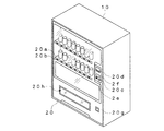
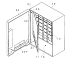
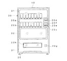
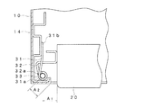
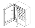
図1乃至図5は本発明の第1の実施形態を示すもので、図1は自動販売機の斜視図、図2は外扉を開放した状態を示す自動販売機の斜視図、図3は自動販売機の正面図、図4は自動販売機の要部平面図、図5は外扉を開放した状態を示す自動販売機の要部平面図である。 1 to 5 show a first embodiment of the present invention. FIG. 1 is a perspective view of a vending machine, FIG. 2 is a perspective view of the vending machine with an outer door opened, and FIG. FIG. 4 is a plan view of the main part of the vending machine, and FIG. 5 is a plan view of the main part of the vending machine showing a state in which the outer door is opened.
この自動販売機は前面を開口した自動販売機本体10と、自動販売機本体10の前面を開閉する外扉20と、自動販売機本体10及び外扉20の幅方向一端側の上端側及び下端側に設けられ、自動販売機本体10と外扉20とを連結する連結機構30とから構成されている。
The vending machine includes a
自動販売機本体10はその前面を内扉11によって開閉する断熱性の商品収納庫12と、商品収納庫12の下方に設けられた機械室13とを備え、機械室13内には図示しない冷却装置及び電装ユニットが収納されている。
The
外扉20は、自動販売機本体10の前面開口部よりも幅方向及び上下方向にやや小さく形成され、自動販売機本体10の前面の閉鎖時に自動販売機本体10の前面開口部内に位置するようになっており、その幅方向一端側を自動販売機本体10の前面側に回動自在に支持されている。また、外扉20の前面には、商品サンプル20a、商品選択スイッチ20b、硬貨投入口20c、紙幣投入口20d、返却レバー2e、金額表示部2f、硬貨返却口20g及び商品取出口20hを備えている。
The
各連結機構30は、自動販売機本体10に固定された上下一対の本体側連結部材31と、上下一対の本体側連結部材31の間に配置され、外扉20に固定された扉側連結部材32と、一対の本体側連結部材31と扉側連結部材32を回動自在に連結する連結軸33とから構成されている。
Each
本体側連結部材31は、板状部材の前端側を円筒状に曲げることにより軸受部31aが形成され、その後端側には固定片31bが設けられている。本体側連結部材31の固定片31bは、自動販売機本体10内の幅方向一端側の側面に固定された補強部材14にボルトまたは溶接により固定されている。このとき、本体側連結部材31の軸受部31aは自動販売機本体10内に位置するようになっている。
The main body
扉側連結部材32は、板状部材を断面略L字状に屈曲することにより形成され、その一端側は外扉20の側面に固定され、他端側には端部を円筒状に曲げることにより軸受部32aが形成されている。このとき、扉側連結部材32は外扉20の上端側から下端側に亘って延びるように形成されている。また、扉側連結部材32の軸受部32aの中心と外扉20の側面との距離A1 は本体側連結部材31の軸受部31aの中心と自動販売機本体10の幅方向一端側開口縁との距離A2 よりも大きく形成されている。
The door-side connecting member 32 is formed by bending a plate-like member into a substantially L-shaped cross section, one end of which is fixed to the side surface of the
連結軸33は、上下方向に延びる棒状の部材からなり、互いに上下方向に配置された一対の本体側連結部材31及び扉側連結部材32の軸受部31a,32aに連結軸33を挿通することによって、本体側連結部材31及び扉側連結部材32を回動自在に連結している。
The connecting
以上のように構成された自動販売機において、外扉20を開放すると、図5に示すように、扉側連結部材32の軸受部32aの中心と外扉20の側面との距離A1 は本体側連結部材31の軸受部31aの中心と自動販売機本体10の幅方向一端側開口縁との距離A2 よりも大きく形成されているので、自動販売機本体10の幅方向一端側開口縁と外扉20の側面が接触することはない。また、扉側連結部材32は断面L字状に形成されているので、自動販売機本体10の前面開口部の内面と扉連結部材32とが接触するまで外扉20を回動すると、自動販売機本体10の前面はほぼ完全に開放され、商品の補充等の作業を行うことが可能となる。
In the vending machine configured as described above, when the
このように、本実施形態の自動販売機によれば、前後方向少なくとも一部が自動販売機本体10の前面開口部内に位置するように外扉20を設けるとともに、外扉20を開放方向に回動した際に自動販売機本体10の幅方向一端側開口縁との当接を回避するように屈曲した扉側連結部材32を介して外扉20の幅方向一端側と自動販売機本体内10に配置した連結軸33とを連結したので、外扉20の背面と自動販売機本体10の前面との間の隙間を外部に露出させずに自動販売機本体10の前面をほぼ完全に開放することができ、外扉20の背面と自動販売機本体10の前面との間の隙間を塞ぐための扉補強部材を用いることなく不正行為を効果的に防止することができる。
As described above, according to the vending machine of the present embodiment, the
また、扉側連結部材32の軸受部32aの中心と外扉20の側面との距離A1 は本体側連結部材31の軸受部31aの中心と自動販売機本体10の幅方向一端側開口縁との距離A2 よりも大きく形成されているので、自動販売機本体10の前面はほぼ完全に開放するように外扉20を回動させることができ、メンテナンスまたは商品の補充等の作業を効率的に行うことができる。
The distance A1 between the center of the bearing portion 32a of the door side connecting member 32 and the side surface of the
また、扉側連結部材32を外扉20の上端側から下端側に亘って延びるように形成したので、外扉20の外周面と自動販売機本体10の前面開口部の間の隙間から自動販売機本体10内への異物の挿入を防止することができ、不正行為を更に効果的に防止することができる。
Further, since the door-side connecting member 32 is formed so as to extend from the upper end side to the lower end side of the
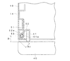
図6乃至図8は本発明の第2の実施形態を示すもので、図6は外扉を開放した状態を示す自動販売機の斜視図、図7は自動販売機の要部平面図、図8は外扉を開放した状態を示す自動販売機の要部平面図である。尚、前記第1の実施形態と同等の構成部分には同一の符号を付して示す。 FIGS. 6 to 8 show a second embodiment of the present invention. FIG. 6 is a perspective view of a vending machine in a state in which an outer door is opened. FIG. 7 is a plan view of a main part of the vending machine. 8 is a plan view of the main part of the vending machine showing a state in which the outer door is opened. In addition, the same code | symbol is attached | subjected and shown to the component equivalent to the said 1st Embodiment.
本実施形態の自動販売機は、外扉40を自動販売機本体10の前面の外形と同等に形成し、外扉40は自動販売機本体10の前面に位置するように自動販売機本体10に連結機構50によって連結され、自動販売機本体10の前面を開閉するようになっている。また、外扉40の背面側には、外縁部に沿って自動販売機本体10の前面開口部内に延出するように扉補強部材41が設けられている。
In the vending machine of the present embodiment, the
連結機構50は、本体側連結部材51と、扉側連結部材52と、連結軸53とからなり、扉側連結部材52の一端側は扉補強部材41に固定されている。扉側連結部材52の他端側は扉補強部材41の後端部から本体側連結部材51の軸受部51aに向かって延びるように形成されるとともに、端部を円筒状に曲げることにより軸受部52aが形成されている。また、扉側連結部材52の軸受部52aの中心と外扉40の背面との距離B1 は本体側連結部材51の軸受部51aの中心と自動販売機本体10の側面前端側との距離B2 よりも大きく形成されている。
The connecting
以上のように構成された自動販売機において、外扉40を開放すると、図8に示すように、扉側連結部材52の軸受部52aの中心と外扉40の背面との距離B1 は本体側連結部材51の軸受部51aの中心と自動販売機本体10の側面前端側との距離B2 よりも大きく形成されているので、自動販売機本体10の側面前端と外扉40の背面が接触することはない。また、扉側連結部材52は扉補強部材41の後端から本体側連結部材51の軸受部51aに延びるように形成されているので、自動販売機本体10の幅方向一端側開口縁と扉側連結部材52とが接触するまで外扉40を回動すると、自動販売機本体10の前面はほぼ完全に開放され、商品の補充等の作業を行うことが可能となる。
In the vending machine configured as described above, when the
このように、本実施形態の自動販売機によれば、外扉40を開放方向に回動した際に自動販売機本体10の幅方向一端側開口縁との当接を回避するように屈曲した扉側連結部材52を介して外扉40の幅方向一端側と自動販売機本体10内に配置した連結軸53とを連結したので、外扉40の背面側と自動販売機本体10の前面との間の隙間を塞ぐための扉補強部材41に切り欠きを設けることなく自動販売機本体10の前面をほぼ完全に開放することができ、不正行為を効果的に防止することができる。
Thus, according to the vending machine of the present embodiment, when the
また、扉側連結部材52の軸受部52aの中心と外扉40の背面との距離B1 は本体側連結部材51の軸受部51aの中心と自動販売機本体10の側面前端側との距離B2 よりも大きく形成されているので、自動販売機本体10の前面はほぼ完全に開放するように外扉40を回動させることができ、メンテナンスまたは商品の補充等の作業を効率的に行うことができる。
The distance B1 between the center of the bearing portion 52a of the door side connecting member 52 and the back surface of the
10…自動販売機本体、20…外扉、30…連結機構、31…本体側連結部材、32…扉側連結部材、33…連結軸、40…外扉、41…扉補強部材、50…連結機構、51…本体側連結部材、52…扉側連結部材、53…連結軸。
DESCRIPTION OF
Claims (5)
前記外扉をその前後方向少なくとも一部が自動販売機本体の前面開口部内に位置するように設けるとともに、
外扉の幅方向一端側と自動販売機本体内に配置した連結軸とを、外扉を開放方向に回動した際に自動販売機本体の幅方向一端側開口縁との当接を回避するように屈曲した連結部材を介して回動自在に連結した
ことを特徴とする自動販売機。 An automatic vending machine body that has a front opening and an outer door that opens and closes the front opening of the vending machine body, and one end in the width direction of the outer door is rotatably supported by the vending machine body. In the vending machine,
The outer door is provided so that at least a part of the front-rear direction is located in the front opening of the vending machine main body,
Avoid contact between the one end side in the width direction of the outer door and the connecting shaft disposed in the main body of the vending machine with the opening edge on one end side in the width direction of the vending machine body when the outer door is rotated in the opening direction. A vending machine characterized in that it is rotatably connected via a connecting member bent in this manner.
ことを特徴とする請求項1記載の自動販売機。 The distance from the rotation center of the connecting member with respect to the connecting shaft to the side surface on one end side in the width direction of the outer door is larger than the distance from the rotation center of the connecting member with respect to the connecting shaft to the opening edge on the one end side in the width direction of the vending machine body. The vending machine according to claim 1, wherein the vending machine is large.
ことを特徴とする請求項1または2記載の自動販売機。 The vending machine according to claim 1 or 2, wherein the connecting member is formed to extend from the upper end side to the lower end side of the outer door.
前記外扉の幅方向一端側と自動販売機本体内に配置した連結軸とを、外扉を開放方向に回動した際に自動販売機本体の幅方向一端側開口縁との当接を回避するように屈曲した連結部材を介して回動自在に連結した
ことを特徴とする自動販売機。 A vending machine main body with a front opening and an outer door that opens and closes the front opening of the vending machine main body, and one end side in the width direction of the outer door is rotatably supported by the vending machine main body. In the vending machine provided with a reinforcing member that closes the gap between the side surface on the one end side in the width direction of the vending machine main body and the side surface on the one end side in the width direction of the outer door,
Avoid contact between the one end in the width direction of the outer door and the connecting shaft arranged in the main body of the vending machine with the opening edge on the one end in the width direction of the vending machine when the outer door is rotated in the opening direction. A vending machine characterized in that it is rotatably connected via a connecting member bent in such a manner.
ことを特徴とする請求項4記載の自動販売機。
The distance from the rotation center of the connection member to the connection shaft to the back surface at one end side in the width direction of the outer door is formed larger than the distance from the rotation center of the connection member to the connection shaft to the width direction end of the vending machine body. 5. The vending machine according to claim 4, wherein
Priority Applications (1)
| Application Number | Priority Date | Filing Date | Title |
|---|---|---|---|
| JP2004103162A JP2005292916A (en) | 2004-03-31 | 2004-03-31 | Vending machine |
Applications Claiming Priority (1)
| Application Number | Priority Date | Filing Date | Title |
|---|---|---|---|
| JP2004103162A JP2005292916A (en) | 2004-03-31 | 2004-03-31 | Vending machine |
Publications (1)
| Publication Number | Publication Date |
|---|---|
| JP2005292916A true JP2005292916A (en) | 2005-10-20 |
Family
ID=35325819
Family Applications (1)
| Application Number | Title | Priority Date | Filing Date |
|---|---|---|---|
| JP2004103162A Pending JP2005292916A (en) | 2004-03-31 | 2004-03-31 | Vending machine |
Country Status (1)
| Country | Link |
|---|---|
| JP (1) | JP2005292916A (en) |
Cited By (2)
| Publication number | Priority date | Publication date | Assignee | Title |
|---|---|---|---|---|
| JP2007272344A (en) * | 2006-03-30 | 2007-10-18 | Fuji Electric Retail Systems Co Ltd | Vending machine |
| JP2023047471A (en) * | 2021-09-27 | 2023-04-06 | 富士フイルムビジネスイノベーション株式会社 | Switchgear and image forming device |
-
2004
- 2004-03-31 JP JP2004103162A patent/JP2005292916A/en active Pending
Cited By (2)
| Publication number | Priority date | Publication date | Assignee | Title |
|---|---|---|---|---|
| JP2007272344A (en) * | 2006-03-30 | 2007-10-18 | Fuji Electric Retail Systems Co Ltd | Vending machine |
| JP2023047471A (en) * | 2021-09-27 | 2023-04-06 | 富士フイルムビジネスイノベーション株式会社 | Switchgear and image forming device |
Similar Documents
| Publication | Publication Date | Title |
|---|---|---|
| US7494049B2 (en) | Shutter mechanism of automated-teller machine | |
| JP2007075487A (en) | Game machine | |
| JP5268687B2 (en) | Automatic transaction equipment | |
| JP2005292916A (en) | Vending machine | |
| JP5405961B2 (en) | Anti-theft device and anti-theft fee settlement system | |
| JP5403688B2 (en) | Game machine | |
| JP4337662B2 (en) | vending machine | |
| JP4716548B2 (en) | Automatic transaction equipment | |
| JP2010259518A (en) | Game machine | |
| JP4581799B2 (en) | vending machine | |
| JP3826255B2 (en) | Vending machine hinge device | |
| JP4938811B2 (en) | Game machine | |
| KR920010554B1 (en) | Automatic cash dispenser | |
| JP4238736B2 (en) | Vending machine door equipment | |
| JP2001307200A (en) | Automatic vending machine | |
| JP4941473B2 (en) | vending machine | |
| JP2002279482A (en) | Coin slot | |
| JP4816733B2 (en) | vending machine | |
| JP4337661B2 (en) | vending machine | |
| JP4337663B2 (en) | vending machine | |
| JP4862382B2 (en) | vending machine | |
| JP4168645B2 (en) | Vending machine door opening prevention device | |
| JP2005316915A (en) | Theft preventive structure for vending machine | |
| JP2002279503A (en) | Automatic vending machine | |
| JP4849559B2 (en) | Game machine locking device |
Legal Events
| Date | Code | Title | Description |
|---|---|---|---|
| A621 | Written request for application examination |
Free format text: JAPANESE INTERMEDIATE CODE: A621 Effective date: 20050725 |
|
| A977 | Report on retrieval |
Effective date: 20080124 Free format text: JAPANESE INTERMEDIATE CODE: A971007 |
|
| A131 | Notification of reasons for refusal |
Effective date: 20080219 Free format text: JAPANESE INTERMEDIATE CODE: A131 |
|
| A02 | Decision of refusal |
Free format text: JAPANESE INTERMEDIATE CODE: A02 Effective date: 20080708 |