JP2005293409A - Specific image position estimation apparatus, specific image position estimation method, specific image position estimation program, computer-readable recording medium recording the specific image position estimation program, and medium - Google Patents
Specific image position estimation apparatus, specific image position estimation method, specific image position estimation program, computer-readable recording medium recording the specific image position estimation program, and medium Download PDFInfo
- Publication number
- JP2005293409A JP2005293409A JP2004110116A JP2004110116A JP2005293409A JP 2005293409 A JP2005293409 A JP 2005293409A JP 2004110116 A JP2004110116 A JP 2004110116A JP 2004110116 A JP2004110116 A JP 2004110116A JP 2005293409 A JP2005293409 A JP 2005293409A
- Authority
- JP
- Japan
- Prior art keywords
- position detection
- image
- specific image
- detection point
- original image
- Prior art date
- Legal status (The legal status is an assumption and is not a legal conclusion. Google has not performed a legal analysis and makes no representation as to the accuracy of the status listed.)
- Granted
Links
Images


Classifications
-
- G—PHYSICS
- G06—COMPUTING OR CALCULATING; COUNTING
- G06T—IMAGE DATA PROCESSING OR GENERATION, IN GENERAL
- G06T7/00—Image analysis
- G06T7/70—Determining position or orientation of objects or cameras
- G06T7/73—Determining position or orientation of objects or cameras using feature-based methods
-
- G—PHYSICS
- G06—COMPUTING OR CALCULATING; COUNTING
- G06V—IMAGE OR VIDEO RECOGNITION OR UNDERSTANDING
- G06V10/00—Arrangements for image or video recognition or understanding
- G06V10/20—Image preprocessing
- G06V10/24—Aligning, centring, orientation detection or correction of the image
- G06V10/245—Aligning, centring, orientation detection or correction of the image by locating a pattern; Special marks for positioning
Landscapes
- Engineering & Computer Science (AREA)
- Physics & Mathematics (AREA)
- General Physics & Mathematics (AREA)
- Theoretical Computer Science (AREA)
- Multimedia (AREA)
- Computer Vision & Pattern Recognition (AREA)
- Image Analysis (AREA)
- Length Measuring Devices By Optical Means (AREA)
Abstract
【課題】 元画像の大きさが変化してマークの大きさが変化しても元画像中のマークを高速且つ正確に検出して元画像に含まれる特定画像の位置を確実に推定することができるようにする。
【解決手段】 2本以上の直線が1つの位置検出点で交差又は接触する位置検出マークを3つ以上付された元画像上の位置検出マークにおける位置検出点を検出する位置検出点検出手段22と、この位置検出点検出手段22により検出された位置検出点に基づいて元画像における特定画像の位置を推定する特定画像位置推定手段26とをそなえるようにする。
【選択図】 図2PROBLEM TO BE SOLVED: To reliably estimate a position of a specific image included in an original image by detecting a mark in the original image quickly and accurately even if the size of the original image changes and the size of the mark changes. It can be so.
A position detection point detection means for detecting a position detection point in a position detection mark on an original image provided with three or more position detection marks where two or more straight lines intersect or touch at one position detection point. And a specific image position estimating means 26 for estimating the position of the specific image in the original image based on the position detection points detected by the position detection point detecting means 22.
[Selection] Figure 2
Description
本発明は、画像中の特定画像の位置を推定する特定画像位置推定装置,特定画像位置推定方法,特定画像位置推定プログラム及び特定画像位置推定プログラムを記録したコンピュータ読取可能な記録媒体、並びに、特定画像の位置を推定するためのマークを付された画像を有する媒体に関する。 The present invention relates to a specific image position estimation device for estimating the position of a specific image in an image, a specific image position estimation method, a specific image position estimation program, a computer-readable recording medium recording the specific image position estimation program, and a specific The present invention relates to a medium having an image marked for estimating the position of the image.
従来から、ある画像中における特定の画像の位置を推定するために、かかる画像中にマークを埋め込むことが行なわれている。
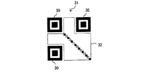
例えば、下記特許文献1には、図18に示すような正方形からなるマーク30(位置決め用シンボル)を画像31中に埋め込み、このマーク30に基づいて特定画像(ここでは2次元コード)32の位置を特定する技術が開示されている。
Conventionally, in order to estimate the position of a specific image in a certain image, a mark is embedded in the image.
For example, in
また、画像上に何らかの目的でマークを付する場合に、このマークが目立たないようにするために、画像上の白色の領域にマークを付する場合には、かかるマークを黄色にする技術が提案されている(例えば、下記特許文献2参照)。
ところで、上記特許文献1においては、画像中に付されたマーク30を検出する方法として画像を形成する画素を逐一追跡する手法を用いているが、かかる手法ではマーク30を高速に検出することが困難である。
そこで、画像中に付されたマークを高速且つ正確に検出する方法としては、かかるマークと同様の形状を有するテンプレートを画像中で走査して、このテンプレートとの一致によってかかるマークを検出する方法が考えられる。
By the way, in the above-mentioned
Therefore, as a method of detecting a mark attached to an image at high speed and accurately, there is a method of scanning a template having the same shape as the mark in the image and detecting the mark by matching with the template. Conceivable.
しかしながら、画像をカメラ等で撮像してイメージデータとして取り込んだ後に、取り込まれた画像の中からマークを検出する場合には、カメラと画像との距離(撮影距離)によって、撮像される画像の大きさや画像に付されたマークの大きさが変化する。このようにマークの大きさが変化してしまうと、かかるマークが、上記図18に示す形状であったり、或いは、図19に示すような特許文献2で用いられている三角形からなるマーク33である場合には、上述の如く大きさが変化したマークを、大きさが一定のテンプレートによって検出することは困難であり、高速且つ正確に特定画像の位置を推定することが困難になる。
However, when a mark is detected from the captured image after the image is captured by a camera or the like and captured as image data, the size of the captured image depends on the distance (capturing distance) between the camera and the image. The size of the mark added to the sheath changes. If the size of the mark changes in this way, the mark may have a shape shown in FIG. 18 or a
本発明は、このような課題に鑑み創案されたもので、元画像の大きさが変化してマークの大きさが変化しても元画像中のマークを高速且つ正確に検出して元画像に含まれる特定画像の位置を確実に推定することができる、特定画像位置推定装置,特定画像位置推定方法,特定画像位置推定プログラム及び特定画像位置推定プログラムを記録したコンピュータ読取可能な記録媒体並びに媒体を提供することを目的とする。 The present invention has been devised in view of such problems, and even if the size of the original image changes and the size of the mark changes, the mark in the original image is detected at high speed and accurately to the original image. A specific image position estimation device, a specific image position estimation method, a specific image position estimation program, a computer readable recording medium on which a specific image position estimation program is recorded, and a medium capable of reliably estimating the position of the included specific image The purpose is to provide.
上記目的を達成するために、本発明の特定画像位置推定装置は、2本以上の直線が1つの位置検出点で交差又は接触する位置検出マークを3つ以上付された元画像上の位置検出マークにおける位置検出点を検出する位置検出点検出手段と、この位置検出点検出手段により検出された位置検出点に基づいて元画像における特定画像の位置を推定する特定画像位置推定手段とをそなえたことを特徴としている(請求項1)。 In order to achieve the above object, the specific image position estimation apparatus of the present invention detects a position on an original image provided with three or more position detection marks where two or more straight lines intersect or touch at one position detection point. Position detection point detection means for detecting a position detection point in the mark, and specific image position estimation means for estimating the position of the specific image in the original image based on the position detection point detected by the position detection point detection means (Claim 1).
また、上記目的を達成するために、本発明の特定画像位置推定方法は、2本以上の直線が1つの位置検出点で交差又は接触する位置検出マークを3つ以上付された元画像上の位置検出マークにおける位置検出点を検出する位置検出点検出工程と、この位置検出点検出工程により検出された位置検出点に基づいて元画像における特定画像の位置を推定する特定画像位置推定工程とを含むことを特徴としている(請求項2)。 In order to achieve the above object, the specific image position estimation method according to the present invention is provided on an original image provided with three or more position detection marks in which two or more straight lines intersect or touch at one position detection point. A position detection point detection step for detecting a position detection point in the position detection mark, and a specific image position estimation step for estimating the position of the specific image in the original image based on the position detection point detected by the position detection point detection step. (Claim 2).
また、上記目的を達成するため、本発明の特定画像位置推定プログラムは、2本以上の直線が1つの位置検出点で交差又は接触する位置検出マークを3つ以上付された元画像上の位置検出マークにおける位置検出点を検出する位置検出点検出部、及び、位置検出点検出工程により検出された位置検出点に基づいて元画像における特定画像の位置を推定する特定画像位置推定部として、コンピュータを機能させることを特徴としている(請求項3)。 In order to achieve the above-mentioned object, the specific image position estimation program of the present invention is a position on the original image to which three or more position detection marks where two or more straight lines intersect or contact at one position detection point are attached. A computer as a position detection point detection unit for detecting a position detection point in a detection mark, and a specific image position estimation unit for estimating the position of the specific image in the original image based on the position detection point detected by the position detection point detection step Is made to function (claim 3).
なお、上記目的を達成するため、本発明のコンピュータ読取可能な記録媒体は、上記特定画像位置推定プログラムを記録したものである(請求項4)。
また、上記目的を達成するため、本発明の媒体は、位置推定対象画像である特定画像とともに、2本以上の直線が1つの位置検出点で交差又は接触する位置検出マークが3つ以上形成されていることを特徴としている(請求項5)。
In order to achieve the above object, the computer-readable recording medium of the present invention records the specific image position estimation program (claim 4).
In order to achieve the above object, the medium of the present invention is formed with three or more position detection marks in which two or more straight lines intersect or contact at one position detection point together with the specific image that is the position estimation target image. (Claim 5).
このように、本発明によれば、2本以上の直線が1つの位置検出点で交差又は接触する位置検出マークを3つ以上付された元画像から、当該元画像に含まれる特定画像の位置を推定する際に、上記1つの位置検出点を検出して、この位置検出点に基づいて特定画像の位置を推定するので、元画像の大きさが変化して位置検出マークの大きさが変化しても、高速且つ正確に元画像における特定画像の位置を検出することができる。 As described above, according to the present invention, the position of the specific image included in the original image from the original image with three or more position detection marks where two or more straight lines intersect or contact at one position detection point. Is detected, and the position of the specific image is estimated based on the position detection point. Therefore, the size of the original image changes and the size of the position detection mark changes. Even so, the position of the specific image in the original image can be detected at high speed and accurately.
以下、図面を参照しながら本発明の実施の形態について説明する。
〔1〕本発明の一実施形態について
本発明の第1実施形態としての特定画像位置推定装置及び特定画像位置推定方法について説明する。まず、本実施形態において位置推定対象である画像について説明すると、図1は本実施形態における位置推定対象画像を示す模式図である。この図1に示すように、本実施形態における位置推定対象画像1は、例えば紙や布等の媒体100上に形成され、その中に特定画像3を有して構成されている。さらに位置推定対象画像1の特定画像3の外側の四隅には、位置検出マーク2a〜2dが付されている。なお、図1では、便宜上、位置検出マーク2a〜2dを黒色で大きく示しているが、実際の位置推定対象画像としての媒体100においては、位置検出マーク2a〜2dが後述する位置検出点検出手段22には認識可能であるが、人には認識困難な色及び大きさで形成されることが望ましい。例えば、位置検出マーク2a〜2dが付される画像1上の色が白色もしくは略白色である場合には、位置検出マーク2a〜2dは黄色からなることが好ましく、また、位置検出マーク2a〜2dが付される画像1上の色が黒色もしくは略黒色である場合には、位置検出マーク2a〜2dは青色からなることが好ましい。これにより、人がこの位置検出マーク2a〜2dを視認することを困難にすることができる。
Hereinafter, embodiments of the present invention will be described with reference to the drawings.
[1] One Embodiment of the Present Invention A specific image position estimating apparatus and a specific image position estimating method as a first embodiment of the present invention will be described. First, an image that is a position estimation target in the present embodiment will be described. FIG. 1 is a schematic diagram showing a position estimation target image in the present embodiment. As shown in FIG. 1, a position
位置検出マーク2a〜2dは、少なくとも2本の直線(線分)が一つの点(位置検出点)で交差又は接触して形成されるものであり、図1に示す例においては2本の直線(線分)からなり、これら2本の直線が位置検出点Pで直交することにより形成される。従って、仮に位置検出マーク2a〜2d(以下、位置検出マーク2a〜2dを区別しない場合には、単に位置検出マーク2という)の大きさが変化しても、位置検出点Pを中心とした位置検出点P付近の形状は変化することがない、つまり、位置検出マーク2が十字形であるため、位置検出マーク2自体の大きさが変わっても十字形の中央(位置検出点P)近傍の形状は十字形のままで変化がない。従って、このような位置検出マーク2によれば、後述する位置検出点検出手段22(図2参照)によって位置検出マーク2を検出する際には、位置検出点Pを中心とした位置検出マーク2の一部を関心領域(ROI:Region Of Interest)として着目するだけで、当該位置検出マーク2を検出することができる。
The
また、上述したように位置推定対象画像(以下、単に画像ともいう)1は、その中に特定画像3を有しており、本実施形態の特定画像位置推定装置及び特定画像位置推定方法では、この特定画像3の位置を推定すべく後述するように構成されている。なお、特定画像3の全域もしくは一部には、例えば、本出願人が平成15年5月20日に出願した特許出願(特許出願番号:2003−142582)に記載された技術を用いて、画像データ(つまり視覚的な情報)とは異なる他の情報(電子透かし)が埋め込まれており、特定画像3の位置を推定して上記他の情報をデコーダにより抽出(デコード)することによって、例えば後述する〔2〕本発明の適用例欄に記載されたようなシステムを実現することができる。
Further, as described above, the position estimation target image (hereinafter also simply referred to as an image) 1 has a
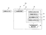
次に、本実施形態の特定画像位置推定装置について説明すると、図2は本実施形態としての特定画像位置推定装置の機能構成を示すブロック図である。この図2に示すように、本実施形態の特定画像位置推定装置101は、上記画像1を元画像として取り込むための画像読込手段10と、例えばMPU(Micro Processing Unit)もしくはCPU(Central Processing Unit)からなる演算ユニット20とをそなえて構成されている。
Next, the specific image position estimation apparatus of the present embodiment will be described. FIG. 2 is a block diagram showing a functional configuration of the specific image position estimation apparatus as the present embodiment. As shown in FIG. 2, the specific image
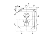
画像読込手段10は、画像1を撮像することにより画像1を演算ユニット20に取り込むものであり、例えばカメラにより構成されている。図3に画像読込手段10により撮像され演算ユニット20に取り込まれる元画像4を示す。なお、画像読込手段10により画像1(媒体100)が撮像され、演算ユニット20に取り込まれるイメージデータを以下元画像4という。
The image reading means 10 captures the
図3に示すように、画像読込手段10の画像1に対する撮影距離に応じて演算ユニット20に取り込まれる元画像4中の画像1の大きさは変化するため、撮影距離が遠くなるほど、元画像4中の画像1の大きさは小さくなる。さらに、画像読込手段10の画像1に対する撮影距離が近くなるほど、演算ユニット20に取り込む元画像4中の画像1の大きさは大きくなる。
As shown in FIG. 3, the size of the
また、図2に示すように、演算ユニット20は、元画像記憶部21,位置検出点検出手段22及び特定画像位置推定手段26をそなえて構成されている。
元画像記憶部21は、画像読込手段10が画像1を撮像することによって取得したイメージデータとしての元画像4を演算ユニット20内に取り込んで記憶するものである。
位置検出点検出手段22は、元画像記憶部21に記憶された元画像4上の位置検出マーク2における位置検出点Pを検出するものであり、元画像分割手段23,相互相関算出手段24及び位置検出点特定手段25をそなえて構成されている。
In addition, as shown in FIG. 2, the
The original
The position detection point detection means 22 detects a position detection point P in the
元画像分割手段23は、予め分かっている画像1に付された位置検出マーク2の数と大よその配置とに応じて元画像4を分割するものである。本実施形態では、画像1の四隅に位置検出マーク2a〜2dが付されているため、元画像4を幅(x)方向及び高さ(y)方向にそれぞれ2分の1に分割して元画像4を4等分した領域4a〜4d内に位置検出マーク2a〜2dがそれぞれ存在すると仮定して、元画像分割手段23が、これら位置検出マーク2a〜2dに応じて図3に示す二点鎖線で区分される4つの領域4a〜4dに元画像4を分割する。
The original image dividing means 23 divides the original image 4 in accordance with the number and position of the position detection marks 2 attached to the
相互相関算出手段24は、位置検出マーク2における位置検出点Pを含む部分と同一形状を有する関心領域としてのテンプレート24a(図4参照)を用いて、元画像分割手段23により分割された元画像4の領域4a〜4d毎に元画像4上を走査して、テンプレート24aと元画像4上における単位走査領域との相互相関を算出するものである。つまり、相互相関算出手段24は、テンプレート24aと元画像4上における単位走査領域との相互相関を算出することによりマッチングを行なうものであり、相互相関を算出することにより単位走査領域毎にテンプレート24aとの相関係数を得る。なお、図4は相互相関算出手段24で用いるテンプレート24aを示す図である。この図4に示すように、相互相関算出手段24で用いるテンプレート24aは、その中央に位置検出点Pと同一の十字形の交点が配置された、位置検出点P付近の形状と同一の形状を有して構成される。なお、相互相関算出手段24による相互相関の算出方法については、図7を参照しながら後述する。
The
位置検出点特定手段25は、相互相関算出手段24による算出結果、つまり、単位走査領域毎の相関係数に基づいて、相関係数が最も大きい値を示した単位走査領域に位置検出点Pが存在するとして、元画像分割手段23により分割された4つの領域毎に元画像4上における位置検出点Pの位置を特定するものである。
特定画像位置推定手段26は、位置検出点検出手段22の位置検出点特定手段25により特定された4つの領域毎の位置検出マーク2に基づいて、元画像4における特定画像3の位置を推定するものである。つまり、特定画像位置推定手段26は、予め設定された各位置検出マーク2a〜2d毎の特定画像3に対する相対位置に基づいて特定画像3の元画像4上での位置を特定する。
The position detection
The specific image position estimation means 26 estimates the position of the
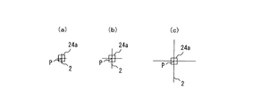
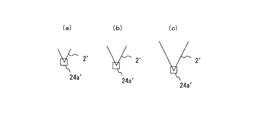
このように、本実施形態の特定画像位置推定装置101によれば、画像読込手段10により取り込まれる元画像4における画像1は、画像読込手段10の画像1に対する撮影距離に応じて大きさが変化し、その位置検出マーク2の大きさも変化する。図5(a)〜(c)にその大きさが変化した位置検出マーク2とテンプレート24aとの関係を示すと、例えばこの図5(a)〜(c)に示すように、位置検出マーク2の大きさは様々変化することになるが、位置検出マーク2が大きさが変化しても変わらない部分(即ち、位置検出点Pを中心とした部分)を一部分だけ有しており、その部分を相互相関算出手段24が関心領域(テンプレート24a)として設定するため、位置検出マーク2の大きさに関わらず、単一のテンプレート24aを用いるだけで位置検出点特定手段25が位置検出点Pの元画像4上の位置を特定することができる。
Thus, according to the specific image
つまり、位置検出マーク2の大きさが変化しても、図5(a)〜(c)に示すように、テンプレート24aの中心と位置検出点Pとが重なり合ったときに算出される相関係数が最大となるため、位置検出点検出手段22は、位置検出マーク2の大きさに関わらず位置検出マーク2の位置検出点Pを確実に検出することができる。なお、上記図18,19に示す従来からのマーク30,33でも、マーク30,33の大きさが変化しても形状が変化しない部分を有しているが、これらマーク30,33では、かかる部分が複数あるため、仮にその中で1つの部分に着目したテンプレートを走査して相互相関を算出しても、同一もしくは略同一の値が複数算出されてしまうため、着目した部分を正確に検出することはできない。
That is, even if the size of the
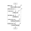
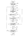
次に、本実施形態の特定画像位置推定方法(特定画像位置推定装置101の動作)について説明すると、図6は本実施形態としての特定画像位置推定方法の手順を説明するためのフローチャート(ステップS10,S20〜S23,S30)である。この図6に示すように、本実施形態の特定画像位置推定方法では、まず、画像読込工程S10において、画像読込手段10が画像1を元画像4として取り込み、元画像記憶部21が元画像4を記憶する。
Next, the specific image position estimation method (operation of the specific image position estimation apparatus 101) according to the present embodiment will be described. FIG. 6 is a flowchart for explaining the procedure of the specific image position estimation method according to the present embodiment (step S10). , S20 to S23, S30). As shown in FIG. 6, in the specific image position estimation method of the present embodiment, first, in the image reading step S10, the image reading means 10 captures the
次に元画像分割工程S21において、元画像分割手段23が位置検出マーク2の数と配置に応じて元画像4を分割(ここでは上記図3に示すように4分割)する。
そして、相互相関算出工程S22において、相互相関算出手段24が元画像分割工程S21で分割された領域毎に、位置検出マーク2における位置検出点Pを含む部分と同一形状を有するテンプレート24aを用いて元画像4上を走査して、テンプレート24aと元画像4上における単位走査領域との相互相関を算出する。
Next, in the original image dividing step S21, the original image dividing means 23 divides the original image 4 according to the number and arrangement of the position detection marks 2 (here, divided into four as shown in FIG. 3 above).
In the cross-correlation calculating step S22, the
ここで、相互相関算出工程S22での処理について、より詳細に説明すると、図7は相互相関算出工程S22の手順を説明するためのフローチャート(ステップS40〜S49)である。この図7に示すように、相互相関算出工程S22においては、相互相関算出手段24が、まず、上述のテンプレート24aを用意し、さらにこのテンプレート24aを変数T[t(u,v);u,vは図4参照]に設定する(ステップS40)。なお、ここでは、テンプレート24aの大きさを、元の画像1における位置検出マーク2よりも小さく設定している。
Here, the processing in the cross-correlation calculation step S22 will be described in more detail. FIG. 7 is a flowchart (steps S40 to S49) for explaining the procedure of the cross-correlation calculation step S22. As shown in FIG. 7, in the cross-correlation calculating step S22, the
そして、単位走査領域Iの走査開始位置を今回相互相関を算出する領域に応じて設定する。例えば、領域4aを対象とする場合を例にあげて説明すると、単位走査領域Iの位置I(x,y)をまず原点に設定すべく、yを0に設定し(ステップS41)、さらにxを0に設定する(ステップS42)。
なお、単位走査領域Iはテンプレート24aと同じ大きさであり、変数f(u+x,v+y)で表わすことができる。
Then, the scanning start position of the unit scanning region I is set according to the region where the cross correlation is calculated this time. For example, the case where the
The unit scanning area I is the same size as the
そして、相互相関算出手段24は、原点における単位走査領域Iとテンプレート24aとの相互相関を下記式(1)により算出する(ステップS43)。なお、下記式(1)において、sはテンプレート24aの定義域を表わす。
∫∫st(x,y)f(u+x,v+y)dudv ・・・(1)
次いで、相互相関算出手段24は、上記式(1)の算出結果として得られた相関係数がいままでに算出された中で最大の値であるか否かを判断する(ステップS44)。
Then, the
∫∫ s t (x, y) f (u + x, v + y) dudv ··· (1)
Next, the
ここで、今回算出された相関係数が最大であれば(ステップS44のYesルート)、総合相関算出手段24は、この今回算出された相関係数を単位走査領域Iの位置I(x,y)とともにRAM(Random Access Memory)等からなる一時格納用の記憶部に記憶する(ステップS45)。
一方、今回算出された相関係数が最大でなければ(ステップS44のNoルート)、上述したステップS45の処理をスキップして次工程(ステップS46)へ進む。
Here, if the correlation coefficient calculated this time is the maximum (Yes route in step S44), the total
On the other hand, if the correlation coefficient calculated this time is not the maximum (No route of step S44), the process of step S45 described above is skipped and the process proceeds to the next step (step S46).
次いで、相互相関算出手段24は、単位走査領域Iの位置I(x,y)をx方向(走査方向)へ1画素進めて(ステップS46)、単位走査領域Iの位置I(x,y)が元画像4上の幅方向(x方向)の1/2まで到達したか否かを判断する(ステップS47)。ここで単位走査領域Iの位置I(x,y)が、元画像4の幅方向1/2まで到達していないと判断されると(ステップS47のNoルート)、相互相関算出手段24は、上述したステップS43の処理にリターンして、単位走査領域Iの位置I(x,y)が、元画像4の幅方向1/2まで到達したと判断されるまで(ステップS47のYesルート)、上述したステップS43〜S46までの処理を繰り返し実行する。
Next, the
そして、単位走査領域Iの位置I(x,y)が、元画像4の幅方向1/2まで到達すると(ステップS47のYesルート)、相互相関算出手段24は、単位走査領域Iの位置I(x,y)をy方向(副走査方向)へ1画素進めて(ステップS48)、単位走査領域Iの位置I(x,y)が元画像4上の高さ方向(y方向)の1/2まで到達したか否かを判断する(ステップS49)。
When the position I (x, y) of the unit scanning region I reaches the
ここで、単位走査領域Iの位置I(x,y)が、元画像4の高さ方向1/2まで到達していないと判断されると(ステップS49のNoルート)、相互相関算出手段24は、上述したステップS42の処理にリターンして、単位走査領域Iの位置I(x,y)が、元画像4の高さ方向1/2まで到達したと判断されるまで(ステップS49のYesルート)、上述したステップS42〜S48までの処理を繰り返し実行する。 Here, if it is determined that the position I (x, y) of the unit scanning region I has not reached 1/2 in the height direction of the original image 4 (No route in step S49), the cross-correlation calculating means 24 Return to the process of step S42 described above until it is determined that the position I (x, y) of the unit scanning region I has reached half the height direction of the original image 4 (Yes in step S49). Route), the above-described steps S42 to S48 are repeated.
そして、単位走査領域Iの位置I(x,y)が、元画像4の高さ方向1/2まで到達すると(ステップS49のYesルート)、相互相関算出手段24は処理を終了する。
このように、相互相関算出工程S22において、相互相関算出手段24が元画像4の領域4aにおけるテンプレート24aと単位走査領域Iとの相互相関を算出する。なお、元画像4の領域4b〜4dについても、走査開始位置の設定(即ち、ステップS41,S42の処理)及び終了位置の設定が異なる以外は、同様の手順でテンプレート24aと単位走査領域Iとの相互相関が算出され、すべての領域4a〜4dについての処理が行なわれて相互相関算出工程S22の処理が終了する。
When the position I (x, y) of the unit scan region I reaches the
In this way, in the cross-correlation calculating step S22, the
そして、図6に示すように、位置検出点特定工程S23において、位置検出点特定手段25が相互相関算出工程S22での算出結果、即ち、単位走査領域毎のテンプレート24aとの相関係数に基づいて、かかる相関係数が最大の単位走査領域(ここではその単位走査領域Iの中心)に位置検出点Pが存在するとして、元画像分割工程S21で分割された領域4a〜4d毎に位置検出点Pの位置を特定する。つまり、上記図7のステップS45で記憶された相関係数が最大の単位走査領域Iの位置I(x,y)に位置検出点Pが存在するとして、各領域4a〜4d毎に位置検出点Pの位置を特定する。
As shown in FIG. 6, in the position detection point specifying step S23, the position detection
なお、ここでは、元画像分割工程S21,相互相関算出工程S22及び位置検出点特定工程S23が、元画像4上の位置検出マーク2における位置検出点Pを検出する位置検出点検出工程S20として機能する。
そして、特定画像位置推定工程S30において、位置検出点検出工程S20で検出された各領域毎(ここでは4つ)の位置検出点Pの元画像4上の位置に基づいて、特定画像位置推定手段26が、元画像4における特定画像3の位置を推定し、処理が終了される。
Here, the original image dividing step S21, the cross-correlation calculating step S22, and the position detection point specifying step S23 function as a position detection point detection step S20 for detecting the position detection point P in the
Then, in the specific image position estimation step S30, based on the position on the original image 4 of the position detection point P for each region (here, four) detected in the position detection point detection step S20, the specific image position estimation means 26 estimates the position of the
このように、本発明の一実施形態としての特定画像位置推定装置101及び特定画像位置推定方法によれば、位置検出点検出手段22が位置検出点P近傍と同一形状をテンプレート24aとして用いて画像1における位置検出マーク2を検出するため、画像読込手段10と画像1との撮影距離に応じて取り込まれる位置検出マーク2の大きさが変化しても、単一のテンプレート24aを用いて元画像4上を走査するだけで元画像4上における位置検出点Pの位置を高速且つ正確に特定することができ、この位置検出点Pに基づいて特定画像位置推定手段26が確実に画像1中の特定画像3の位置を推定することができる。
Thus, according to the specific image
さらに、元画像分割手段23により、元画像4を位置検出マーク2に応じて分割するため、一つの領域から一つの位置検出点Pを検出するだけでよくなり、一つの領域から複数の位置検出点Pを検出するよりも高精度且つ高効率に位置検出点Pを検出することができる。
Further, since the original image 4 is divided according to the
〔2〕本発明の適用例
次に、上述した本発明の一実施形態としての特定画像位置推定装置及び特定画像位置推定方法並びに媒体の適用例について説明する。
〔2−1〕第1適用例
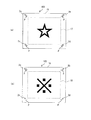
まず、第1適用例について説明すると、本発明の一実施形態としての特定画像位置推定装置及び特定画像位置推定方法並びに媒体は、例えば、図8(a),(b)に示すようなカード(媒体)102,103を用いたゲームシステム(遊戯装置)104(図9参照)に適用することができる。なお、カード102の有する画像15の特定画像17内及びカード103の有する画像16の特定画像18内には、それぞれゲーム(遊戯)に使用される特有の情報が画像データとは異なる他の情報として埋め込まれている。また、図8(a),(b)において上記図1と同符号のものは同様もしくは略同様のものを示す。
[2] Application Example of the Present Invention Next, an application example of the above-described specific image position estimation device, specific image position estimation method, and medium as an embodiment of the present invention will be described.
[2-1] First Application Example First, the first application example will be described. A specific image position estimation apparatus, a specific image position estimation method, and a medium as an embodiment of the present invention are illustrated in FIG. The present invention can be applied to a game system (game device) 104 (see FIG. 9) using cards (medium) 102 and 103 as shown in FIG. In addition, in the
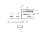
図9は上記実施形態の特定画像位置推定装置及び特定画像位置推定方法並びに媒体が適用されたゲームシステム104の構成を示すブロック図である。つまり、この図9に示すように、カメラ11,メモリ40,演算ユニット(CPU等)50,表示部60とをそなえたゲームシステム104において、カメラ11がカード102,103の画像を元画像として取り込む上述の画像読込手段10としての機能を果たすとともに、メモリ40がゲームに必要な情報を記憶するとともに元画像記憶部21として機能するように構成され、さらに、演算ユニット50が、特定画像17,18内に埋め込まれた画像データとは異なる、ゲームに使用される情報をデコードするデコーダ(遊戯情報取得手段)として機能するとともに、デコードされた情報に基づいてゲームに関する処理を行なう処理部51と、位置検出点検出手段22及び特定画像位置推定手段26とをそなえるように構成することにより、処理部51が、カード102,103のそれぞれの特定画像17,18から読み出された情報に基づいてゲームを実行することができる。
FIG. 9 is a block diagram illustrating a configuration of the
例えば、図9に示すゲームシステム104が、画像15,16のそれぞれの特定画像17,18に埋め込まれたゲームに関する情報に基づいて、カード102,103の対戦ゲームを行なうものである場合には、以下に示すような手順でゲームが行なわれる。
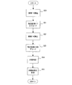
図10はゲームシステム104におけるゲームの手順を説明するためのフローチャート(ステップS50〜S55)である。この図10に示すように、まず、上記画像読込工程S10での処理と同様に、画像読込手段10としてのカメラ11がカード102の画像15(カード102)を取り込む(ステップS50)。そして、上記位置検出点検出工程S20及び特定画像位置推定工程S30での処理と同様に、演算ユニット50の位置検出点検出手段22及び特定画像推定手段26が、画像15上における特定画像17の位置を推定し、処理部51がこの特定画像17の位置に基づいて特定画像17に埋め込まれた情報をデコードする(ステップS51)。
For example, in the case where the
FIG. 10 is a flowchart (steps S50 to S55) for explaining a game procedure in the
次いで、上記画像15に対する処理(ステップS50,S51)と同様に、カード103の画像16(カード103)を取り込んで(ステップS52)、特定画像18に埋め込まれた情報をデコードする(ステップS53)。
そして、処理部51が、画像15の特定画像17からデコードされた情報と画像16の特定画像18からデコードされた情報とに基づいて、カード102,103の対戦判定(ここでは勝ち負け判定)を行なう(ステップS54)。
Next, similarly to the processing for the image 15 (steps S50 and S51), the image 16 (card 103) of the
Then, based on the information decoded from the
さらに、処理部51が、カード102,103の対戦結果を表示部60に表示させることにより(ステップS55)、本ゲームが終了される。
このように、本発明の一実施形態としての特定画像位置推定装置及び特定画像位置推定方法並びに媒体を図9に示すようなゲームシステム104に適用することができ、このゲームシステム104においても、上述した一実施形態と同様の効果を得ることができる。
Further, the
As described above, the specific image position estimation apparatus, the specific image position estimation method, and the medium according to the embodiment of the present invention can be applied to the
〔2−2〕第2適用例
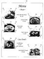
次に、第2適用例について説明すると、本発明の一実施形態としての特定画像位置推定装置及び特定画像位置推定方法並びに媒体は、物や情報等に関する取引を行なう様々な取引システム(取引装置)に適用することができる。例えば、図11に示すようなメニュー表(媒体)19を用いた注文システム(取引装置)105(図12参照)に適用することができる。なお、メニュー表19における特定画像19a〜19fには、それぞれを注文(取引)するために必要な情報や料金等の情報が埋め込まれている。また、図11において上記図1と同符号のものは同様もしくは略同様のものを示す。
[2-2] Second Application Example Next, a second application example will be described. The specific image position estimation device, the specific image position estimation method, and the medium according to an embodiment of the present invention are used for transactions relating to things, information, and the like. The present invention can be applied to various transaction systems (transaction devices) to be performed. For example, the present invention can be applied to an order system (transaction apparatus) 105 (see FIG. 12) using a menu table (medium) 19 as shown in FIG. The
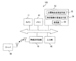
つまり、図12に示すように、カメラ11,メモリ41,演算ユニット(CPU等)52,無線送受信部70,入力部80及びサーバ90とをそなえた注文システム105において、カメラ11がメニュー表19の画像を元画像として取り込む上述の画像読込手段10としての機能を果たすとともに、メモリ41が注文に必要な情報を記憶するとともに上述した元画像記憶部21として機能するように構成され、さらに、演算ユニット52が、メニュー表19の特定画像19a〜19f内に埋め込まれた画像データとは異なる、注文に使用される情報をデコードするデコーダ(取引情報取得手段)として機能するとともに、デコードされた情報に基づいて取引にかかる処理を行なう処理部53と、上述した位置検出点検出手段22及び特定画像位置推定手段26とをそなえるように構成することにより、処理部53が、メニュー表19における特定画像19a〜19fのそれぞれから読み出された情報に基づいて無線送受信部70を用いて無線でサーバ90に対して注文を実行することができる。なお、入力部80は、例えば、注文個数や処理をキャンセルするためのものであり、ここではカメラ11と入力部80とから客がメニュー表19に基づいて注文を行なうための注文機が構成される。
That is, as shown in FIG. 12, in the
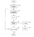
図13は図12に示す注文システム105での動作を説明するためのフローチャート(ステップS60〜S66)である。この図13に示すように、図12に示す注文システム105では、まず、注文を行なう客に対してメニュー表19及び注文機を渡し(ステップS60)、客は、この注文機のカメラ11を用いて、メニュー表19から所望のメニュー、つまり、特定画像19a〜19fのうち注文したい所望の特定画像(ここでは特定画像19aとする)を撮像することにより、特定画像19aを含む画像を元画像としてメモリ41へ取り込む(ステップS61)。
FIG. 13 is a flowchart (steps S60 to S66) for explaining the operation of the
次いで、上記位置検出点検出工程S20及び特定画像位置推定工程S30での処理と同様に、演算ユニット52の位置検出点検出手段22及び特定画像推定手段26がメニュー表19上における特定画像19aの位置を推定し、処理部53がこの特定画像19aの位置に基づいて特定画像19aに埋め込まれた情報をデコードする(ステップS62)。
そして、処理部53は、デコードされた特定画像19aに埋め込まれていた情報を無線送受信部70からサーバ90に対して発信する(ステップS63)。
Next, as in the processing in the position detection point detection step S20 and the specific image position estimation step S30, the position detection point detection means 22 and the specific image estimation means 26 of the
Then, the processing unit 53 transmits the information embedded in the decoded
なお、デコードされた情報をサーバ90へ無線発信する前に、処理部53がデコードされた情報が正しくデコードされたか否かをチェックするように構成してもよい。
次に、サーバ90は、無線送受信部70から無線発信された特定画像19aに埋め込まれていた情報を受信すると(ステップS64)、この情報に基づいて特定画像19aに関する注文を受け付ける(ステップS65)。
Note that the processing unit 53 may check whether the decoded information is correctly decoded before wirelessly transmitting the decoded information to the
Next, when the
なお、上記ステップS63での処理後、処理部53では、さらに注文を行なうか否かを判断して(ステップS66)、客がさらに注文を行なう場合には上記ステップS61の処理にリターンし(ステップS66のYesルート)、これ以上注文を行なわなければ処理を終了する(ステップS66のNoルート)。
このように、本発明の一実施形態としての特定画像位置推定装置及び特定画像位置推定方法並びに媒体を図12に示すような注文システム105に適用することができ、この取引装置としての注文システム105においても、上述した一実施形態と同様の効果を得ることができる。
After the process in step S63, the processing unit 53 determines whether or not to place an order (step S66). If the customer places an order, the process returns to the process in step S61 (step S61). If there is no more order, the process is terminated (No route in step S66).
As described above, the specific image position estimation apparatus, the specific image position estimation method, and the medium as one embodiment of the present invention can be applied to the
〔3〕その他
なお、本発明は上述した実施形態に限定されるものではなく、本発明の趣旨を逸脱しない範囲で種々変形して実施することができる。
例えば、上述した実施形態では、元画像分割工程S21において元画像分割手段23が、画像1中の位置検出マーク2に応じて元画像4を分割するように構成したが、位置検出点検出手段22が元画像分割手段23をそなえず、本発明の特定画像位置推定方法において元画像分割工程S21を省略してもよい。この場合には、例えば相互相関算出工程S22において相互相関算出手段24が、テンプレート24aと単位走査領域との相関係数が最大となるものを含み上から4番目までの大きな相関係数の単位走査領域を記憶するように構成し、位置検出点特定工程S23において位置検出点特定手段25が、これら4つの単位走査領域それぞれに位置検出点Pが存在するとして位置検出点Pの位置を特定するように構成する。
[3] Others The present invention is not limited to the above-described embodiments, and various modifications can be made without departing from the spirit of the present invention.
For example, in the above-described embodiment, the original
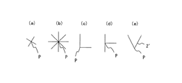
また、上述した実施形態では、画像1中に付される位置検出マーク2を上記図1に示すような形状としたが、上述したように、位置検出マークは、少なくとも2本の直線(線分)が1つの位置検出点で交差又は接触して形成されていればよく、例えば、図14(a)〜(e)に示すような形状でもよい。つまり、位置検出マークとしては、大きさが変化しても1つの位置検出点Pを中心とした付近の形状が変わらない特性をそなえていればよい。図15(a)〜(c)にその大きさが変化した位置検出マーク2′とテンプレート24aとの関係を示す。例えば、図14(e)に示すマークを位置検出マーク2′とした場合でも、図15(a)〜(c)に示すように位置検出マーク2′の大きさが様々変化しても、相互相関算出手段24が位置検出点Pを中心とした部分をテンプレート24a′として用いることにより、位置検出マーク2′の大きさに関わらず、単一のテンプレート24a′を用いるだけで位置検出点特定手段25が位置検出マーク2′の元画像4上の位置を特定することができる。
In the above-described embodiment, the
さらに、上述した実施形態では、画像1中に位置検出マーク2を4つ付したが、本発明はこれに限定されるものではなく、位置検出マーク2が3つ画像1中に付されていれば、特定領域を指定することができるため、本発明において位置検出対象画像としての媒体に付される位置検出マーク2は3つ以上であればよい。
また、上述した実施形態では、画像1中の特定画像3の外側に位置検出マーク2a〜2dを付したが、本発明はこれに限定されるものではなく、例えば、図16に示すように、位置検出マーク2a〜2dを特定画像3の内側に設けるようにしてもよい。
Furthermore, in the above-described embodiment, four position detection marks 2 are added to the
In the above-described embodiment, the position detection marks 2a to 2d are attached to the outside of the
さらに、上述した実施形態では、位置検出マーク2a〜2dがそれぞれ独立した4つの位置検出マークとして画像1中に設けられているが、本発明はこれに限定されるものではなく、例えば、図17に示すように、4つの位置検出マーク2a〜2dを直線で繋げて構成してもよく、この場合には、相互相関算出工程S22において、相互相関算出手段24がいずれかの直線を検出すると、その直線に基づいてテンプレート24aを走査する方向を決定することにより、より効率的に位置検出点Pを検出することが可能になる。つまり、位置検出マーク2を構成する直線に沿ってテンプレート24aを走査することにより、より高速に位置検出点Pを検出可能になる。
Furthermore, in the embodiment described above, the position detection marks 2a to 2d are provided in the
なお、本発明の特定画像位置推定装置において、画像読込手段10以外の何らかの手段で元画像記憶部21に元画像4が記憶されている場合には、画像読込手段10をそなえる必要はなく、位置検出点検出手段22及び特定画像位置推定手段26により、画像1中の特定画像3の位置を推定するように構成してもよい。従って、この場合には、本発明の特定画像位置推定方法において画像読込工程S10を省くことができる。
In the specific image position estimation apparatus of the present invention, when the original image 4 is stored in the original
また、上述した実施形態では、テンプレート24aと元画像4上における単位走査領域とのマッチングを、相互相関算出工程S22において相互相関算出手段24がテンプレート24aと単位走査領域との相互相関を算出することにより行なったが、本発明はこれに限定されるものではなく、テンプレート24aと元画像4上における単位走査領域とのマッチングを、相互相関を算出する方法以外の方法により行なうように構成してもよい。
In the above-described embodiment, matching between the
また、上述した元画像分割手段23,相互相関算出手段24,位置検出点特定手段25,特定画像位置推定手段26としての機能は、コンピュータ(CPU,情報処理装置,各種端末を含む)が所定のアプリケーションプログラム(特定画像位置推定プログラム)を実行することによって実現される。
そのプログラムは、例えばフレキシブルディスク,CD−ROM,CD−R,CD−RW,DVD等のコンピュータ読取可能な記録媒体に記録された形態で提供される。この場合、コンピュータはその記録媒体から特定画像位置推定プログラムを読み取って内部記憶装置または外部記憶装置に転送し格納して用いる。また、そのプログラムを、例えば磁気ディスク,光ディスク,光磁気ディスク等の記憶装置(記録媒体)に記録しておき、その記憶装置から通信回線を介してコンピュータに提供するようにしてもよい。
The functions of the original
The program is provided in a form recorded on a computer-readable recording medium such as a flexible disk, CD-ROM, CD-R, CD-RW, or DVD. In this case, the computer reads the specific image position estimation program from the recording medium, transfers it to an internal storage device or an external storage device, and uses it. Further, the program may be recorded in a storage device (recording medium) such as a magnetic disk, an optical disk, or a magneto-optical disk, and provided from the storage device to a computer via a communication line.
ここで、コンピュータとは、ハードウェアとOS(オペレーティングシステム)とを含む概念であり、OSの制御の下で動作するハードウェアを意味している。また、OSが不要でアプリケーションプログラム単独でハードウェアを動作させるような場合には、そのハードウェア自体がコンピュータに相当する。ハードウェアは、少なくとも、CPU等のマイクロプロセッサと、記録媒体に記録されたコンピュータプログラムを読み取るための手段とをそなえている。上記特定画像位置推定プログラムとしてのアプリケーションプログラムは、上述のようなコンピュータに、元画像分割手段23,相互相関算出手段24,位置検出点特定手段25,特定画像位置推定手段26としての機能を実現させるプログラムコードを含んでいる。また、その機能の一部は、アプリケーションプログラムではなくOSによって実現されてもよい。
Here, the computer is a concept including hardware and an OS (operating system) and means hardware that operates under the control of the OS. Further, when the OS is unnecessary and the hardware is operated by the application program alone, the hardware itself corresponds to the computer. The hardware includes at least a microprocessor such as a CPU and means for reading a computer program recorded on a recording medium. The application program as the specific image position estimation program causes the above-described computer to realize the functions as the original
さらに、本実施形態としての記録媒体としては、上述したフレキシブルディスク,CD−ROM,CD−R,CD−RW,DVD,磁気ディスク,光ディスク,光磁気ディスクのほか、ICカード,ROMカートリッジ,磁気テープ,パンチカード,コンピュータの内部記憶装置(RAMやROMなどのメモリ),外部記憶装置等や、バーコードなどの符号が印刷された印刷物等の、コンピュータ読取可能な種々の媒体を利用することもできる。 In addition to the above-mentioned flexible disk, CD-ROM, CD-R, CD-RW, DVD, magnetic disk, optical disk, magneto-optical disk, IC card, ROM cartridge, magnetic tape as recording media according to the present embodiment , Various types of computer-readable media such as punch cards, computer internal storage devices (memory such as RAM and ROM), external storage devices, and printed materials on which codes such as bar codes are printed. .
〔4〕付記
(付記1)
2本以上の直線が1つの位置検出点で交差又は接触する位置検出マークを3つ以上付された元画像上の該位置検出マークにおける該位置検出点を検出する位置検出点検出手段と、
該位置検出点検出手段により検出された該位置検出点に基づいて該元画像における特定画像の位置を推定する特定画像位置推定手段とをそなえたことを特徴とする、特定画像位置推定装置。
[4] Appendix (Appendix 1)
Position detection point detection means for detecting the position detection point in the position detection mark on the original image to which three or more position detection marks where two or more straight lines intersect or contact at one position detection point are attached;
A specific image position estimation device comprising: specific image position estimation means for estimating the position of a specific image in the original image based on the position detection point detected by the position detection point detection means.
(付記2)
該元画像を取り込む画像読込手段をそなえ、
該位置検出点検出手段が、該画像読込手段により取り込まれた該元画像上の該位置検出マークにおける該位置検出点を検出することを特徴とする、付記1記載の特定画像位置推定装置。
(Appendix 2)
Image reading means for capturing the original image;
The specific image position estimation apparatus according to
(付記3)
該位置検出点検出手段が、
該位置検出マークにおける該位置検出点を含む部分と同一形状を有するテンプレートを用いて該画像上を走査して、該テンプレートと該元画像上における単位走査領域との相互相関を算出する相互相関算出手段と、
該相互相関算出手段による算出結果に基づいて、該位置検出点の該元画像上の位置を特定する位置検出点特定手段とをそなえて構成されていることを特徴とする、付記1記載の特定画像位置推定装置。
(Appendix 3)
The position detection point detection means
A cross-correlation calculation that scans the image using a template having the same shape as a portion including the position detection point in the position detection mark, and calculates a cross-correlation between the template and a unit scan area on the original image Means,
The specification according to
(付記4)
該位置検出点検出手段が、
該画像上の該位置検出マークに応じて該元画像を分割する元画像分割手段をそなえ、
該相互相関算出手段が該元画像分割手段で分割された該元画像の領域毎に該相互相関を算出することを特徴とする、付記3記載の特定画像位置推定装置。
(Appendix 4)
The position detection point detection means
Comprising original image dividing means for dividing the original image in accordance with the position detection mark on the image;
4. The specific image position estimating apparatus according to
(付記5)
該元画像における該特定画像内に画像データとは異なる他の情報が埋め込まれていることを特徴とする、付記1記載の特定画像位置推定装置。
(付記6)
該位置検出マークが、該位置検出マークが付された該元画像上の色に対して人が視認困難な色であって、該位置検出点検出手段が検出可能な色からなることを特徴とする、付記1記載の特定画像位置推定装置。
(Appendix 5)
The specific image position estimating apparatus according to
(Appendix 6)
The position detection mark is a color that is difficult for a human to visually recognize the color on the original image to which the position detection mark is attached, and is made of a color that can be detected by the position detection point detection means. The specific image position estimating apparatus according to
(付記7)
2本以上の直線が1つの位置検出点で交差又は接触する位置検出マークを3つ以上付された元画像上の該位置検出マークにおける該位置検出点を検出する位置検出点検出工程と、
該位置検出点検出工程により検出された該位置検出点に基づいて該元画像における特定画像の位置を推定する特定画像位置推定工程とを含むことを特徴とする、特定画像位置推定方法。
(Appendix 7)
A position detection point detection step of detecting the position detection point in the position detection mark on the original image to which three or more position detection marks where two or more straight lines intersect or touch at one position detection point;
A specific image position estimation method comprising: a specific image position estimation step of estimating a position of a specific image in the original image based on the position detection point detected by the position detection point detection step.
(付記8)
該位置検出点検出工程が、
該位置検出マークにおける該位置検出点を含む部分と同一形状を有するテンプレートを用いて該画像上を走査して、該テンプレートと該元画像上における単位走査領域との相互相関を算出する相互相関算出工程と、
該相互相関算出工程による算出結果に基づいて、該位置検出点の該元画像上の位置を特定する位置検出点特定工程とを含むことを特徴とする、付記7記載の特定画像位置推定方法。
(Appendix 8)
The position detection point detection step includes
A cross-correlation calculation that scans the image using a template having the same shape as a portion including the position detection point in the position detection mark, and calculates a cross-correlation between the template and a unit scan area on the original image Process,
The specific image position estimation method according to appendix 7, further comprising a position detection point specifying step of specifying a position of the position detection point on the original image based on a calculation result of the cross correlation calculation step.
(付記9)
該位置検出点検出工程が、
該画像上の該位置検出マークに応じて該元画像を分割する元画像分割工程を含み、
該相互相関算出工程が該元画像分割工程で分割された該元画像の領域毎に該相互相関を算出することを特徴とする、付記8記載の特定画像位置推定方法。
(Appendix 9)
The position detection point detection step includes
An original image dividing step of dividing the original image according to the position detection mark on the image,
The specific image position estimation method according to appendix 8, wherein the cross-correlation calculating step calculates the cross-correlation for each region of the original image divided by the original image dividing step.
(付記10)
位置推定対象画像である特定画像とともに、2本以上の直線が1つの位置検出点で交差又は接触する位置検出マークが3つ以上形成されていることを特徴とする、媒体。
(付記11)
該特定画像の領域内に画像データとは異なる他の情報が埋め込まれていることを特徴とする、付記10記載の媒体。
(Appendix 10)
A medium characterized in that three or more position detection marks where two or more straight lines intersect or contact at one position detection point are formed together with a specific image which is a position estimation target image.
(Appendix 11)
The medium according to
(付記12)
該位置検出マークが、該位置検出マークが形成された領域の色に対して人が視認困難な色からなることを特徴とする、付記10記載の媒体。
(付記13)
媒体を用いて遊戯を行なう遊戯装置であって、
位置推定対象画像である特定画像をそなえ、該特定画像に画像データとは異なる該遊戯に使用される情報が埋め込まれた該媒体の画像を元画像として取り込む画像読込手段と、
該画像読込手段により取り込まれた該元画像における特定画像の位置を推定する特定画像位置推定手段と、
該特定画像位置推定手段により位置を推定された該特定画像から、上記の画像データとは異なる該遊戯に使用される情報を取得する遊戯情報取得手段と、
該遊戯情報取得手段により取得された情報に基づいて、該遊戯にかかる処理を行なう処理部とをそなえたことを特徴とする、遊戯装置。
(Appendix 12)
The medium according to
(Appendix 13)
A game device for playing using a medium,
An image reading unit that includes a specific image that is a position estimation target image, and that captures an image of the medium in which information used for the game different from image data is embedded in the specific image as an original image;
Specific image position estimating means for estimating the position of the specific image in the original image captured by the image reading means;
Game information acquisition means for acquiring information used in the game different from the image data from the specific image whose position is estimated by the specific image position estimation means;
A game apparatus comprising a processing unit that performs processing related to the game based on information acquired by the game information acquisition means.
(付記14)
媒体を用いて遊戯を行なう遊戯装置であって、
位置推定対象画像である特定画像とともに、2本以上の直線が1つの位置検出点で交差又は接触する位置検出マークを3つ以上付された該媒体の画像を元画像として取り込む画像読込手段と、
該画像読込手段により取り込まれた該元画像上の該位置検出マークにおける該位置検出点を検出する位置検出点検出手段と、
該位置検出点検出手段により検出された該位置検出点に基づいて該元画像における特定画像の位置を推定する特定画像位置推定手段と、
該特定画像位置推定手段により位置を推定された該特定画像から、該特定画像に埋め込まれた画像データとは異なる該遊戯に使用される情報を取得する遊戯情報取得手段と、
該遊戯情報取得手段により取得された情報に基づいて、該遊戯にかかる処理を行なう処理部とをそなえたことを特徴とする、遊戯装置。
(Appendix 14)
A game device for playing using a medium,
An image reading unit that captures, as an original image, an image of the medium with three or more position detection marks to which two or more straight lines intersect or contact at one position detection point together with a specific image that is a position estimation target image;
Position detection point detection means for detecting the position detection point in the position detection mark on the original image captured by the image reading means;
Specific image position estimation means for estimating the position of the specific image in the original image based on the position detection points detected by the position detection point detection means;
Game information acquisition means for acquiring information used for the game different from the image data embedded in the specific image from the specific image whose position is estimated by the specific image position estimation means;
A game apparatus comprising a processing unit that performs processing related to the game based on information acquired by the game information acquisition means.
(付記15)
遊戯に使用される媒体であって、
位置推定対象画像である特定画像をそなえるとともに、2本以上の直線が1つの位置検出点で交差又は接触する位置検出マークが3つ以上形成され、
該特定画像の領域内に画像データとは異なる該遊戯に使用される情報が埋め込まれていることを特徴とする、媒体。
(Appendix 15)
A medium used for play,
In addition to providing a specific image that is a position estimation target image, three or more position detection marks in which two or more straight lines intersect or contact at one position detection point are formed,
A medium characterized in that information used for the game different from image data is embedded in the area of the specific image.
(付記16)
媒体を用いて取引を行なう取引装置であって、
位置推定対象画像である特定画像をそなえ、該特定画像に画像データとは異なる該取引に使用される情報が埋め込まれた該媒体の画像を元画像として取り込む画像読込手段と、
該画像読込手段により取り込まれた該元画像における特定画像の位置を推定する特定画像位置推定手段と、
該特定画像位置推定手段により位置を推定された該特定画像から、上記の画像データとは異なる該取引に使用される情報を取得する取引情報取得手段と、
該取引情報取得手段により取得された情報に基づいて、該取引にかかる処理を行なう処理部とをそなえたことを特徴とする、取引装置。
(Appendix 16)
A transaction apparatus for performing a transaction using a medium,
An image reading unit that includes a specific image that is a position estimation target image and that captures an image of the medium in which information used for the transaction different from image data is embedded in the specific image as an original image;
Specific image position estimating means for estimating the position of the specific image in the original image captured by the image reading means;
Transaction information acquisition means for acquiring information used for the transaction different from the image data from the specific image whose position is estimated by the specific image position estimation means;
A transaction apparatus comprising: a processing unit that performs a process related to the transaction based on information acquired by the transaction information acquisition means.
(付記17)
媒体を用いて取引を行なう取引装置であって、
位置推定対象画像である特定画像とともに、2本以上の直線が1つの位置検出点で交差又は接触する位置検出マークを3つ以上付された該媒体の画像を元画像として取り込む画像読込手段と、
該画像読込手段により取り込まれた該元画像上の該位置検出マークにおける該位置検出点を検出する位置検出点検出手段と、
該位置検出点検出手段により検出された該位置検出点に基づいて該元画像における特定画像の位置を推定する特定画像位置推定手段と、
該特定画像位置推定手段により位置を推定された該特定画像から、該特定画像に埋め込まれた画像データとは異なる該取引に使用される情報を取得する取引情報取得手段と、
該取引情報取得手段により取得された情報に基づいて、該取引にかかる処理を行なう処理部とをそなえたことを特徴とする、取引装置。
(Appendix 17)
A transaction apparatus for performing a transaction using a medium,
An image reading means for capturing, as an original image, an image of the medium with three or more position detection marks to which two or more straight lines intersect or contact at one position detection point together with a specific image that is a position estimation target image;
Position detection point detection means for detecting the position detection point in the position detection mark on the original image captured by the image reading means;
Specific image position estimation means for estimating the position of the specific image in the original image based on the position detection points detected by the position detection point detection means;
Transaction information acquisition means for acquiring information used for the transaction different from the image data embedded in the specific image from the specific image whose position is estimated by the specific image position estimation means;
A transaction apparatus comprising: a processing unit that performs a process related to the transaction based on information acquired by the transaction information acquisition means.
(付記18)
取引に使用される媒体であって、
位置推定対象画像である特定画像をそなえるとともに、2本以上の直線が1つの位置検出点で交差又は接触する位置検出マークが3つ以上形成され、
該特定画像の領域内に画像データとは異なる該取引に使用される情報が埋め込まれていることを特徴とする、媒体。
(Appendix 18)
A medium used for trading,
In addition to providing a specific image that is a position estimation target image, three or more position detection marks in which two or more straight lines intersect or contact at one position detection point are formed,
A medium characterized in that information used for the transaction different from image data is embedded in a region of the specific image.
(付記19)
2本以上の直線が1つの位置検出点で交差又は接触する位置検出マークを3つ以上付された元画像上の該位置検出マークにおける該位置検出点を検出する位置検出点検出部、及び、
該位置検出点検出工程により検出された該位置検出点に基づいて該元画像における特定画像の位置を推定する特定画像位置推定部として、コンピュータを機能させることを特徴とする、特定画像位置推定プログラム。
(Appendix 19)
A position detection point detection unit for detecting the position detection point in the position detection mark on the original image, to which three or more position detection marks where two or more straight lines intersect or touch at one position detection point; and
A specific image position estimation program that causes a computer to function as a specific image position estimation unit that estimates the position of a specific image in the original image based on the position detection point detected by the position detection point detection step .
(付記20)
2本以上の直線が1つの位置検出点で交差又は接触する位置検出マークを3つ以上付された元画像上の該位置検出マークにおける該位置検出点を検出する位置検出点検出部、及び、
該位置検出点検出工程により検出された該位置検出点に基づいて該元画像における特定画像の位置を推定する特定画像位置推定部として、コンピュータを機能させる特定画像位置推定プログラムを記録したコンピュータ読取可能な記録媒体。
(Appendix 20)
A position detection point detection unit for detecting the position detection point in the position detection mark on the original image, to which three or more position detection marks where two or more straight lines intersect or touch at one position detection point; and
Computer-readable recording of a specific image position estimation program that causes a computer to function as a specific image position estimation unit that estimates the position of a specific image in the original image based on the position detection point detected by the position detection point detection step Recording medium.
1,15,16,31 画像
2,2a〜2d,2′ 位置検出マーク
3,17,18,19a〜19f,32 特定画像
4 元画像
4a〜4d 領域
10 画像読込手段
11 カメラ
20,50,52 演算ユニット
21 元画像記憶部
22 位置検出点検出手段
23 元画像分割手段
24 相互相関算出手段
24a,24a′ テンプレート
25 位置検出点特定手段
26 特定画像位置推定手段
30,33 マーク
40,41 メモリ
60 表示部
70 無線送受信部
80 入力部
90 サーバ
100 媒体
101 特定画像位置推定装置
102,103 カード(媒体)
104 ゲームシステム
105 注文システム
P 位置検出点
S10 画像読込工程
S20 位置検出点検出工程
S21 元画像分割工程
S22 相互相関算出工程
S23 位置検出点特定工程
S30 特定画像位置推定工程
1, 15, 16, 31
104
Claims (5)
該位置検出点検出手段により検出された該位置検出点に基づいて該元画像における特定画像の位置を推定する特定画像位置推定手段とをそなえたことを特徴とする、特定画像位置推定装置。 Position detection point detection means for detecting the position detection point in the position detection mark on the original image to which three or more position detection marks where two or more straight lines intersect or contact at one position detection point are attached;
A specific image position estimation device comprising: specific image position estimation means for estimating the position of a specific image in the original image based on the position detection point detected by the position detection point detection means.
該位置検出点検出工程により検出された該位置検出点に基づいて該元画像における特定画像の位置を推定する特定画像位置推定工程とを含むことを特徴とする、特定画像位置推定方法。 A position detection point detection step of detecting the position detection point in the position detection mark on the original image to which three or more position detection marks where two or more straight lines intersect or touch at one position detection point;
A specific image position estimation method comprising: a specific image position estimation step of estimating a position of a specific image in the original image based on the position detection point detected by the position detection point detection step.
該位置検出点検出工程により検出された該位置検出点に基づいて該元画像における特定画像の位置を推定する特定画像位置推定部として、コンピュータを機能させることを特徴とする、特定画像位置推定プログラム。 A position detection point detection unit for detecting the position detection point in the position detection mark on the original image, to which three or more position detection marks where two or more straight lines intersect or touch at one position detection point; and
A specific image position estimation program that causes a computer to function as a specific image position estimation unit that estimates the position of a specific image in the original image based on the position detection point detected by the position detection point detection step .
該位置検出点検出工程により検出された該位置検出点に基づいて該元画像における特定画像の位置を推定する特定画像位置推定部として、コンピュータを機能させる特定画像位置推定プログラムを記録したコンピュータ読取可能な記録媒体。 A position detection point detection unit for detecting the position detection point in the position detection mark on the original image, to which three or more position detection marks where two or more straight lines intersect or touch at one position detection point; and
Computer-readable recording of a specific image position estimation program that causes a computer to function as a specific image position estimation unit that estimates the position of a specific image in the original image based on the position detection point detected by the position detection point detection step Recording medium.
Priority Applications (2)
| Application Number | Priority Date | Filing Date | Title |
|---|---|---|---|
| JP2004110116A JP4576146B2 (en) | 2004-04-02 | 2004-04-02 | Specific image position estimation device |
| US10/962,512 US7477798B2 (en) | 2004-04-02 | 2004-10-13 | Specified image position estimating apparatus and method, specified image position estimating program, and specified image position estimating program recorded computer-readable recording medium, medium, game system, and transaction apparatus |
Applications Claiming Priority (1)
| Application Number | Priority Date | Filing Date | Title |
|---|---|---|---|
| JP2004110116A JP4576146B2 (en) | 2004-04-02 | 2004-04-02 | Specific image position estimation device |
Publications (2)
| Publication Number | Publication Date |
|---|---|
| JP2005293409A true JP2005293409A (en) | 2005-10-20 |
| JP4576146B2 JP4576146B2 (en) | 2010-11-04 |
Family
ID=35060634
Family Applications (1)
| Application Number | Title | Priority Date | Filing Date |
|---|---|---|---|
| JP2004110116A Expired - Lifetime JP4576146B2 (en) | 2004-04-02 | 2004-04-02 | Specific image position estimation device |
Country Status (2)
| Country | Link |
|---|---|
| US (1) | US7477798B2 (en) |
| JP (1) | JP4576146B2 (en) |
Cited By (6)
| Publication number | Priority date | Publication date | Assignee | Title |
|---|---|---|---|---|
| JP2008139125A (en) * | 2006-11-30 | 2008-06-19 | Nippon Hoso Kyokai <Nhk> | Hologram data area specifying device and hologram data area specifying program |
| JP2008242512A (en) * | 2007-03-23 | 2008-10-09 | Saxa Inc | Detection area setting device and method |
| US8422773B2 (en) | 2007-05-14 | 2013-04-16 | Fujitsu Limited | Image zone detecting using color gradation levels, method, apparatus and computer readable medium |
| JP2014053728A (en) * | 2012-09-06 | 2014-03-20 | Casio Comput Co Ltd | Image processing device and program |
| JP2014157595A (en) * | 2013-02-15 | 2014-08-28 | Fuji Xerox Co Ltd | Method and program for identifying medium or function, article including marker, and marker arrangement method |
| JP2018518770A (en) * | 2015-06-12 | 2018-07-12 | モレスキン エス.アール.エル. | A method for correcting captured images, a method for selecting a picture drawn on one or two adjacent pages of a notebook, a smartphone, a hardcover notebook, and related applications for a hardcover agenda |
Families Citing this family (9)
| Publication number | Priority date | Publication date | Assignee | Title |
|---|---|---|---|---|
| US20060072778A1 (en) * | 2004-09-28 | 2006-04-06 | Xerox Corporation. | Encoding invisible electronic information in a printed document |
| US7397584B2 (en) * | 2004-09-28 | 2008-07-08 | Xerox Corporation | Encoding invisible electronic information in a printed document |
| JP4088300B2 (en) * | 2005-06-01 | 2008-05-21 | 富士通株式会社 | Image area detection apparatus, image area detection method, and image area detection program |
| JP4801551B2 (en) * | 2006-09-27 | 2011-10-26 | 富士通株式会社 | Image area detection method, program, and apparatus |
| JP4264663B2 (en) * | 2006-11-21 | 2009-05-20 | ソニー株式会社 | Imaging apparatus, image processing apparatus, image processing method therefor, and program causing computer to execute the method |
| JP6354369B2 (en) * | 2014-06-18 | 2018-07-11 | 富士ゼロックス株式会社 | Image forming apparatus |
| JP6369190B2 (en) * | 2014-07-18 | 2018-08-08 | 富士ゼロックス株式会社 | Image forming apparatus and image position detection document |
| US9906667B2 (en) * | 2015-12-16 | 2018-02-27 | Lexmark International, Inc. | Fiducial for use in determining two media types of different lengths used on a flatbed scanner |
| WO2019084729A1 (en) * | 2017-10-30 | 2019-05-09 | Huawei Technologies Co., Ltd. | Luminance degradation estimation |
Citations (8)
| Publication number | Priority date | Publication date | Assignee | Title |
|---|---|---|---|---|
| JPH0581473A (en) * | 1991-03-19 | 1993-04-02 | T A S Tsusho Kk | Method for generating program |
| JPH06274686A (en) * | 1993-03-19 | 1994-09-30 | Mitsubishi Electric Corp | Image processing device |
| JPH07249099A (en) * | 1994-03-14 | 1995-09-26 | Fujitsu Ltd | Form identification device |
| JPH0939199A (en) * | 1995-07-31 | 1997-02-10 | Sumitomo Metal Ind Ltd | Registration mark printer, document processor and recording medium |
| JP2001224557A (en) * | 1999-09-09 | 2001-08-21 | Matsushita Electric Ind Co Ltd | Data input device, data input system, display data analysis device and medium |
| JP2002236925A (en) * | 2001-02-08 | 2002-08-23 | Torai Tec:Kk | Image inspection equipment |
| JP2002346984A (en) * | 2001-05-21 | 2002-12-04 | Printing Bureau Ministry Of Finance | Cutting system and cutting position detection method |
| JP2003317097A (en) * | 2002-04-19 | 2003-11-07 | Juki Corp | Mark recognition method and apparatus |
Family Cites Families (4)
| Publication number | Priority date | Publication date | Assignee | Title |
|---|---|---|---|---|
| JP2938338B2 (en) * | 1994-03-14 | 1999-08-23 | 株式会社デンソー | 2D code |
| JP3178305B2 (en) | 1995-06-29 | 2001-06-18 | オムロン株式会社 | Image processing method and apparatus, copier, scanner and printer equipped with the same |
| JP3178440B2 (en) | 1995-06-29 | 2001-06-18 | オムロン株式会社 | Image processing method and apparatus, copier, scanner and printer equipped with the same |
| US7503493B2 (en) * | 1999-10-25 | 2009-03-17 | Silverbrook Research Pty Ltd | Method and system for digitizing freehand graphics with user-selected properties |
-
2004
- 2004-04-02 JP JP2004110116A patent/JP4576146B2/en not_active Expired - Lifetime
- 2004-10-13 US US10/962,512 patent/US7477798B2/en active Active
Patent Citations (8)
| Publication number | Priority date | Publication date | Assignee | Title |
|---|---|---|---|---|
| JPH0581473A (en) * | 1991-03-19 | 1993-04-02 | T A S Tsusho Kk | Method for generating program |
| JPH06274686A (en) * | 1993-03-19 | 1994-09-30 | Mitsubishi Electric Corp | Image processing device |
| JPH07249099A (en) * | 1994-03-14 | 1995-09-26 | Fujitsu Ltd | Form identification device |
| JPH0939199A (en) * | 1995-07-31 | 1997-02-10 | Sumitomo Metal Ind Ltd | Registration mark printer, document processor and recording medium |
| JP2001224557A (en) * | 1999-09-09 | 2001-08-21 | Matsushita Electric Ind Co Ltd | Data input device, data input system, display data analysis device and medium |
| JP2002236925A (en) * | 2001-02-08 | 2002-08-23 | Torai Tec:Kk | Image inspection equipment |
| JP2002346984A (en) * | 2001-05-21 | 2002-12-04 | Printing Bureau Ministry Of Finance | Cutting system and cutting position detection method |
| JP2003317097A (en) * | 2002-04-19 | 2003-11-07 | Juki Corp | Mark recognition method and apparatus |
Cited By (6)
| Publication number | Priority date | Publication date | Assignee | Title |
|---|---|---|---|---|
| JP2008139125A (en) * | 2006-11-30 | 2008-06-19 | Nippon Hoso Kyokai <Nhk> | Hologram data area specifying device and hologram data area specifying program |
| JP2008242512A (en) * | 2007-03-23 | 2008-10-09 | Saxa Inc | Detection area setting device and method |
| US8422773B2 (en) | 2007-05-14 | 2013-04-16 | Fujitsu Limited | Image zone detecting using color gradation levels, method, apparatus and computer readable medium |
| JP2014053728A (en) * | 2012-09-06 | 2014-03-20 | Casio Comput Co Ltd | Image processing device and program |
| JP2014157595A (en) * | 2013-02-15 | 2014-08-28 | Fuji Xerox Co Ltd | Method and program for identifying medium or function, article including marker, and marker arrangement method |
| JP2018518770A (en) * | 2015-06-12 | 2018-07-12 | モレスキン エス.アール.エル. | A method for correcting captured images, a method for selecting a picture drawn on one or two adjacent pages of a notebook, a smartphone, a hardcover notebook, and related applications for a hardcover agenda |
Also Published As
| Publication number | Publication date |
|---|---|
| US20050226534A1 (en) | 2005-10-13 |
| JP4576146B2 (en) | 2010-11-04 |
| US7477798B2 (en) | 2009-01-13 |
Similar Documents
| Publication | Publication Date | Title |
|---|---|---|
| JP4576146B2 (en) | Specific image position estimation device | |
| JP3844482B2 (en) | Image processing device | |
| KR101285648B1 (en) | Invisible information embedding device, invisible information recognition device, invisible information embedding method, invisible information recognition method, and recording medium | |
| JP7754996B2 (en) | Game System | |
| US8641634B2 (en) | Information processing apparatus, information processing method and program | |
| US10007846B2 (en) | Image processing method | |
| JP2010157924A (en) | Subject tracking apparatus, method for controlling the same, imaging apparatus, display apparatus and program | |
| JP4364266B2 (en) | Image processing apparatus and program | |
| JP5163281B2 (en) | Vein authentication device and vein authentication method | |
| CN101661558A (en) | Image processing apparatus and image processing method, and imaging apparatus | |
| JP2010240215A (en) | Vein depth determination device, vein depth determination method and program | |
| US20070172123A1 (en) | Image processing apparatus, image processing method and computer readable medium | |
| CN101009755B (en) | Watermarked image generation apparatus and method, watermarked image analysis apparatus | |
| JP2021051806A (en) | POS terminal device and image processing method | |
| JP4182937B2 (en) | Image capturing apparatus, image processing method for image capturing apparatus, and program | |
| JP2010039912A (en) | Device and method for acquiring vein pattern, and vein template | |
| JP4675055B2 (en) | Marker processing method, marker processing apparatus, program, and recording medium | |
| JP2014071867A (en) | Image coupler, image coupling method, and program | |
| JP2007199864A (en) | Image sequence generation method and image sequence generation apparatus | |
| JPWO2005096130A1 (en) | Method and apparatus for detecting designated position of imaging apparatus, and program for detecting designated position of imaging apparatus | |
| JP6631736B1 (en) | Biometric authentication device, biometric authentication system and program | |
| JP7048347B2 (en) | Positional relationship determination device | |
| KR101896946B1 (en) | Method for detecting a trick deck | |
| TWI480080B (en) | Game doll recognition system, recognition method and game system using the same | |
| JP2016194835A (en) | Information extraction method, information extraction program and information extraction apparatus |
Legal Events
| Date | Code | Title | Description |
|---|---|---|---|
| A621 | Written request for application examination |
Free format text: JAPANESE INTERMEDIATE CODE: A621 Effective date: 20070327 |
|
| A131 | Notification of reasons for refusal |
Free format text: JAPANESE INTERMEDIATE CODE: A131 Effective date: 20091006 |
|
| A521 | Request for written amendment filed |
Free format text: JAPANESE INTERMEDIATE CODE: A523 Effective date: 20091127 |
|
| A131 | Notification of reasons for refusal |
Free format text: JAPANESE INTERMEDIATE CODE: A131 Effective date: 20100119 |
|
| A521 | Request for written amendment filed |
Free format text: JAPANESE INTERMEDIATE CODE: A523 Effective date: 20100316 |
|
| A02 | Decision of refusal |
Free format text: JAPANESE INTERMEDIATE CODE: A02 Effective date: 20100406 |
|
| A521 | Request for written amendment filed |
Free format text: JAPANESE INTERMEDIATE CODE: A523 Effective date: 20100701 |
|
| A911 | Transfer to examiner for re-examination before appeal (zenchi) |
Free format text: JAPANESE INTERMEDIATE CODE: A911 Effective date: 20100716 |
|
| TRDD | Decision of grant or rejection written | ||
| A01 | Written decision to grant a patent or to grant a registration (utility model) |
Free format text: JAPANESE INTERMEDIATE CODE: A01 Effective date: 20100810 |
|
| A01 | Written decision to grant a patent or to grant a registration (utility model) |
Free format text: JAPANESE INTERMEDIATE CODE: A01 |
|
| A61 | First payment of annual fees (during grant procedure) |
Free format text: JAPANESE INTERMEDIATE CODE: A61 Effective date: 20100823 |
|
| R150 | Certificate of patent or registration of utility model |
Ref document number: 4576146 Country of ref document: JP Free format text: JAPANESE INTERMEDIATE CODE: R150 Free format text: JAPANESE INTERMEDIATE CODE: R150 |
|
| FPAY | Renewal fee payment (event date is renewal date of database) |
Free format text: PAYMENT UNTIL: 20130827 Year of fee payment: 3 |
|
| EXPY | Cancellation because of completion of term |