JP2005293681A - Recording medium playback device and discriminating method of recording medium of the same - Google Patents

Recording medium playback device and discriminating method of recording medium of the same Download PDF

Info

Publication number
JP2005293681A
JP2005293681A JP2004104743A JP2004104743A JP2005293681A JP 2005293681 A JP2005293681 A JP 2005293681A JP 2004104743 A JP2004104743 A JP 2004104743A JP 2004104743 A JP2004104743 A JP 2004104743A JP 2005293681 A JP2005293681 A JP 2005293681A
Authority
JP
Japan
Prior art keywords
recording medium
main body
diameter
detection
disk
Prior art date
Legal status (The legal status is an assumption and is not a legal conclusion. Google has not performed a legal analysis and makes no representation as to the accuracy of the status listed.)
Pending
Application number
JP2004104743A
Other languages
Japanese (ja)
Inventor
Hideki Kinoshita
英樹 木下
Atsushi Togashi
淳 富樫
Akira Yazaki
彰 矢崎
Shigeru Kojima
滋 小島
Norio Matsuda
則夫 松田
Hitoshi Yamazaki
仁志 山崎
Current Assignee (The listed assignees may be inaccurate. Google has not performed a legal analysis and makes no representation or warranty as to the accuracy of the list.)
Pioneer Corp
Original Assignee
Pioneer Electronic Corp
Priority date (The priority date is an assumption and is not a legal conclusion. Google has not performed a legal analysis and makes no representation as to the accuracy of the date listed.)
Filing date
Publication date
Application filed by Pioneer Electronic Corp filed Critical Pioneer Electronic Corp
Priority to JP2004104743A priority Critical patent/JP2005293681A/en
Priority to US11/094,588 priority patent/US20050219965A1/en
Publication of JP2005293681A publication Critical patent/JP2005293681A/en
Pending legal-status Critical Current

Links

Images

Classifications

    • GPHYSICS
    • G11INFORMATION STORAGE
    • G11BINFORMATION STORAGE BASED ON RELATIVE MOVEMENT BETWEEN RECORD CARRIER AND TRANSDUCER
    • G11B19/00Driving, starting, stopping record carriers not specifically of filamentary or web form, or of supports therefor; Control thereof; Control of operating function ; Driving both disc and head
    • G11B19/02Control of operating function, e.g. switching from recording to reproducing
    • G11B19/12Control of operating function, e.g. switching from recording to reproducing by sensing distinguishing features of or on records, e.g. diameter end mark
    • G11B19/124Control of operating function, e.g. switching from recording to reproducing by sensing distinguishing features of or on records, e.g. diameter end mark involving the detection of diameter of disks
    • GPHYSICS
    • G11INFORMATION STORAGE
    • G11BINFORMATION STORAGE BASED ON RELATIVE MOVEMENT BETWEEN RECORD CARRIER AND TRANSDUCER
    • G11B17/00Guiding record carriers not specifically of filamentary or web form, or of supports therefor
    • G11B17/02Details
    • G11B17/04Feeding or guiding single record carrier to or from transducer unit
    • G11B17/0401Details
    • G11B17/0402Servo control
    • G11B17/0404Servo control with parallel drive rollers
    • GPHYSICS
    • G11INFORMATION STORAGE
    • G11BINFORMATION STORAGE BASED ON RELATIVE MOVEMENT BETWEEN RECORD CARRIER AND TRANSDUCER
    • G11B17/00Guiding record carriers not specifically of filamentary or web form, or of supports therefor
    • G11B17/02Details
    • G11B17/04Feeding or guiding single record carrier to or from transducer unit
    • G11B17/05Feeding or guiding single record carrier to or from transducer unit specially adapted for discs not contained within cartridges
    • G11B17/051Direct insertion, i.e. without external loading means
    • G11B17/0515Direct insertion, i.e. without external loading means adapted for discs of different sizes
    • GPHYSICS
    • G11INFORMATION STORAGE
    • G11BINFORMATION STORAGE BASED ON RELATIVE MOVEMENT BETWEEN RECORD CARRIER AND TRANSDUCER
    • G11B7/00Recording or reproducing by optical means, e.g. recording using a thermal beam of optical radiation by modifying optical properties or the physical structure, reproducing using an optical beam at lower power by sensing optical properties; Record carriers therefor
    • G11B2007/0003Recording, reproducing or erasing systems characterised by the structure or type of the carrier
    • G11B2007/0006Recording, reproducing or erasing systems characterised by the structure or type of the carrier adapted for scanning different types of carrier, e.g. CD & DVD

Landscapes

  • Feeding And Guiding Record Carriers (AREA)

Abstract

<P>PROBLEM TO BE SOLVED: To provide a recording medium playback device in which an irregular shaped recording medium and a disk-shaped recording medium are discriminated so that the irregular shaped recording medium is ejected from the inside of the device main body before the irregular shaped recording medium is inserted into the device main body. <P>SOLUTION: A CD player 1 is provided with an equipment main body 5, a conveying unit 6 and a detecting/discriminating unit 7. The conveying unit 6 conveys large and small diameter CDs into the equipment main body 5. The detecting/discriminating unit 7 is provided with a pair of detection pins 10, a pair of displacement sensors 11 and a CPU14 or the like. The pair of detection pins 10 is arranged along a width direction X of the equipment main body 5 in a mutually freely approaching and separating manner so that the pins 10 are brought into contact with outer edges of large and small diameter CDs that are inserted into the equipment main body 5. The displacement sensors 11 provide outputs to the CPU14 which detects displacement of a detection pin 12. On the basis of the information from the displacement sensors 11, the CPU14 discriminates which CD is inserted into the main body 5 among large and small diameter CDs and a card type CD as the irregular shaped recording medium. <P>COPYRIGHT: (C)2006,JPO&NCIPI

Description

本発明は、自動車などに搭載される記録媒体再生装置に関し、更に詳しくは、例えば、外径が12cm又は8cmのCompact Diskなどのディスク形記録媒体から情報を読み出す記録媒体再生装置に関する。   The present invention relates to a recording medium reproducing apparatus mounted on an automobile or the like, and more particularly to a recording medium reproducing apparatus that reads information from a disk type recording medium such as a Compact Disk having an outer diameter of 12 cm or 8 cm.

コンパクトディスク(以下、CDと記す)などの記録媒体を収容し、この記録媒体から情報を読み出す記録媒体再生装置が用いられている(例えば、特許文献1,2,3,4参照)。この種の記録媒体再生装置は、例えば、自動車などに搭載されるとともに、機器本体と、搬送ユニットと、再生ユニットとを備えている。   2. Description of the Related Art Recording medium playback apparatuses that store recording media such as compact discs (hereinafter referred to as CDs) and read information from the recording media are used (see, for example, Patent Documents 1, 2, 3, and 4). This type of recording medium playback apparatus is mounted on, for example, an automobile, and includes a device main body, a transport unit, and a playback unit.

機器本体は、扁平な箱状に形成されている。機器本体には、前述した記録媒体を出し入れする挿入口が設けられている。搬送ユニットは、前記挿入口を通して、記録媒体を機器本体内に出し入れする。再生ユニットは、搬送ユニットにより機器本体内に収容された記録媒体の情報を読み出す。   The device body is formed in a flat box shape. The apparatus main body is provided with an insertion port for taking in and out the recording medium described above. The transport unit takes the recording medium into and out of the apparatus main body through the insertion port. The reproduction unit reads information on the recording medium accommodated in the apparatus main body by the transport unit.

前述した構成の記録媒体再生装置は、例えば、外径が12cmの大径ディスク形記録媒体又は外径が8cmの小径ディスク形記録媒体が挿入されて、これらのディスク形記録媒体の情報を読み出す。
特開平11−176069号公報 特開2002−42399号公報 特開2003−338112号公報 特開2002−313007号公報
In the recording medium reproducing apparatus having the above-described configuration, for example, a large-diameter disk-type recording medium having an outer diameter of 12 cm or a small-diameter disk-type recording medium having an outer diameter of 8 cm is inserted, and information on these disk-shaped recording media is read.
JP-A-11-176069 JP 2002-42399 A JP 2003-338112 A JP 2002-313007 A

近年、記録媒体として、前述した大径ディスク形記録媒体と小径ディスク形記録媒体との他に、例えば、平面形状が矩形状のカード形記録媒体や、平面形状が小判形(樽形ともいう)のカード形記録媒体などの異形記録媒体が用いられるようになってきた。なお、小判形のカード形記録媒体は、円板状のディスク形記録媒体の両端が切り落とされた格好になっている。   In recent years, as a recording medium, in addition to the above-described large-diameter disk-shaped recording medium and small-diameter disk-shaped recording medium, for example, a card-shaped recording medium having a rectangular planar shape or an oval (also referred to as a barrel) planar shape. Different-type recording media such as card-type recording media have come to be used. Note that the oval card-type recording medium has a shape in which both ends of a disk-shaped disk-type recording medium are cut off.

前述した記録媒体再生装置は、異形記録媒体が機器本体に挿入されてしまうが、挿入された異形記録媒体を位置決めすることができずに、該異形記録媒体から情報を読み出すことができない。また、前述した記録媒体再生装置は、異形記録媒体を機器本体内から排出することも困難となる。したがって、記録媒体再生装置は、平面形状が円板状とは異なる形状の異形記録媒体と、平面形状が円板状のディスク形記録媒体とを判別することが望まれているとともに、異形ディスクが機器本体に挿入される前にこの異形ディスクを機器本体内から排出できることが望まれている。   In the above-described recording medium reproducing apparatus, the irregularly shaped recording medium is inserted into the apparatus main body, but the inserted irregularly shaped recording medium cannot be positioned and information cannot be read from the irregularly shaped recording medium. In addition, it is difficult for the above-described recording medium reproducing apparatus to eject the irregularly shaped recording medium from the apparatus main body. Therefore, it is desired that the recording medium reproducing apparatus discriminates between a deformed recording medium whose planar shape is different from a disk shape and a disc-shaped recording medium whose planar shape is a disk shape. It is desired that this deformed disk can be ejected from the inside of the equipment body before being inserted into the equipment body.

本発明の目的は、例えば、異形記録媒体と平面形状が円板状のディスク形記録媒体とを判別して、異形記録媒体が機器本体に挿入される前にこの異形記録媒体を機器本体内から排出できる記録媒体再生装置と、異形記録媒体と平面形状が円板状のディスク形記録媒体とを判別できる記録媒体の判別方法を提供することにある。   An object of the present invention is, for example, to discriminate between a deformed recording medium and a disc-shaped recording medium having a disk-like planar shape, and remove the deformed recording medium from the apparatus main body before the deformed recording medium is inserted into the apparatus main body. It is an object of the present invention to provide a recording medium reproducing apparatus capable of ejecting, a recording medium discriminating method capable of discriminating between a deformed recording medium and a disc-shaped recording medium having a disk-like planar shape.

前記課題を解決し目的を達成するために、請求項1に記載の本発明の記録媒体再生装置は、互いに外径の異なる大径ディスク形記録媒体と小径ディスク形記録媒体とを機器本体に収容して、これらのディスク形記録媒体に記録された情報を読み出す記録媒体再生装置において、互いに接離自在に設けられかつ互いに近づく方向に付勢されているとともに、前記大径ディスク形記録媒体が機器本体内に挿入される際に双方とも該大径ディスク形記録媒体の外縁に接触して互いに離れる方向に移動し、前記小径ディスク形記録媒体が機器本体内に挿入される際に少なくとも一方が該小径ディスク形記録媒体の外縁に接触して互いに離れる方向に移動する一対の検出ピンと、前記検出ピンの前記接離方向に沿った変位を検出する検出手段と、前記機器本体内に記録媒体を導く搬送手段と、前記検出手段が検出した前記一対の検出ピンの変位に基づいて、機器本体内に挿入された記録媒体が前記大径ディスク形記録媒体と前記小径ディスク形記録媒体とこれらのディスク形記録媒体とは外形の異なる異形記録媒体とのうち何れか一つであるかを判定し、機器本体内に挿入された記録媒体が前記異形記録媒体であると判定した際に前記搬送手段に前記記録媒体を前記機器本体内から排出させる判定手段と、を備えたことを特徴としている。   In order to solve the above-mentioned problems and achieve the object, the recording medium reproducing apparatus of the present invention according to claim 1 accommodates a large-diameter disk-type recording medium and a small-diameter disk-type recording medium having different outer diameters in the apparatus main body. In the recording medium reproducing apparatus for reading the information recorded on these disk-shaped recording media, the large-diameter disk-shaped recording medium is provided in such a manner as to be detachable from each other and biased toward each other. When inserted into the main body, both of them move in a direction away from each other in contact with the outer edge of the large-diameter disk-shaped recording medium, and when the small-diameter disk-shaped recording medium is inserted into the apparatus main body, A pair of detection pins that move away from each other in contact with the outer edge of the small-diameter disk-type recording medium; detection means for detecting displacement of the detection pins along the contact / separation direction; Based on the displacement of the pair of detection pins detected by the detecting means detected by the conveying means for guiding the recording medium into the main body, the recording medium inserted into the apparatus main body is the large diameter disk type recording medium and the small diameter disk type. It was determined whether the recording medium and these disc-shaped recording media are any one of the irregular-shaped recording media having different external shapes, and it was determined that the recording medium inserted into the apparatus main body was the irregular-shaped recording medium And determining means for causing the conveying means to eject the recording medium from the inside of the apparatus main body.

前記課題を解決し目的を達成するために、請求項7に記載の本発明の記録媒体再生装置
の記録媒体の判別方法は、互いに外径の異なる大径ディスク形記録媒体と小径ディスク形記録媒体とを機器本体に収容して、これらのディスク形記録媒体に記録された情報を読み出す記録媒体再生装置の記録媒体の判別方法において、前記記録媒体再生装置が、互いに接離自在に設けられかつ互いに近づく方向に付勢されているとともに、前記大径ディスク形記録媒体が機器本体内に挿入される際に双方とも該大径ディスク形記録媒体の外縁に接触して互いに離れる方向に移動し、前記小径ディスク形記録媒体が機器本体内に挿入される際に少なくとも一方が該小径ディスク形記録媒体の外縁に接触して互いに離れる方向に移動する一対の検出ピンと、前記検出ピンの前記接離方向に沿った変位を検出する検出手段と、を備え、前記検出手段が検出した前記一対の検出ピン間の最大距離から前記記録媒体の外径を判定する外径判定ステップと、前記挿入された記録媒体の外縁に当接して離間方向に移動した前記検出ピンが近づく際の変化率から前記記録媒体の形状を判定する形状判定ステップとを含んだことを特徴としている。
In order to solve the above-mentioned problems and achieve the object, the method for discriminating the recording medium of the recording medium reproducing apparatus according to the present invention is a large-diameter disk-type recording medium and a small-diameter disk-type recording medium having different outer diameters. In the recording medium discriminating method of the recording medium reproducing apparatus for reading out information recorded on these disc-shaped recording media, the recording medium reproducing apparatuses are provided so as to be able to come in contact with each other and And when the large-diameter disk-shaped recording medium is inserted into the apparatus body, both of them are in contact with the outer edge of the large-diameter disk-shaped recording medium and move away from each other, When a small-diameter disk-shaped recording medium is inserted into the apparatus main body, a pair of detection pins, at least one of which contacts the outer edge of the small-diameter disk-shaped recording medium and moves away from each other, and a front An outer diameter determining step for determining an outer diameter of the recording medium from a maximum distance between the pair of detection pins detected by the detection means. And a shape determining step for determining the shape of the recording medium from the rate of change when the detection pin that has moved in the separation direction comes into contact with the outer edge of the inserted recording medium.

以下、本発明の一実施形態にかかる記録媒体再生装置を説明する。本発明の一実施形態にかかる記録媒体再生装置の判定手段は、機器本体内に挿入される記録媒体の外縁に接触して、この記録媒体から押圧されることで互いに接離する一対の検出ピンの変位に基づいて、機器本体内に挿入された記録媒体が円板状であるか否かを判定する。こうすることで、異形記録媒体と平面形状が円板状のディスク形記録媒体とを判別できるようにしている。   A recording medium playback apparatus according to an embodiment of the present invention will be described below. The determination means of the recording medium playback apparatus according to one embodiment of the present invention is a pair of detection pins that come into contact with and separate from each other by being pressed from the recording medium by contacting the outer edge of the recording medium inserted into the apparatus main body. Based on this displacement, it is determined whether or not the recording medium inserted into the device body is disc-shaped. By doing so, it is possible to discriminate between the irregular-shaped recording medium and the disc-shaped recording medium having a disk-like planar shape.

また、判定手段は、機器本体内に挿入された記録媒体が異形記録媒体であると判別した際に、搬送手段に記録媒体を排出させる。こうすることで、異形記録媒体が機器本体に挿入される前にこの異形記録媒体を機器本体内から排出できるようにしている。   In addition, when the determination unit determines that the recording medium inserted into the apparatus main body is an irregular recording medium, the determination unit causes the conveying unit to eject the recording medium. In this way, the irregular recording medium can be ejected from the apparatus main body before the irregular recording medium is inserted into the apparatus main body.

また、本発明は、判定手段が、記録媒体を対称形であるか否かを判定する対称判定部と、記録媒体の外径を判定する外径判定部と記録媒体の形状を判定する形状判定部を有する第1ディスク判定部と、を備えても良い。   Further, the present invention provides a symmetry determination unit for determining whether or not the recording medium is symmetrical, an outer diameter determination unit for determining the outer diameter of the recording medium, and a shape determination for determining the shape of the recording medium. A first disc determination unit having a unit.

さらに、本発明は、対称判定部が記録媒体を対称形でないと判定すると、記録媒体の外径と形状を判別する第2ディスク判定部を備えても良い。   Furthermore, the present invention may include a second disc determination unit that determines the outer diameter and shape of the recording medium when the symmetry determining unit determines that the recording medium is not symmetrical.

また、本発明の記録媒体の判別方法は、記録媒体が対称形であるか否かを判定する対称判定ステップと、記録媒体の外径を判定する外径判定ステップと、記録媒体の形状を判定する形状判定ステップと、を含んでも良い。   Further, the recording medium discrimination method of the present invention includes a symmetry determining step for determining whether or not the recording medium is symmetric, an outer diameter determining step for determining the outer diameter of the recording medium, and a shape of the recording medium. And a shape determining step.

さらに、本発明の記録媒体の判別方法は、対称判定ステップで記録媒体を対称形でないと判定すると、記録媒体の外径と形状を判別する第2ディスク判定ステップを含んでも良い。   Furthermore, the recording medium determination method of the present invention may include a second disc determination step of determining the outer diameter and shape of the recording medium when it is determined in the symmetry determination step that the recording medium is not symmetrical.

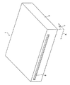
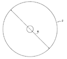
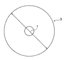
以下、本発明の一実施例にかかる記録媒体再生装置の一例としてのCDプレーヤ1を、図1ないし図20に基づいて説明する。図1などに示すCDプレーヤ1は、例えば、移動体としての自動車のインストルメントパネル(以下、インパネと呼ぶ)に装着される。CDプレーヤ1は、図2に示す大径ディスク形記録媒体としての大径CD2と、図3に示す小径ディスク形記録媒体としての小径CD3とが選択的に後述の機器本体5内に挿入される。CDプレーヤ1は、これらCD2,3に記録された情報を読み出して、音声として出力する。   A CD player 1 as an example of a recording medium playback apparatus according to an embodiment of the present invention will be described below with reference to FIGS. A CD player 1 shown in FIG. 1 and the like is mounted on, for example, an instrument panel (hereinafter referred to as an instrument panel) of an automobile as a moving body. In the CD player 1, a large-diameter CD2 as a large-diameter disk-shaped recording medium shown in FIG. 2 and a small-diameter CD3 as a small-diameter disk-shaped recording medium shown in FIG. . The CD player 1 reads the information recorded on these CDs 2 and 3 and outputs it as sound.

CD2,3は、勿論、薄手の円板状即ちディスク状に形成されており、コンピュータなどの電子機器で読みとることのできる情報を記録したディスク形記録媒体である。本実施例では、大径CD2の外径Rは、120mm(12cm)であり、小径CD3の外径rは、80mm(8cm)である。   The CDs 2 and 3 are, of course, thin discs, that is, discs, and are disc-shaped recording media on which information that can be read by an electronic device such as a computer is recorded. In this embodiment, the outer diameter R of the large diameter CD2 is 120 mm (12 cm), and the outer diameter r of the small diameter CD3 is 80 mm (8 cm).

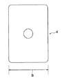
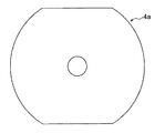
また、CDプレーヤ1は、図4に示すカード形CD4を後述の機器本体5内に収容することを阻止する。図4に示すカード形CD4は、平面形状が矩形状に形成されている。カード形CD4の短辺の長さBは、前述した小径CD3の外径rより短い。なお、短辺とは、カード形CD4の外縁の短い方の辺である。なお、カード形CD4は、本明細書に記した異形記録媒体をなしている。則ち、本明細書に記した異形記録媒体とは、平面形状が円板状とは異なる形状の記録媒体全てを示している。   Further, the CD player 1 prevents the card-type CD 4 shown in FIG. The card shape CD4 shown in FIG. 4 has a rectangular planar shape. The short side length B of the card type CD4 is shorter than the outer diameter r of the small diameter CD3 described above. The short side is the shorter side of the outer edge of the card type CD4. The card type CD4 is a variant recording medium described in this specification. In other words, the irregular-shaped recording medium described in this specification indicates all recording media having a planar shape different from the disk shape.

CDプレーヤ1は、図6に示すように、機器本体5(図1に示す)と、搬送手段としての搬送ユニット6と、再生手段としての図示しない再生ユニットと、検出・判別手段としての検出・判別ユニット7と、を備えている。なお、以下、図1中の矢印XをCDプレーヤ1の幅方向と記し、矢印YをCDプレーヤ1の奥行き方向と記し、矢印ZをCDプレーヤ1の厚み方向と記す。   As shown in FIG. 6, the CD player 1 includes a device main body 5 (shown in FIG. 1), a transport unit 6 as transport means, a playback unit (not shown) as playback means, and detection / discrimination means as detection / discrimination means. And a determination unit 7. In the following, the arrow X in FIG. 1 is referred to as the width direction of the CD player 1, the arrow Y is referred to as the depth direction of the CD player 1, and the arrow Z is referred to as the thickness direction of the CD player 1.

機器本体5は、扁平な箱状に形成されている。機器本体5には、CD2,3を機器本体5内に出し入れする挿入口8が設けられている。挿入口8は、勿論、機器本体5の内外を連通している。また、機器本体5には、CDプレーヤ1の各種の操作を行うための図示しない操作スイッチや、CDプレーヤ1の駆動状況などを表示するLCD(Liquid Crystal Display)などを備えた図示しない表示パネルが設けられている。   The device body 5 is formed in a flat box shape. The device body 5 is provided with an insertion port 8 through which the CDs 2 and 3 are inserted into and removed from the device body 5. Of course, the insertion port 8 communicates the inside and outside of the device body 5. Further, the device body 5 has a display panel (not shown) provided with an operation switch (not shown) for performing various operations of the CD player 1 and an LCD (Liquid Crystal Display) for displaying the driving status of the CD player 1 and the like. Is provided.

搬送ユニット6は、図6に示すように、駆動源としてのモータ9と、ローラ20とを備えている。モータ9は、機器本体5内に収容されており、この機器本体5に取り付けられている。   As shown in FIG. 6, the transport unit 6 includes a motor 9 as a drive source and a roller 20. The motor 9 is accommodated in the device main body 5 and attached to the device main body 5.

ローラ20は、挿入口8の近傍に配され、機器本体5などに軸芯周りに回転自在に支持されている。ローラ20の軸芯即ち長手方向は、CDプレーヤ1の幅方向X則ち挿入口8の長手方向に沿っている。ローラ20は、外周面に挿入口8内を通されるCD2,3,4が接触する。ローラ20は、モータ9により、軸芯周りに回転される。ローラ20の外周面にCD2が接触し、ローラ20がモータ9により回転駆動されることで、搬送ユニット4は、挿入口8内にCD2,3,4を通して、該CD2,3,4を機器本体5に出し入れする。こうして、搬送ユニット4は、機器本体5内にCD2,3,4を導く。   The roller 20 is disposed in the vicinity of the insertion port 8 and is supported by the device main body 5 and the like so as to be rotatable around the axis. The axial center, that is, the longitudinal direction of the roller 20 is along the width direction X of the CD player 1, that is, the longitudinal direction of the insertion slot 8. The roller 20 is in contact with CDs 2, 3 and 4 passed through the insertion port 8 on the outer peripheral surface. The roller 20 is rotated around the axis by the motor 9. When the CD 2 comes into contact with the outer peripheral surface of the roller 20 and the roller 20 is rotationally driven by the motor 9, the transport unit 4 passes the CD 2, 3, 4 through the CD 2, 3, 4 into the device main body. 5 in and out. Thus, the transport unit 4 guides the CDs 2, 3, 4 into the device body 5.

再生ユニットは、機器本体5内に収容されているとともに、機器本体5内に挿入された大径CD2と小径CD3を位置決めして、これらのCD2,3をクランプする。そして、これらのCD2,3を回転するとともに、これらのCD2,3の所定の位置の情報記録面の情報を読み出して、音声情報として出力する。   The reproduction unit is accommodated in the apparatus main body 5 and positions the large diameter CD2 and the small diameter CD3 inserted into the apparatus main body 5 to clamp these CDs 2 and 3. Then, the CDs 2 and 3 are rotated, and information on the information recording surface at a predetermined position of the CDs 2 and 3 is read and output as audio information.

検出・判別ユニット7は、図6に示すように、図示しない挿入検出器と、一対の検出ピン10と、検出手段としての一対の変位センサ11と、ディスク検出器12と、記憶手段としてのROM13と、判定手段としてのCPU14を備えている。   As shown in FIG. 6, the detection / discrimination unit 7 includes an unillustrated insertion detector, a pair of detection pins 10, a pair of displacement sensors 11 as detection means, a disk detector 12, and a ROM 13 as storage means. And a CPU 14 as determination means.

挿入検出器は、例えば、周知のLD(Laser Diode)や周知のPD(Photodiode)などを備え、前述した挿入口8の近傍でかつ機器本体5内に収容されている。LDは、レーザ光を出射する。PDは、LDからのレーザ光を受光する。挿入検出器は、挿入口8内に物体が通されると、LDからのレーザ光が遮られることで、挿入口8内に物体が通されたこと則ち機器本体5内に物体が挿入されたことを検出する。挿入検出器は、挿入口8内に物体が通されたこと則ち機器本体5内に物体が挿入されたことを示す情報を、判定手段としてのCPUなどに向けて出力する。   The insertion detector includes, for example, a well-known LD (Laser Diode), a well-known PD (Photodiode), and the like, and is housed in the apparatus main body 5 in the vicinity of the insertion port 8 described above. The LD emits laser light. The PD receives the laser light from the LD. When an object passes through the insertion port 8, the insertion detector blocks the laser beam from the LD so that the object passes through the insertion port 8. Detect that. The insertion detector outputs information indicating that an object has passed through the insertion port 8, that is, an object inserted into the device main body 5, to a CPU or the like as a determination unit.

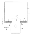
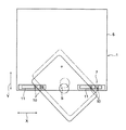
検出ピン10は、挿入口8の近傍に配され、機器本体5内に収容されている。検出ピン10は、互いに、挿入口8の長手方向則ち機器本体5の幅方向Xに沿って間隔をあけて配されている。検出ピン10は、機器本体5の底壁若しくは天井壁から立設した格好に配されている。また、検出ピン10は、挿入口8の長手方向則ち機器本体5の幅方向Xに沿って移動自在に設けられており、図示しないコイルばねなどの付勢手段により、互いに近づく方向に付勢されている。則ち、一対の検出ピン10は、互いに接離自在に設けられている。なお、接離とは、互いに近づいたり離れることをいう。   The detection pin 10 is disposed in the vicinity of the insertion port 8 and is accommodated in the device main body 5. The detection pins 10 are arranged at intervals along the longitudinal direction of the insertion port 8, that is, along the width direction X of the device body 5. The detection pins 10 are arranged so as to stand upright from the bottom wall or ceiling wall of the device body 5. Further, the detection pins 10 are provided so as to be movable along the longitudinal direction of the insertion port 8, that is, the width direction X of the device body 5, and are urged toward each other by a biasing means such as a coil spring (not shown). Has been. In other words, the pair of detection pins 10 are provided so as to be able to contact and separate from each other. In addition, contact / separation means approaching or separating from each other.

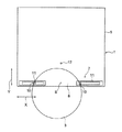
一対の検出ピン10は、挿入口8内に大径CD2が通される際に、図9ないし図11に示すように、この大径CD2の外縁が双方に接触する位置に配されている。そして、一対の検出ピン10双方は、大径CD2から押圧されて、前述した付勢手段の付勢力に抗して、一旦互いに離れた後、大径CD2の中央部が機器本体5内に挿入されると、再度互いに近づく。   When the large diameter CD2 is passed through the insertion port 8, the pair of detection pins 10 are arranged at positions where the outer edges of the large diameter CD2 come into contact with both as shown in FIGS. Then, both of the pair of detection pins 10 are pressed from the large diameter CD 2 and once separated from each other against the urging force of the urging means described above, and then the central portion of the large diameter CD 2 is inserted into the apparatus main body 5. When approached, they will approach each other again.

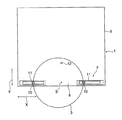
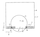
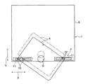
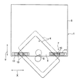
一対の検出ピン10は、挿入口8内に小径CD3が通される際に、図12ないし図14に示すように、この小径CD3の外縁が双方に接触したり、図15中の実線及び二点鎖線で示すように、一方のみに小径CD3の外縁が接触する位置に配されている。このように、一対の検出ピン10は、少なくとも一方が挿入口8を通して機器本体5に挿入される小径CD3と接触する位置に配されている。また、一対の検出ピン10は、小径CD3が挿入される際も、少なくとも一方がこの小径CD3の外縁に接触して、小径CD3から押圧されて、前述した付勢手段の付勢力に抗して一旦互いに離れた後、小径CD3の中央部が機器本体5内に挿入されると、再度互いに近づく。   As shown in FIGS. 12 to 14, when the small diameter CD3 is passed through the insertion port 8, the pair of detection pins 10 come into contact with the outer edges of the small diameter CD3, or the solid lines and two lines in FIG. As indicated by the dotted line, the outer edge of the small-diameter CD3 is disposed on only one side. Thus, at least one of the pair of detection pins 10 is disposed at a position where it comes into contact with the small-diameter CD 3 inserted into the device main body 5 through the insertion port 8. Further, when the small-diameter CD3 is inserted, at least one of the pair of detection pins 10 contacts the outer edge of the small-diameter CD3 and is pressed from the small-diameter CD3 to resist the urging force of the urging means described above. Once separated from each other, when the central portion of the small-diameter CD 3 is inserted into the device main body 5, they approach each other again.

一対の変位センサ11には、それぞれ、検出ピン10が取り付けられている。変位センサ11は、機器本体5の幅方向X則ち挿入口8の長手方向に沿った検出ピン10の変位を検出する。則ち、変位センサ11は、一対の検出ピン10の接離方向に沿ったこれらの検出ピン10の変位を検出する。図示例では、変位センサ11は、互いに最も近づいた一対の検出ピン10間の中央Sからの各検出ピン10までの距離を示す情報を、前述した検出ピン10の変位を示す情報として、判定手段としてのCPU14に向かって出力する。   A detection pin 10 is attached to each of the pair of displacement sensors 11. The displacement sensor 11 detects the displacement of the detection pin 10 along the width direction X of the device body 5, that is, the longitudinal direction of the insertion port 8. That is, the displacement sensor 11 detects the displacement of these detection pins 10 along the contact / separation direction of the pair of detection pins 10. In the illustrated example, the displacement sensor 11 uses the information indicating the distance from the center S between the pair of detection pins 10 closest to each other to the detection pins 10 as information indicating the displacement of the detection pins 10 described above. Is output to the CPU 14.

前述した変位センサ11として、従来より周知の可変抵抗器、磁気抵抗素子、マグネスケール、光電素子を用いた変位センサ等を用いても良い。変位センサ11として、スイッチを前記検出ピン10の移動方向則ち機器本体5の幅方向に沿って複数並べ、前述した検出ピン10の位置に応じてオンするスイッチを切り換えることで検出ピン10の位置則ち変位を検出するものを用いても良い。   As the displacement sensor 11 described above, a conventionally known variable resistor, magnetoresistive element, magnescale, photoelectric sensor or other displacement sensor may be used. As the displacement sensor 11, a plurality of switches are arranged along the movement direction of the detection pin 10, that is, along the width direction of the device body 5, and the position of the detection pin 10 is switched by switching the switch that is turned on according to the position of the detection pin 10 described above. That is, a device that detects displacement may be used.

ディスク検出器12は、例えば、周知のLD(Laser Diode)や周知のPD(Photodiode)などを備え、前述した挿入口8の近傍でかつ機器本体5内に収容されている。LDは、レーザ光を出射する。PDは、LDからのレーザ光を受光する。ディスク検出器12は、前述した一対の検出ピン10間の中央Sと前述した機器本体5の奥行き方向Yに沿って並ぶ位置に配されている。   The disk detector 12 includes, for example, a well-known LD (Laser Diode), a well-known PD (Photodiode), and the like, and is accommodated in the apparatus main body 5 in the vicinity of the insertion port 8 described above. The LD emits laser light. The PD receives the laser light from the LD. The disk detectors 12 are arranged at positions along the center S between the pair of detection pins 10 described above and the depth direction Y of the device main body 5 described above.

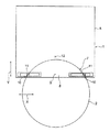
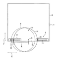
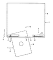
ディスク検出器12は、大径CD2と小径CD3の中央部が一対の検出ピン10間に位置付けられた後、これら一対の検出ピン10が互いに近づく際に、前述したCD2,3によりLDからPDに向かう光が遮られる位置に配されている。また、ディスク検出器12は、図19に示すように、機器本体5内に挿入されたカード形CD4などの異形記録媒体が一方の検出ピン10のみに接触し、この一方の検出ピン10が他方の検出ピン10から一旦離れた後、再度他方の検出ピン10に近づき始める際に、LDからの光をPDが受光できる位置則ちLDからPDに向かう光がカード形CD4に遮られない位置に配されている。さらに、ディスク検出器12は、図20中の実線で示す位置から二点鎖線で示す位置に向かう機器本体5内に挿入されたカード形CD4などの異形記録媒体が双方の検出ピン10に接触し、これら双方の検出ピン10を互いに離した後、再度互いに近づき始める際に、LDからPDに向かう光をカード形CD4が遮ることが可能な位置に配されている。   After the center portions of the large diameter CD2 and the small diameter CD3 are positioned between the pair of detection pins 10, the disk detector 12 is moved from the LD to the PD by the above-described CD2, 3 when the pair of detection pins 10 approach each other. It is placed at a position where the light coming from it is blocked. In the disk detector 12, as shown in FIG. 19, a deformed recording medium such as a card-shaped CD4 inserted into the device main body 5 contacts only one detection pin 10, and the one detection pin 10 is in contact with the other. When the sensor pin 10 is once separated from the detection pin 10 and starts to approach the other detection pin 10 again, the PD can receive the light from the LD, that is, the light from the LD toward the PD is not blocked by the card CD4. It is arranged. Further, in the disk detector 12, a deformed recording medium such as a card type CD 4 inserted into the device main body 5 from the position indicated by the solid line in FIG. 20 to the position indicated by the two-dot chain line contacts both the detection pins 10. When the two detection pins 10 are separated from each other and then start to approach each other again, the card-shaped CD 4 is arranged at a position where the light from the LD toward the PD can be blocked.

ディスク検出器12は、前述したようにCD2,3によりLDからPDに向かう光が遮られることで、挿入口8内にCD2,3が通されたこと則ち機器本体5内にCD2,3が挿入されたことを検出する。ディスク検出器12は、挿入口8内にCD2,3が通されたこと則ち機器本体5内にCD2,3が挿入されたことを示す情報を、判定手段としてのCPU14などに向けて出力する。   As described above, the disk detector 12 blocks the light from the LD toward the PD by the CDs 2 and 3, so that the CDs 2 and 3 are passed through the insertion port 8. Detects insertion. The disc detector 12 outputs information indicating that the CDs 2 and 3 have been inserted into the insertion port 8, that is, the CDs 2 and 3 into the device body 5 to the CPU 14 as a determination unit. .

ROM13は、CDプレーヤ1を動作されるためのプログラムなどを記憶している。ROM13は、CPU14を後述するように動作されるためのプログラムを記憶している。   The ROM 13 stores a program for operating the CD player 1 and the like. The ROM 13 stores a program for operating the CPU 14 as described later.

CPU14は、図6に示すように、対称判定部15と、第1ディスク判定部21と、第2ディスク判定部17とを備え、ROM13に記憶されたプログラムにしたがって、以下に示すように動作する。CPU14は、挿入検出器から挿入口8内に物体が挿入されたことを示す情報が入力すると、前記モータ9をローラ20が機器本体5内に物体を挿入する方向に回転駆動する。そして、CPU14は、変位センサ11からの情報に基づいて、少なくとも一方の検出ピン10が移動しているか否かを判定する。CPU14は、変位センサ11からの情報に基づいて、一対の検出ピン10の双方が止まったままであると判定すると、前記モータ9を逆転させる。   As shown in FIG. 6, the CPU 14 includes a symmetry determination unit 15, a first disk determination unit 21, and a second disk determination unit 17, and operates as follows according to a program stored in the ROM 13. . When information indicating that an object has been inserted into the insertion port 8 is input from the insertion detector, the CPU 14 drives the motor 9 to rotate in the direction in which the roller 20 inserts the object into the device body 5. Then, the CPU 14 determines whether at least one detection pin 10 is moving based on information from the displacement sensor 11. If the CPU 14 determines that both of the pair of detection pins 10 remain stopped based on the information from the displacement sensor 11, the CPU 14 reverses the motor 9.

対称判定部15は、一対の検出ピン10の変位を検出する変位センサ11からの情報に基づいて、一対の検出ピン10の双方が互いに離れた後、同時期に近づいた否かを判定する。前述したCD2,3が一対の検出ピン10双方に接触すると、これらのCD2,3が機器本体5に挿入される際に、図10及び図13に示すように、一対の検出ピン10は、同時期(同時又は略同時のことを示す)に互いに近づく。   Based on the information from the displacement sensor 11 that detects the displacement of the pair of detection pins 10, the symmetry determination unit 15 determines whether or not the pair of detection pins 10 have approached the same period after they have separated from each other. When the CDs 2 and 3 are in contact with both of the pair of detection pins 10, when the CDs 2 and 3 are inserted into the apparatus main body 5, the pair of detection pins 10 are the same as shown in FIGS. 10 and 13. Approach each other at the same time (indicating simultaneous or nearly simultaneous).

このため、対称判定部15は、一対の検出ピン10の双方が互いに離れた後、同時期に近づいた否かを判定することで、挿入口8内に外縁が円弧状であるCD2,3が挿入されたか異形記録媒体としてのカード形CD4が挿入されたかを判定する。勿論、対称判定部15は、一対の検出ピン10が互いに同時期に近づくと、CD2,3が機器本体5内に挿入されたと判定し、一対の検出ピン10の互いに近づくタイミングにずれがある場合には、カード形CD4などの異形記録媒体が機器本体5内に挿入されたと判定する。こうして、対称判定部15は、機器本体5内に挿入された記録媒体としてのCD2,3,4が円弧状などの対称形であるか否かを判定する。このように、対称判定部15は、挿入されたCD2,3,4の外縁に当接して離間方向に移動した検出ピン10が近づく方向に移動し始める時期からCD2,3,4が対称形であるか否かを判別する。   Therefore, the symmetry determination unit 15 determines whether or not the pair of detection pins 10 have approached the same period after the pair of detection pins 10 are separated from each other, so that the CDs 2 and 3 whose outer edges are arcuate in the insertion port 8 are detected. It is determined whether the card-shaped CD4 as the irregular-shaped recording medium is inserted. Of course, the symmetry determination unit 15 determines that the CDs 2 and 3 are inserted into the device body 5 when the pair of detection pins 10 approach each other at the same time, and there is a deviation in the timing at which the pair of detection pins 10 approach each other. In this case, it is determined that a deformed recording medium such as a card type CD 4 has been inserted into the apparatus main body 5. In this way, the symmetry determination unit 15 determines whether or not the CDs 2, 3, and 4 as recording media inserted into the device main body 5 have a symmetric shape such as an arc shape. Thus, the symmetry determination unit 15 makes the CDs 2, 3, 4 symmetrical from the time when the detection pins 10 that have contacted the outer edges of the inserted CDs 2, 3, 4 and moved in the separating direction start moving. It is determined whether or not there is.

第1ディスク判定部21は、外径判定部16と、形状判定部18とを備えている。外径判定部16は、対称判定部15が機器本体5内に挿入されたCD2,3,4が対称形であると判定すると、変位センサ11からの情報に基づいて、一対の検出ピン10が互いに近づき始める際のこれら一対の検出ピン10間の間隔(一対の検出ピン10間の最大距離)を測定する。そして、外径判定部16は、一対の検出ピン10間の間隔が前述した大径CD2の外径Rであるか小径CD3の外径rであるかを判定する。こうして、外径判定部16は、機器本体5内に挿入されたCD2,3,4が、大径CD2と小径CD3の外径R,rと同じであるか否かを判定する。このように、外径判定部16は、一対の検出ピン10間の最大距離からCD2,3,4の外径を判定する。CPU14は、外径判定部16が前述した一対の検出ピン10間の間隔に基づいて機器本体5内に挿入された記録媒体としてのCD2,3,4が大径CD2と小径CD3の外径R,rと異なると判定すると、前記モータ9を逆転させる。   The first disk determination unit 21 includes an outer diameter determination unit 16 and a shape determination unit 18. When the outer diameter determining unit 16 determines that the CDs 2, 3, and 4 inserted in the device main body 5 are symmetrical, the pair of detection pins 10 is determined based on information from the displacement sensor 11. The distance between the pair of detection pins 10 when starting to approach each other (maximum distance between the pair of detection pins 10) is measured. Then, the outer diameter determination unit 16 determines whether the distance between the pair of detection pins 10 is the outer diameter R of the large diameter CD2 or the outer diameter r of the small diameter CD3. Thus, the outer diameter determination unit 16 determines whether or not the CDs 2, 3, and 4 inserted into the device main body 5 are the same as the outer diameters R and r of the large diameter CD2 and the small diameter CD3. As described above, the outer diameter determination unit 16 determines the outer diameters of the CDs 2, 3, and 4 from the maximum distance between the pair of detection pins 10. The CPU 14 uses the outer diameter R of the large diameter CD2 and the small diameter CD3 as CD2, 3, 4 as recording media inserted into the device main body 5 based on the distance between the pair of detection pins 10 described above by the outer diameter determination unit 16. , R, the motor 9 is reversed.

形状判定部18は、外径判定部16が機器本体5内に大径CD2と小径CD3と同じ径のCD2,3,4が挿入されたと判定すると、前記一対の検出ピン10が互いに近づく時の変化率(互いに近づく速度、単位時間当たりの検出ピンの戻り量)を算出する。形状判定部18は、算出した変化率が、予め定められた所定の範囲内であるか否かを判定する。この予め定められた所定の範囲とは、大径CD2と小径CD3とを挿入した時の一対の検出ピン10が互いに近づく時の変化率を含む範囲となっている。   When the outer diameter determining unit 16 determines that the CDs 2, 3, and 4 having the same diameters as the large diameter CD2 and the small diameter CD3 are inserted into the device main body 5, the shape determining unit 18 determines when the pair of detection pins 10 approach each other. The rate of change (the speed at which they approach each other, the return amount of the detection pin per unit time) is calculated. The shape determining unit 18 determines whether or not the calculated change rate is within a predetermined range. This predetermined range is a range including the rate of change when the pair of detection pins 10 approach each other when the large diameter CD2 and the small diameter CD3 are inserted.

CD2,3とカード形CD4との外形の違いにより、図9ないし図14に示すように大径CD2又は小径CD3が機器本体5内に挿入された時の変化率は、図17中の実線で示す位置から二点鎖線で示す位置に向かう前述したカード形CD4を挿入した時の変化率より十分に小さくなる。このように、形状判定部18は、機器本体5内に大径CD2又は小径CD3が挿入されたか否かを判定する。よって、外形が円弧状でありかつ対称形のカード形CD4a(図5に示す)のような記録媒体を判定することも可能である。こうして、形状判定部18は、対称判定部15が対称形であると判定し、外径判定部16が大径CD2又は小径CD3と同じ径のディスクであると判定した際に、機器本体5内に挿入されたCD2,3,4が円板状であるか否かを判定する。このように、形状判定部18は、挿入されたCD2,3,4の外縁に当接して離間方向に移動した検出ピン10が近づく際の変化率からCD2,3,4の形状を判定する。   The change rate when the large diameter CD2 or the small diameter CD3 is inserted into the device main body 5 as shown in FIGS. 9 to 14 due to the difference in the outer shape of the CDs 2 and 3 and the card type CD4 is shown by a solid line in FIG. The rate of change is sufficiently smaller than the rate of change when the card type CD4 is inserted from the position shown to the position indicated by the two-dot chain line. Thus, the shape determination unit 18 determines whether the large diameter CD2 or the small diameter CD3 has been inserted into the device main body 5. Therefore, it is also possible to determine a recording medium such as a symmetrical card shape CD4a (shown in FIG. 5) having an arc shape. Thus, the shape determining unit 18 determines that the symmetry determining unit 15 is symmetric and the outer diameter determining unit 16 determines that the disk has the same diameter as the large diameter CD2 or the small diameter CD3. It is determined whether or not the CDs 2, 3, and 4 inserted in the disk are disk-shaped. As described above, the shape determination unit 18 determines the shapes of the CDs 2, 3, and 4 from the rate of change when the detection pins 10 that are in contact with the outer edges of the inserted CDs 2, 3 and 4 and move in the separation direction approach.

第2ディスク判定部17は、対称判定部15が機器本体5内に挿入された記録媒体としてのCD2,3,4が対称形と異なると判定すると、機器本体5内に挿入された小径CD3が一方の検出ピン10のみに接触しかつこの一方の検出ピン10を押圧した状態と、機器本体5内に挿入されたカード形CD4が一方の検出ピン10のみに接触した状態と、機器本体5内に挿入されたカード形CD4が双方の検出ピン10に接触した状態とを判別することで、機器本体5内に小径CD3とカード形CD4などの異形記録媒体とのうちいずれかが挿入されたかを判定する。   When the second disc determination unit 17 determines that the CDs 2, 3, and 4 as recording media inserted into the device main body 5 are different from the symmetric shape, the small-diameter CD3 inserted into the device main body 5 is determined. A state in which only one of the detection pins 10 is touched and the one detection pin 10 is pressed, a state in which the card-shaped CD4 inserted into the device main body 5 is in contact with only one of the detection pins 10, and a state in the device main body 5 By discriminating the state in which the card-type CD4 inserted into the card is in contact with both detection pins 10, it is determined whether any one of the small-diameter CD3 and the irregular-shaped recording medium such as the card-type CD4 has been inserted into the device body 5. judge.

対称判定部15が機器本体5内に挿入された記録媒体としてのCD2,3,4が対称形と異なると判定した際には、少なくとも一方の検出ピン10が機器本体5内に挿入されたCD2,3,4により押圧されて移動している。第2ディスク判定部17は、対称判定部15が機器本体5内に挿入された記録媒体としてのCD2,3,4が対称形と異なると判定した際に、一方の検出ピン10が他方の検出ピン10に近づき始めた際に、他方の検出ピン10が移動したか否かを判定する。   When the symmetry determination unit 15 determines that the CDs 2, 3, and 4 as the recording media inserted into the device main body 5 are different from the symmetrical shape, at least one of the detection pins 10 is the CD 2 inserted into the device main body 5. , 3 and 4 are moved by being pressed. When the second disc determination unit 17 determines that the CDs 2, 3, and 4 as recording media inserted into the device main body 5 are different from the symmetric shape, the one detection pin 10 detects the other When starting to approach the pin 10, it is determined whether or not the other detection pin 10 has moved.

機器本体5内に挿入されたカード形CD4が双方の検出ピン10に接触すると、図18中の実線で示す位置から図18中の二点鎖線で示す位置に向かうように、一方の検出ピン10が他方の検出ピン10に近づいても、他方の検出ピン10が一方の検出ピン10から離れ続けることがある。こうすることで、第2ディスク判定部17は、機器本体5内に挿入されたカード形CD4が一対の検出ピン10双方に接触した状態と、機器本体5内に挿入された小径CD3が一方の検出ピン10のみに接触した状態とを判別する。   When the card-shaped CD 4 inserted into the device main body 5 comes into contact with both detection pins 10, one detection pin 10 goes from the position indicated by the solid line in FIG. 18 to the position indicated by the two-dot chain line in FIG. Even when the detection pin 10 approaches the other detection pin 10, the other detection pin 10 may continue to be separated from the one detection pin 10. In this way, the second disc determination unit 17 has a state in which the card-shaped CD4 inserted into the device main body 5 is in contact with both the pair of detection pins 10 and the small-diameter CD3 inserted into the device main body 5 is one of the two. A state in which only the detection pin 10 is touched is determined.

また、第2ディスク判定部17は、変位センサ11からの情報に基づいて、一方の検出ピン10が他方の検出ピン10に近づき始める時の一方の検出ピン10の変位が予め定められる所定の値A(図15などに示す)以上であるか否かを判定する。この所定の値Aとは、機器本体5内に挿入された小径CD3が一方の検出ピン10に接触して押圧して、一方の検出ピン10が他方の検出ピン10に近づき始める際の一方の検出ピン10の変位の最小の値となっている。   In addition, the second disc determination unit 17 determines, based on information from the displacement sensor 11, a predetermined value in which the displacement of one detection pin 10 when one detection pin 10 begins to approach the other detection pin 10 is determined in advance. It is determined whether or not it is greater than or equal to A (shown in FIG. 15 and the like). This predetermined value A is one of when the small diameter CD 3 inserted into the device main body 5 comes into contact with and presses one detection pin 10 and one detection pin 10 starts to approach the other detection pin 10. This is the minimum value of the displacement of the detection pin 10.

さらに、第2ディスク判定部17は、一方の検出ピン10が他方の検出ピン10に近づき始める時にディスク検出器のLDからPDへのレーザ光が遮られたか否かを判定する。一方の検出ピン10のみが移動した状態で、この一方の検出ピン10が他方の検出ピン10に近づき始めた際にディスク検出器のLDからのレーザ光が遮られると、機器本体5には小径CD3が挿入されたことを示し、レーザ光が遮られないと、機器本体5にはカード形CD4などの異形記録媒体が挿入されたことを示す。こうして、第2ディスク判定部17は、機器本体5内に挿入された小径CD3が一方の検出ピン10のみに接触しかつこの一方の検出ピン10を押圧した状態と、機器本体5内に挿入されたカード形CD4が一方の検出ピン10のみに接触した状態とを判別する。   Further, the second disk determination unit 17 determines whether or not the laser beam from the LD to the PD of the disk detector is blocked when one detection pin 10 starts to approach the other detection pin 10. When the laser beam from the LD of the disk detector is interrupted when only one of the detection pins 10 is moved and the one detection pin 10 starts to approach the other detection pin 10, the device body 5 has a small diameter. If the CD3 is inserted and the laser beam is not blocked, it indicates that an irregular recording medium such as a card type CD4 is inserted into the device main body 5. Thus, the second disc determination unit 17 is inserted into the device main body 5 when the small diameter CD 3 inserted into the device main body 5 is in contact with only the one detection pin 10 and presses the one detection pin 10. It is determined whether the card type CD4 is in contact with only one detection pin 10 or not.

さらに、第2ディスク判定部17は、この一方の検出ピン10が他方の検出ピン10に近づき始めた際にディスク検出器12のLDからのレーザ光が遮られた後に、他方の検出ピン10が止まったままであるか否かを判定する。この一方の検出ピン10が他方の検出ピン10に近づき始めた際にディスク検出器のLDからのレーザ光が遮られた後に、他方の検出ピン10が移動することは、カード形CD4などの異形記録媒体により他方の検出ピン10が押圧されて移動したことを示している。こうして、第2ディスク判定部17は、機器本体5内に挿入された小径CD3が一方の検出ピン10のみに接触しかつこの一方の検出ピン10を押圧した状態と、機器本体5内に挿入されたカード形CD4などの異形記録媒体が双方の検出ピン10に接触しかつこれらの双方の検出ピン10を押圧した状態と、を判別する。このように、第2ディスク判定部17は、対称判定部15がCD2,3,4を非対称形であると判定すると、CD2,3,4を挿入する際に一対の検出ピン10が共に移動する場合は、前記CD2,3,4をカード形CD4であると判定すると共に、前記検出ピン10の一方が常に止まった状態である場合は、前記他方の検出ピン10の位置により前記CD3の外径rと形状を判別する。   Further, the second disc determination unit 17 determines that the other detection pin 10 is not connected after the laser beam from the LD of the disc detector 12 is blocked when the one detection pin 10 starts to approach the other detection pin 10. Determine if it is still stopped. The movement of the other detection pin 10 after the laser beam from the LD of the disk detector is interrupted when the one detection pin 10 begins to approach the other detection pin 10 is a variant of the card type CD4 or the like. It shows that the other detection pin 10 is pressed and moved by the recording medium. Thus, the second disc determination unit 17 is inserted into the device main body 5 when the small diameter CD 3 inserted into the device main body 5 is in contact with only the one detection pin 10 and presses the one detection pin 10. It is discriminated from a state in which a deformed recording medium such as a card-shaped CD4 is in contact with both detection pins 10 and presses both detection pins 10. Thus, when the second disc determination unit 17 determines that the symmetry determination unit 15 has the CDs 2, 3, and 4 as asymmetric, the pair of detection pins 10 move together when the CDs 2, 3, and 4 are inserted. In this case, the CDs 2, 3 and 4 are determined to be the card type CD4, and when one of the detection pins 10 is always stopped, the outer diameter of the CD 3 is determined depending on the position of the other detection pin 10. r and shape are discriminated.

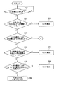
前述した構成のCDプレーヤ1は、機器本体5内にCD2,3,4を出し入れしていない状態では、ローラ20を停止している。CDプレーヤ1は、機器本体5内にCD2,3,4が挿入されると、まず、図7中のステップS1でCPU14が挿入検出器からの情報に基づいて、挿入口8内に前述したCD2,3,4などの物体が侵入したか否かを判定する。CPU14は、挿入口8内に前述したCD2,3,4などの物体が侵入していないと判定すると、ステップS1を繰り返し、挿入口8内に前述したCD2,3,4などの物体が侵入したと判定すると、モータ9を駆動して、ローラ20を前述したCD2,3,4が機器本体5内に侵入する方向に回転して、ステップS2に進む。こうして、ステップS1では、挿入口8内にCD2,3,4などが挿入されるまでローラ20を停止し、挿入口8内にCD2,3,4などが挿入されるとローラ20を回転する。   The CD player 1 configured as described above stops the roller 20 in a state where the CDs 2, 3, and 4 are not taken in and out of the apparatus main body 5. In the CD player 1, when CDs 2, 3, and 4 are inserted into the apparatus main body 5, first, in step S <b> 1 in FIG. 7, the CPU 14 inserts the CD 2 described above into the insertion slot 8 based on information from the insertion detector. , 3, 4, etc., are judged. If the CPU 14 determines that the object such as CD2, 3, 4 or the like has not entered the insertion slot 8, the CPU 14 repeats step S1 and the object such as CD2, 3, 4 or the like has entered the insertion slot 8. If it is determined that the motor 9 is driven, the roller 20 is rotated in the direction in which the above-described CDs 2, 3, and 4 enter the apparatus main body 5, and the process proceeds to step S2. Thus, in step S1, the roller 20 is stopped until the CDs 2, 3, 4 and the like are inserted into the insertion port 8, and the rollers 20 are rotated when the CDs 2, 3, 4 and the like are inserted into the insertion port 8.

ステップS2では、CPU14は、少なくとも一方の検出ピン10が機器本体5内に挿入されたCD2,3,4により押圧されて移動しているか否かを判定する。則ち、ステップS2では、図16に示すように、機器本体5内に挿入されたカード形CD4を図示方向の向きで真っ直ぐ入れたことにより一対の検出ピン10双方が移動していない状態であるか否かCD2,3,4などの物体がユーザにより引き抜かれたか否かの2つを判定する。ステップS2で、CPU14は、一対の検出ピン10双方が移動していないと判定すると、ステップS3に進み、少なくとも一方の検出ピン10が移動していると判定すると、ステップS4に進む。   In step S <b> 2, the CPU 14 determines whether or not at least one of the detection pins 10 is moved by being pressed by the CDs 2, 3 and 4 inserted into the device main body 5. That is, in step S2, as shown in FIG. 16, both the pair of detection pins 10 are not moved by inserting the card CD 4 inserted into the device main body 5 straight in the direction shown in the drawing. Whether or not an object such as CD2, 3, 4 is pulled out by the user is determined. In step S2, if the CPU 14 determines that both of the pair of detection pins 10 have not moved, the process proceeds to step S3. If the CPU 14 determines that at least one detection pin 10 has moved, the process proceeds to step S4.

ステップS4では、CPU14の外径判定部16が、変位センサ11からの検出ピン10の変位に基づいて、一対の検出ピン10双方が互いに離れた後、これら一対の検出ピン10双方が同時期に近づき始めたか否かを判定する。ステップS4では、CPU14の外径判定部16が、変位センサ11からの検出ピン10の変位に基づいて、一対の検出ピン10双方が同時期に近づき始めたか否かを判定することで、機器本体5内に挿入されたCD2,3,4の外縁が円弧状などの対称形であるか否かを判定する。   In step S <b> 4, after the outer diameter determination unit 16 of the CPU 14 moves away from the pair of detection pins 10 based on the displacement of the detection pin 10 from the displacement sensor 11, both of the pair of detection pins 10 are at the same time. It is determined whether or not it has started to approach. In step S <b> 4, the outer diameter determination unit 16 of the CPU 14 determines whether or not both of the pair of detection pins 10 have approached the same period based on the displacement of the detection pin 10 from the displacement sensor 11. 5 determines whether or not the outer edges of the CDs 2, 3, and 4 inserted in the disk 5 are symmetrical such as an arc.

ステップS4で、CPU14は、機器本体5内にCD2等の対称形であるものが挿入されたと判定すると、ステップS5に進み、一対の検出ピン10双方が同時期に近づき始めていないと判定すると、図8中のステップS10に進む。なお、このステップS4は、本明細書に記した対称判定ステップをなしており、挿入されたCD2,3,4の外縁に当接して離間方向に移動した検出ピン10が近づく方向に移動し始める時期からCD2,3,4が対称形であるか否かを判定する。   In step S4, if the CPU 14 determines that a symmetrical object such as CD2 is inserted in the device body 5, the process proceeds to step S5, and if it is determined that both of the pair of detection pins 10 have not started approaching at the same time, FIG. The process proceeds to step S10 in FIG. Note that this step S4 is the symmetry determination step described in this specification, and the detection pin 10 that has moved in the separation direction in contact with the outer edges of the inserted CDs 2, 3, and 4 starts to move in the approaching direction. It is determined from the time whether CDs 2, 3, and 4 are symmetrical.

ステップS5では、CPU14の外径判定部16は、変位センサ11からの検出ピン10の変位に基づいて、一対の検出ピン10双方が同時期に近づき始めた時の一対の検出ピン10間の間隔(最大距離)を算出する。そして、CPU14の外径判定部16は、算出した一対の検出ピン10間の間隔が前述したR,r又はこれらR,rと異なる値であるか否かを判定する。   In step S <b> 5, the outer diameter determination unit 16 of the CPU 14 determines the interval between the pair of detection pins 10 when both the pair of detection pins 10 begin to approach the same period based on the displacement of the detection pin 10 from the displacement sensor 11. (Maximum distance) is calculated. Then, the outer diameter determination unit 16 of the CPU 14 determines whether or not the calculated interval between the pair of detection pins 10 is R, r described above or a value different from these R, r.

CPU14の外径判定部16は、算出した一対の検出ピン10間の間隔が前述したR又はrと判定すると、ステップS7に進み、算出した一対の検出ピン10間の間隔が前述したR,rと異なる値であると判定すると、ステップS6に進む。こうして、ステップS5では、一対の検出ピン10間の最大距離から機器本体5内に挿入されたCD2,3,4の外径を判定する本明細書に記した外径判定ステップをなしている。   When the outer diameter determining unit 16 of the CPU 14 determines that the calculated distance between the pair of detection pins 10 is R or r described above, the process proceeds to step S7, and the calculated distance between the pair of detection pins 10 is R, r described above. If it is determined that the value is different from the above, the process proceeds to step S6. Thus, in step S5, the outer diameter determination step described in the present specification is performed to determine the outer diameter of the CDs 2, 3, and 4 inserted into the device main body 5 from the maximum distance between the pair of detection pins 10.

ステップS7では、CPU14の形状判定部18は、変位センサ11からの検出ピン10の変位に基づいて、一対の検出ピン10双方が近づく時の一対の検出ピン10間の変位の変化率を算出し、この算出した変化率が前述した予め定められた所定の範囲内であるか否かを判定する。CPU14の形状判定部18は、算出した変化率が前述した所定の範囲内であると判定すると、ステップS9に進み、算出した変化率が前述した所定の範囲内を越えると判定すると、ステップS8に進む。こうして、ステップS7では、機器本体5内に、円板状のCD2,3とカード形CD4のうちいずれかが挿入されているか否かを判定する本明細書に記した形状判定ステップをなしており、検出ピン10が近づく際の検出ピン10間の間隔の変化率からCD2,3,4の形状を判定する。   In step S <b> 7, the shape determination unit 18 of the CPU 14 calculates the change rate of the displacement between the pair of detection pins 10 when both the pair of detection pins 10 approach based on the displacement of the detection pin 10 from the displacement sensor 11. Then, it is determined whether or not the calculated change rate is within the predetermined range described above. If the shape determination unit 18 of the CPU 14 determines that the calculated change rate is within the predetermined range, the process proceeds to step S9. If the calculated change rate exceeds the predetermined range, the shape determination unit 18 proceeds to step S8. move on. Thus, in step S7, the shape determination step described in this specification for determining whether any one of the disk-shaped CDs 2 and 3 and the card type CD4 is inserted in the device main body 5 is performed. The shapes of the CDs 2, 3 and 4 are determined from the rate of change of the interval between the detection pins 10 when the detection pins 10 approach.

ステップS9では、CPU14は、機器本体5内に大径CD2と小径CD3とのうちいずれかが挿入されたと判定する。   In step S <b> 9, the CPU 14 determines that either the large diameter CD <b> 2 or the small diameter CD <b> 3 has been inserted into the device main body 5.

ステップS3,S6,S8では、CPU14は、機器本体5内にカード形CD4などの異形記録媒体が挿入されていると判定して、モータ9を逆転駆動して、ローラ20を機器本体5内に挿入されたカード形CD4を排出する方向に回転する。   In steps S3, S6, and S8, the CPU 14 determines that a deformed recording medium such as a card type CD4 is inserted in the device main body 5 and drives the motor 9 in the reverse direction to move the roller 20 into the device main body 5. It rotates in the direction of ejecting the inserted card type CD4.

前述したステップS1からステップS9までは、前述したように、機器本体5内に大径CD2が挿入されているか、機器本体5内に挿入された小径CD3が一対の検出ピン10双方を押圧したか、機器本体5内にカード形CD4が挿入されているかを判定する。   From step S1 to step S9 described above, as described above, is the large-diameter CD2 inserted in the device main body 5 or the small-diameter CD3 inserted in the device main body 5 pressed both the pair of detection pins 10? Then, it is determined whether or not the card-type CD 4 is inserted in the device body 5.

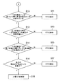
図8中のステップS10では、CPU14の第2ディスク判定部17は、一方の検出ピン10が他方の検出ピン10に近づいた際に、他方の検出ピン10が止まったままであるか否かを判定する。CPUの第2ディスク判定部17は、他方の検出ピン10が止まったままであると判定すると、ステップS12に進み、他方の検出ピン10が移動していると判定すると、ステップS11に進む。   In step S10 in FIG. 8, the second disk determination unit 17 of the CPU 14 determines whether or not the other detection pin 10 remains stopped when the one detection pin 10 approaches the other detection pin 10. To do. If the second disk determination unit 17 of the CPU determines that the other detection pin 10 remains stopped, the process proceeds to step S12. If the second detection pin 10 determines that the other detection pin 10 has moved, the process proceeds to step S11.

ステップS10では、他方の検出ピン10が止まったままであることは、小径CD3又はカード形CD4が一方の検出ピン10ののみに接触していることを示している。また、ステップS10では、他方の検出ピン10が移動していることは、カード形CD4が一対の検出ピン10双方に接触し、一方の検出ピン10が他方の検出ピン10に近づき始めても、他方の検出ピン10が一方の検出ピン10から離れる方向に移動していることなどを示している。   In step S10, the fact that the other detection pin 10 remains stopped indicates that the small-diameter CD3 or the card-shaped CD4 is in contact with only one detection pin 10. In step S10, the other detection pin 10 is moved because the card-shaped CD4 is in contact with both the pair of detection pins 10 and one detection pin 10 starts to approach the other detection pin 10. This indicates that the detection pin 10 is moving away from one detection pin 10.

ステップS12では、CPU14の第2ディスク判定部17は、変位センサ11からの情報に基づいて、一方の検出ピン10が他方の検出ピン10に近づき始めた時の一方の検出ピン10の変位が前述した所定の値A以上であるか否かを判定する。CPU14の第2ディスク判定部17は、一方の検出ピン10の変位が前述した所定の値A以上であると判定すると、ステップS14に進み、一方の検出ピン10の変位が前述した所定の値Aを下回ると判定すると、ステップS13に進む。一方の検出ピン10の変位が前述した所定の値A以上であることは、小径CD3が一方の検出ピン10のみに接触して該一方の検出ピン10のみを移動させていることと、カード形CD4が一方の検出ピン10のみに接触して一方の検出ピン10の変位が前述した所定の値A以上になっていることを示している。一方の検出ピン10の変位が前述した所定の値Aを下回ることは、カード形CD4が一方の検出ピン10のみに接触して、該一方の検出ピン10を移動させていることを示している。   In step S12, the second disk determination unit 17 of the CPU 14 determines the displacement of one detection pin 10 when one detection pin 10 starts to approach the other detection pin 10 based on information from the displacement sensor 11. It is determined whether the value is equal to or greater than the predetermined value A. When the second disk determination unit 17 of the CPU 14 determines that the displacement of one detection pin 10 is equal to or greater than the predetermined value A described above, the process proceeds to step S14, and the displacement of one detection pin 10 indicates the predetermined value A described above. If it is determined that the value is below, the process proceeds to step S13. The fact that the displacement of one detection pin 10 is not less than the predetermined value A described above means that the small-diameter CD3 is in contact with only one detection pin 10 and moves only the one detection pin 10, and the card shape. CD4 contacts only one detection pin 10 and the displacement of one detection pin 10 is equal to or greater than the predetermined value A described above. The fact that the displacement of one detection pin 10 falls below the predetermined value A described above indicates that the card-shaped CD 4 is in contact with only one detection pin 10 and moves the one detection pin 10. .

ステップS14では、CPU14の第2ディスク判定部17は、一方の検出ピン10が他方の検出ピン10に近づき始めた際に、ディスク検出器12からの情報に基づいて、該ディスク検出器12のLDからのレーザ光がPDに受光されているか否かを判定する。則ち、ステップS14では、ディスク検出器12のPDなどのダイオードが、小径CD3を検出したか否かを判定する。   In step S <b> 14, the second disk determination unit 17 of the CPU 14 determines the LD of the disk detector 12 based on the information from the disk detector 12 when one detection pin 10 starts to approach the other detection pin 10. It is determined whether or not the laser beam from is received by the PD. That is, in step S14, it is determined whether a diode such as a PD of the disk detector 12 has detected the small diameter CD3.

CPU14の第2ディスク判定部17は、ディスク検出器12のPDなどのダイオードが、小径CD3を検出した場合則ちディスク検出器12のLDからのレーザ光が遮られると、ステップS16に進み、小径CD3を検出しない場合則ちディスク検出器12のLDからのレーザ光が遮られないと、ステップS15に進む。   When the diode such as the PD of the disk detector 12 detects the small diameter CD3, that is, when the laser beam from the LD of the disk detector 12 is interrupted, the second disk determination unit 17 of the CPU 14 proceeds to step S16, and the small diameter When CD3 is not detected, that is, when the laser beam from the LD of the disk detector 12 is not blocked, the process proceeds to step S15.

CPU14の第2ディスク判定部17は、一方の検出ピン10のみがCD2,3により押圧されて移動し、この一方の検出ピン10が他方の検出ピン10に近づき始めた際に、ディスク検出器12のLDからのレーザ光が遮られることは、機器本体5内に小径CD3が挿入されたことを示し、ディスク検出器12のLDからのレーザ光がPDに受光されることは、機器本体5内にカード形CD4が挿入されたことを示している。   The second disc determination unit 17 of the CPU 14 moves when only one of the detection pins 10 is pressed by the CDs 2 and 3 and the one detection pin 10 starts to approach the other detection pin 10. The fact that the laser beam from the LD is blocked indicates that the small-diameter CD3 has been inserted into the device main body 5, and that the laser beam from the LD of the disk detector 12 is received by the PD is within the device main body 5. Indicates that a card type CD4 has been inserted.

ステップS16では、CPU14の第2ディスク判定部17は、変位センサ11からの情報により、他方の検出ピン10が止まったままであるか否かを判定する。CPU14の第2ディスク判定部17は、他方の検出ピン10が止まったままであると判定すると、ステップS18に進み、他方の検出ピン10が移動したと判定すると、ステップS17に進む。   In step S <b> 16, the second disk determination unit 17 of the CPU 14 determines whether or not the other detection pin 10 remains stopped based on information from the displacement sensor 11. If the second disk determination unit 17 of the CPU 14 determines that the other detection pin 10 remains stopped, the process proceeds to step S18. If the second detection pin 10 determines that the other detection pin 10 has moved, the process proceeds to step S17.

ステップS16で、他方の検出ピン10が移動することは、ディスク検出器12のLDからのレーザ光を遮ったカード形CD4などの異形記録媒体が、他方の検出ピン10に接触したことを示している。また、ステップS16で、他方の検出ピン10が止まったままであることは、小径CD3が一方の検出ピン10のみに接触して該一方の検出ピン10のみを移動することを示している。   The movement of the other detection pin 10 in step S16 indicates that a deformed recording medium such as a card-shaped CD4 that has blocked the laser beam from the LD of the disk detector 12 has contacted the other detection pin 10. Yes. In addition, the fact that the other detection pin 10 remains stopped in step S16 indicates that the small-diameter CD3 contacts only one detection pin 10 and moves only the one detection pin 10.

ステップS18では、CPU14の第2ディスク判定部17は、機器本体5内に小径CD3が挿入されたと判定する。ステップS11,S13,S15,S17では、CPU14は、機器本体5内にカード形CD4などの異形記録媒体が挿入されていると判定して、モータ9を逆転駆動して、ローラ20を機器本体5内に挿入されたカード形CD4を排出する方向に回転する。こうして、ステップS10からステップS18までは、前述したように、機器本体5内に挿入された小径CD3が一対の検出ピン10のうち一方の検出ピン10のみを押圧したか、機器本体5内にカード形CD4が挿入されているかを判定する。ステップS10からステップS18は、本明細書に記した第2ディスク判定ステップをなしている。ステップS10からステップS18では、ステップS4で機器本体5内に挿入されたCD2,3,4が非対称形であると判定すると、前記CD2,3,4を挿入する際に一対の検出ピン10が共に移動する場合は、前記CD2,3,4をカード形CD4などの異形記録媒体であると判定する。ステップS10からステップS18では、検出ピン10の一方が常に止まった状態で他方の検出ピン10の位置によりCD2,3,4の外径と形状を判別する。   In step S <b> 18, the second disk determination unit 17 of the CPU 14 determines that the small diameter CD 3 has been inserted into the device main body 5. In steps S11, S13, S15, and S17, the CPU 14 determines that an irregular recording medium such as a card type CD4 is inserted in the device main body 5 and drives the motor 9 in the reverse direction to move the roller 20 to the device main body 5. It rotates in the direction of ejecting the card-shaped CD4 inserted therein. Thus, from step S10 to step S18, as described above, the small-diameter CD3 inserted into the device main body 5 presses only one detection pin 10 of the pair of detection pins 10, or a card is inserted into the device main body 5. It is determined whether the CD4 is inserted. Steps S10 to S18 constitute the second disc determination step described in this specification. In steps S10 to S18, if it is determined that the CDs 2, 3, and 4 inserted into the device main body 5 in step S4 are asymmetrical, the pair of detection pins 10 are both inserted when the CDs 2, 3, and 4 are inserted. When moving, it is determined that the CDs 2, 3, and 4 are irregularly shaped recording media such as a card type CD4. In steps S10 to S18, the outer diameters and shapes of the CDs 2, 3, and 4 are determined based on the position of the other detection pin 10 in a state where one of the detection pins 10 is always stopped.

前述したように、判定手段としてのCPU14は、変位センサ11が検出した一対の検出ピン10の変位に基づいて、機器本体5内に挿入された記録媒体としてのCDが大径CD2と小径CD3とカード形CD4などの異形記録媒体とのうちいずれかであるかを判定する。そして、CPU14は、ステップS3,S6,S8,S11,S13,S15,S17のように、機器本体5内に挿入されたCDがカード形CD4などの異形記録媒体であると判定した際に、搬送ユニット6にカード形CD4などの異形記録媒体を機器本体5内から排出させる。   As described above, the CPU 14 serving as the determination unit determines that the CD as the recording medium inserted into the device main body 5 is the large diameter CD2 and the small diameter CD3 based on the displacement of the pair of detection pins 10 detected by the displacement sensor 11. It is determined whether it is one of a deformed recording medium such as a card type CD4. When the CPU 14 determines that the CD inserted into the device main body 5 is a deformed recording medium such as a card type CD4 as in steps S3, S6, S8, S11, S13, S15, and S17, the CPU 14 carries The unit 6 is caused to eject a deformed recording medium such as a card type CD 4 from the apparatus main body 5.

本実施例によれば、CPU14が、CD2,3,4と接触して移動する一対の検出ピン10の変位に基づいて、CD2,3,4を判別するので、確実に機器本体5内に挿入されたCD2,3,4がCD2,3か異形記録媒体としてのカード形CD4かを判別できる。   According to the present embodiment, the CPU 14 discriminates the CDs 2, 3, 4 based on the displacement of the pair of detection pins 10 that move in contact with the CDs 2, 3, 4. It is possible to determine whether the CDs 2, 3 and 4 are CDs 2 and 3 or a card-type CD 4 as an irregular recording medium.

また、CPU14は、異形記録媒体としてのカード形CD4であると判定すると、搬送ユニット6にこのカード形CD4を排出させる。このため、カード形CD4などの異形記録媒体が機器本体5内に収容される前に、このカード形CD4などの異形記録媒体を機器本体5外に排出できる。したがって、カード形CD4などの異形記録媒体が機器本体5内から排出できなくなることを防止できる。   On the other hand, when the CPU 14 determines that the card-shaped CD4 is the irregular-shaped recording medium, the CPU 14 causes the transport unit 6 to eject the card-shaped CD4. For this reason, before the deformed recording medium such as the card-shaped CD4 is accommodated in the apparatus main body 5, the deformed recording medium such as the card-shaped CD4 can be discharged out of the apparatus main body 5. Therefore, it is possible to prevent the irregular recording medium such as the card type CD4 from being discharged from the apparatus main body 5.

対称判定部15及びステップS4で、CD2,3,4が対称形であるか否かを判定する。このため、機器本体5内に挿入されたCD2,3,4が円弧状の対称形であるCD2,3かカード形CD4であるかを判別できる。   In the symmetry determination unit 15 and step S4, it is determined whether or not the CDs 2, 3, and 4 are symmetrical. For this reason, it is possible to determine whether the CDs 2, 3 and 4 inserted into the device main body 5 are the arc-shaped symmetrical CDs 2 and 3 or the card type CD4.

また、外径判定部16及びステップS5で、対称形であると判別されたCD2,3の外径R,rを判別する。このため、機器本体5内に収容されたCD2,3,4が、大径CD2又は小径CD3と同じ外径R,rのCDであるかを把握できる。   Further, the outer diameters R and r of the CDs 2 and 3 determined to be symmetrical in the outer diameter determination unit 16 and step S5 are determined. For this reason, it is possible to grasp whether the CDs 2, 3, and 4 accommodated in the device main body 5 are CDs having the same outer diameters R and r as the large diameter CD2 or the small diameter CD3.

さらに、第2ディスク判定部17及びステップS10からステップS18で、小径CD3であるかカード形CD4であるかを判別する。このため、機器本体5内に挿入されたCD2,3,4がディスク形記録媒体としての小径CD3か異形記録媒体としてのカード形CD4であるかを判別できる。   Further, in the second disc determination unit 17 and steps S10 to S18, it is determined whether it is a small-diameter CD3 or a card type CD4. For this reason, it is possible to determine whether the CDs 2, 3, and 4 inserted into the apparatus main body 5 are the small-diameter CD3 as the disk-shaped recording medium or the card-shaped CD4 as the irregular-shaped recording medium.

形状判定部18及びステップS7で、CDが円板状であるか否かを判定する。このため、機器本体5内に挿入されたCD2,3,4がディスク形記録媒体としてのCD2,3か異形記録媒体としてのカード形CD4であるかを判別できる。   In the shape determination unit 18 and step S7, it is determined whether or not the CD is disk-shaped. Therefore, it is possible to determine whether the CDs 2, 3 and 4 inserted into the apparatus main body 5 are the CDs 2 and 3 as the disk-type recording medium or the card-type CD 4 as the irregular-shaped recording medium.

前述した実施例では、異形記録媒体として、図4に示す平面形状が矩形状のカード形CD4を示している。しかしながら、本発明では、異形記録媒体として、図5に示す平面形状が樽形(小判形)のカード形CD4aを用いても良い。要するに、本発明では、円板状以外の形状の記録媒体を異形記録媒体とする。また、本発明では、検出ピン10の変位を検出できるセンサであれば、検出手段として種々のものを用いても良い。   In the embodiment described above, the card shape CD4 having a rectangular planar shape shown in FIG. 4 is shown as the irregular recording medium. However, in the present invention, a card-shaped CD 4a having a barrel shape (oval shape) as shown in FIG. 5 may be used as the irregular recording medium. In short, in the present invention, a recording medium having a shape other than a disk shape is used as a deformed recording medium. In the present invention, various detection means may be used as long as the sensor can detect the displacement of the detection pin 10.

さらに、本発明では、LDとPDとを備えた挿入検出器を設けずに、前述したステップS1では、変位センサ11からの情報に基づいて、前述した検出ピン10が移動したか否かで、挿入口10内にCD2,3,4などの物体が挿入されたか否かを判定しても良い。勿論、検出ピン10が移動すると、挿入口8内にCD2,3,4などの物体が挿入されたことを示し、検出ピン10が止まったままであると、挿入口8内にCD2,3,4などの物体が挿入されていないことを示す。   Furthermore, in the present invention, without providing an insertion detector provided with LD and PD, in the above-described step S1, whether or not the above-described detection pin 10 has moved based on the information from the displacement sensor 11, It may be determined whether or not an object such as CD2, 3, 4 or the like has been inserted into the insertion slot 10. Of course, movement of the detection pin 10 indicates that an object such as CD2, 3, 4 or the like has been inserted into the insertion slot 8, and if the detection pin 10 remains stopped, CD2, 3, 4 within the insertion slot 8 This indicates that no object has been inserted.

前述した実施例によれば、以下のCDプレーヤ1が得られる。   According to the embodiment described above, the following CD player 1 is obtained.

(付記1) 互いに外径の異なる大径CD2と小径CD3とを機器本体5に収容して、これらのCD2,3に記録された情報を読み出すCDプレーヤ1において、
互いに接離自在に設けられかつ互いに近づく方向に付勢されているとともに、前記大径CD2が機器本体5内に挿入される際に双方とも該CD2の外縁に接触して互いに離れる方向に移動し、前記小径CD3が機器本体5内に挿入される際に少なくとも一方が該小径CD3の外縁に接触して互いに離れる方向に移動する一対の検出ピン10と、
前記検出ピン10の前記接離方向に沿った変位を検出する変位センサ11と、
前記機器本体5内にCD2,3,4,4aを導く搬送ユニット6と、
前記変位センサ11が検出した前記一対の検出ピン10の変位に基づいて、機器本体5内に挿入されたCD2,3,4,4aが前記大径CD2と前記小径CD3とこれらのCD2,3と外形の異なるカード形CD4,4aとのうち何れか一つであるかを判定し、機器本体5内に挿入されたCD2,3,4,4aが前記カード形CD4,4aであると判定した際に前記搬送ユニット6に前記CD2,3,4,4aを前記機器本体5内から排出させるCPU14と、
を備えたことを特徴とするCDプレーヤ1。
(Additional remark 1) In the CD player 1 which accommodates the large-diameter CD2 and the small-diameter CD3 having different outer diameters in the apparatus main body 5 and reads information recorded on these CDs 2 and 3,
The large-diameter CD2 is provided so as to be able to come in contact with and away from each other, and is urged in a direction approaching each other, and when the large-diameter CD2 is inserted into the apparatus main body 5, both contact with the outer edge of the CD2 A pair of detection pins 10 at least one of which contacts the outer edge of the small diameter CD3 and moves away from each other when the small diameter CD3 is inserted into the device main body 5;
A displacement sensor 11 for detecting a displacement of the detection pin 10 along the contact / separation direction;
A transport unit 6 for guiding CDs 2, 3, 4 and 4a into the device body 5;
Based on the displacement of the pair of detection pins 10 detected by the displacement sensor 11, the CDs 2, 3, 4, 4 a inserted into the device body 5 are the large diameter CD 2, the small diameter CD 3, and the CDs 2, 3. When it is determined whether it is one of the card types CD4, 4a having different outer shapes, and it is determined that the CD2, 3, 4, 4a inserted into the device body 5 is the card type CD4, 4a A CPU 14 for causing the transport unit 6 to eject the CDs 2, 3, 4 and 4a from the device main body 5;
A CD player 1 comprising:

(付記2) 前記CPU14は、前記一対の検出ピン10間の最大距離からCD2,3,4,4aの外径を判定する外径判定部16と、前記挿入されたCD2,3,4,4aの外縁に当接して離間方向に移動した前記検出ピン10が近づく際の変化率からCD2,3,4,4aの形状を判定する形状判定部18と、
を備えたことを特徴とする付記1記載のCDプレーヤ1。
(Supplementary Note 2) The CPU 14 includes an outer diameter determination unit 16 that determines the outer diameter of the CDs 2, 3, 4, and 4a from the maximum distance between the pair of detection pins 10, and the inserted CDs 2, 3, 4, and 4a. A shape determination unit 18 that determines the shape of the CDs 2, 3, 4, and 4a from the rate of change when the detection pin 10 that is in contact with the outer edge and moved in the separation direction approaches,
A CD player 1 according to appendix 1, characterized by comprising:

(付記3) 前記CPU14は、CD2,3,4,4aの外縁に当接して離間方向に移動した前記検出ピン10が近づく方向に移動し始める時期からCD2,3,4,4aが対称形であるか否かを判定する対称判定部15を更に含み、
前記対称判定部15でCD2,3,4,4aを対称形であると判定すると、前記外径判定部16と前記形状判定部18で外径と形状を判定し、
前記対称判定部15でCD2,3,4,4aが非対称形であると判定すると、前記一対の検出ピン10が共に移動する場合は、CD2,3,4,4aを異形記録媒体であると判定すると共に、前記検出ピン10の一方が常に止まった状態で他方の検出ピン10の位置によりCD2,3,4,4aの外径と形状を判別する第2ディスク判定部17と、
を備えたことを特徴とする付記2記載のCDプレーヤ1。
(Supplementary Note 3) In the CPU 14, CDs 2, 3, 4, and 4 a are symmetrical from the time when the detection pin 10 that has contacted the outer edges of the CDs 2, 3, 4, 4 a and moved in the separating direction starts to move in the approaching direction. A symmetry determining unit 15 for determining whether or not there is,
If the symmetry determining unit 15 determines that CDs 2, 3, 4, and 4a are symmetrical, the outer diameter determining unit 16 and the shape determining unit 18 determine the outer diameter and shape,
When the symmetry determining unit 15 determines that the CDs 2, 3, 4, and 4a are asymmetric, when the pair of detection pins 10 move together, the CDs 2, 3, 4, and 4a are determined to be irregularly shaped recording media. And a second disk determination unit 17 for determining the outer diameter and shape of the CDs 2, 3, 4 and 4a according to the position of the other detection pin 10 with one of the detection pins 10 always stopped.
The CD player 1 according to appendix 2, characterized by comprising:

(付記4) 互いに外径の異なる大径CD2と小径CD3とを機器本体5に収容して、これらのCD2,3に記録された情報を読み出すCDプレーヤ1のCDの判別方法において、
前記CDプレーヤ1が、互いに接離自在に設けられかつ互いに近づく方向に付勢されているとともに、前記CD2が機器本体5内に挿入される際に双方とも該CD2の外縁に接触して互いに離れる方向に移動し、前記CD3が機器本体5内に挿入される際に少なくとも一方がCD3の外縁に接触して互いに離れる方向に移動する一対の検出ピン10と、
前記検出ピン10の前記接離方向に沿った変位を検出する変位センサ11と、を備え、
前記変位センサ11が検出した前記一対の検出ピン10間の最大距離からCD2,3,4,4aの外径を判定する外径判定ステップS5と、
CD2,3,4,4aの外縁に当接して離間方向に移動した前記検出ピン10が近づく際の変化率からCD2,3,4,4aの形状を判定する形状判定ステップS7と、
を含んだことを特徴とするCDプレーヤ1のCDの判別方法。
(Additional remark 4) In the CD discriminating method of the CD player 1 in which the large-diameter CD2 and the small-diameter CD3 having different outer diameters are accommodated in the apparatus main body 5 and information recorded on these CD2 and CD3 is read.
The CD players 1 are provided so as to be able to come into contact with each other and are urged in a direction approaching each other. When the CD 2 is inserted into the apparatus main body 5, both come into contact with the outer edge of the CD 2 and are separated from each other. A pair of detection pins 10 that move in a direction away from each other when at least one of them contacts the outer edge of the CD 3 when the CD 3 is inserted into the device body 5;
A displacement sensor 11 for detecting a displacement of the detection pin 10 along the contact / separation direction,
An outer diameter determination step S5 for determining the outer diameter of the CDs 2, 3, 4 and 4a from the maximum distance between the pair of detection pins 10 detected by the displacement sensor 11;
Shape determination step S7 for determining the shape of CD2,3,4,4a from the rate of change when the detection pin 10 that has contacted the outer edge of CD2,3,4,4a and moved in the separation direction approaches,
A method for discriminating a CD of a CD player 1 characterized by including:

(付記5) CD2,3,4,4aの外縁に当接して離間方向に移動した前記検出ピン10が近づく方向に移動し始める時期からCD2,3,4,4aを対称形であるか否かを判定する対称判定ステップS4を更に含み、
前記対称判定ステップS4で機器本体5内に挿入されたCD2,3,4,4aが対称形であると判定すると、前記外径判定ステップS5と前記形状判定ステップS7で外径と形状を判定し、
前記対称判定ステップS4で機器本体5内に挿入されたCD2,3,4,4aが非対称形であると判定すると、前記一対の検出ピン10が共に移動する場合は、CD2,3,4,4aを異形記録媒体であると判定すると共に、前記検出ピン10の一方が常に止まった状態で他方の検出ピン10の位置によりCD2,3,4,4aの外径と形状を判別する第2ディスク判定ステップS10〜S18を含んだことを特徴とする付記4記載のCDプレーヤ1のCDの判別方法。
(Supplementary Note 5) Whether CDs 2, 3, 4, and 4a are symmetrical from the time when the detection pins 10 that have contacted the outer edges of CDs 2, 3, 4, and 4a and moved in the separating direction start moving in the approaching direction A symmetry determination step S4 for determining
If it is determined in the symmetry determination step S4 that the CDs 2, 3, 4 and 4a inserted into the device main body 5 are symmetrical, the outer diameter and shape are determined in the outer diameter determination step S5 and the shape determination step S7. ,
If it is determined in the symmetry determination step S4 that the CDs 2, 3, 4 and 4a inserted into the device main body 5 are asymmetric, if the pair of detection pins 10 move together, Is determined to be an irregular recording medium, and the outer diameter and shape of the CDs 2, 3, 4 and 4a are discriminated based on the position of the other detection pin 10 with one of the detection pins 10 always stopped. The method for discriminating a CD of the CD player 1 according to supplementary note 4, including steps S10 to S18.

なお、前述した実施例は本発明の代表的な形態を示したに過ぎず、本発明は、実施例に限定されるものではない。即ち、本発明の骨子を逸脱しない範囲で種々変形して実施することができる。   In addition, the Example mentioned above only showed the typical form of this invention, and this invention is not limited to an Example. That is, various modifications can be made without departing from the scope of the present invention.

本発明の一実施例にかかる記録媒体再生装置としてのCDプレーヤの外観を示す斜視図である。1 is a perspective view showing an appearance of a CD player as a recording medium playback apparatus according to an embodiment of the present invention. 図1に示されたCDプレーヤで情報が読み出される大径ディスク形記録媒体としての大径CDを示す平面図である。FIG. 2 is a plan view showing a large-diameter CD as a large-diameter disk-type recording medium from which information is read out by the CD player shown in FIG. 1. 図1に示されたCDプレーヤで情報が読み出される小径ディスク形記録媒体としての小径CDを示す平面図である。FIG. 2 is a plan view showing a small-diameter CD as a small-diameter disk-type recording medium from which information is read out by the CD player shown in FIG. 1. 図1に示されたCDプレーヤの機器本体内に挿入されることを防止する異形記録媒体としてのカード形CDを示す平面図である。FIG. 2 is a plan view showing a card-type CD as a deformed recording medium for preventing insertion into the device main body of the CD player shown in FIG. 1. 図4に示されたカード形CDの変形例を示す平面図である。It is a top view which shows the modification of card form CD shown by FIG. 図1に示されたCDプレーヤの主要な構成を示す説明図である。It is explanatory drawing which shows the main structures of CD player shown by FIG. 図6に示されたCDプレーヤがCDを判別する過程を示すフローチャートの一部である。7 is a part of a flowchart showing a process of discriminating a CD by the CD player shown in FIG. 図7に示されたフローチャートの残りの部分である。It is the remaining part of the flowchart shown in FIG. 図6に示されたCDプレーヤ内に大径ディスク形記録媒体としての大径CDが挿入される状態を示す説明図である。FIG. 7 is an explanatory diagram showing a state in which a large-diameter CD as a large-diameter disk type recording medium is inserted into the CD player shown in FIG. 6. 図9に示された状態からさらに大径ディスク形記録媒体としての大径CDが奥に挿入された状態を示す説明図である。FIG. 10 is an explanatory diagram showing a state in which a large-diameter CD as a large-diameter disk type recording medium is further inserted from the state shown in FIG. 9. 図10に示された状態からさらに大径ディスク形記録媒体としての大径CDが奥に挿入された状態を示す説明図である。FIG. 11 is an explanatory diagram showing a state in which a large-diameter CD as a large-diameter disk type recording medium is further inserted from the state shown in FIG. 10. 図6に示されたCDプレーヤ内に小径ディスク形記録媒体としての小径CDが挿入される状態を示す説明図である。FIG. 7 is an explanatory diagram showing a state in which a small-diameter CD as a small-diameter disk-type recording medium is inserted into the CD player shown in FIG. 6. 図12に示された状態からさらに小径ディスク形記録媒体としての小径CDが奥に挿入された状態を示す説明図である。FIG. 13 is an explanatory view showing a state where a small-diameter CD as a small-diameter disk-type recording medium is further inserted from the state shown in FIG. 12. 図13に示された状態からさらに小径ディスク形記録媒体としての小径CDが奥に挿入された状態を示す説明図である。FIG. 14 is an explanatory view showing a state where a small-diameter CD as a small-diameter disk-type recording medium is further inserted from the state shown in FIG. 13. 図12に示された小径ディスク形記録媒体としての小径CDが挿入される状態の他の例を示す説明図である。FIG. 13 is an explanatory diagram showing another example of a state in which a small-diameter CD as the small-diameter disk-type recording medium shown in FIG. 12 is inserted. 図4に示されたカード形CDが挿入される状態を示す説明図である。It is explanatory drawing which shows the state in which the card-type CD shown by FIG. 4 is inserted. 図16に示されたカード形CDが挿入される状態の他の例を示す説明図である。It is explanatory drawing which shows the other example of the state by which the card form CD shown by FIG. 16 is inserted. 図17に示されたカード形CDが挿入される状態の更に他の例を示す説明図である。It is explanatory drawing which shows the further another example of the state by which the card form CD shown by FIG. 17 is inserted. 図18に示されたカード形CDが挿入される状態の別の他の例を示す説明図である。It is explanatory drawing which shows another example of the state by which the card form CD shown by FIG. 18 is inserted. 図19に示されたカード形CDが挿入される状態の更に別の他の例を示す説明図である。It is explanatory drawing which shows another example of the state by which the card-type CD shown by FIG. 19 is inserted.

符号の説明Explanation of symbols

1 CDプレーヤ(記録媒体再生装置)
2 大径CD(大径ディスク形記録媒体、記録媒体)
3 小径CD(小径ディスク形記録媒体、記録媒体)
4,4a カード形CD(異形記録媒体、記録媒体)
5 機器本体
6 搬送ユニット(搬送手段)
10 検出ピン
11 変位センサ(検出手段)
14 CPU(判定手段)
15 対称判定部
16 外径判定部
17 第2ディスク判定部
18 形状判定部
21 第1ディスク判定部
S4 対称判定ステップ
S5 外径判定ステップ
S10〜S18 第2ディスク判定ステップ
S7 形状判定ステップ
A 所定の値
1 CD player (recording medium playback device)
2 Large-diameter CD (large-diameter disk-type recording medium, recording medium)
3 Small-diameter CD (small-diameter disk-type recording medium, recording medium)
4,4a Card type CD (Atypical recording medium, recording medium)
5 Equipment body 6 Transport unit (transport means)
10 detection pin 11 displacement sensor (detection means)
14 CPU (determination means)
DESCRIPTION OF SYMBOLS 15 Symmetry determination part 16 Outer diameter determination part 17 2nd disk determination part 18 Shape determination part 21 1st disk determination part S4 Symmetry determination step S5 Outer diameter determination step S10-S18 2nd disk determination step S7 Shape determination step A Predetermined value

Claims (8)

互いに外径の異なる大径ディスク形記録媒体と小径ディスク形記録媒体とを機器本体に収容して、これらのディスク形記録媒体に記録された情報を読み出す記録媒体再生装置において、
互いに接離自在に設けられかつ互いに近づく方向に付勢されているとともに、前記大径ディスク形記録媒体が機器本体内に挿入される際に双方とも該大径ディスク形記録媒体の外縁に接触して互いに離れる方向に移動し、前記小径ディスク形記録媒体が機器本体内に挿入される際に少なくとも一方が該小径ディスク形記録媒体の外縁に接触して互いに離れる方向に移動する一対の検出ピンと、
前記検出ピンの前記接離方向に沿った変位を検出する検出手段と、
前記機器本体内に記録媒体を導く搬送手段と、
前記検出手段が検出した前記一対の検出ピンの変位に基づいて、機器本体内に挿入された記録媒体が前記大径ディスク形記録媒体と前記小径ディスク形記録媒体とこれらのディスク形記録媒体とは外形の異なる異形記録媒体とのうち何れか一つであるかを判定し、機器本体内に挿入された記録媒体が前記異形記録媒体であると判定した際に前記搬送手段に前記記録媒体を前記機器本体内から排出させる判定手段と、
を備えたことを特徴とする記録媒体再生装置。
In a recording medium reproducing apparatus for storing a large-diameter disk-shaped recording medium and a small-diameter disk-shaped recording medium having different outer diameters in an apparatus body and reading information recorded on these disk-shaped recording media,
They are provided so as to be able to come in contact with each other and are urged toward each other, and when the large-diameter disk-type recording medium is inserted into the main body of the apparatus, both come into contact with the outer edge of the large-diameter disk-type recording medium. A pair of detection pins that move in a direction away from each other and at least one of them contacts the outer edge of the small-diameter disk-shaped recording medium when the small-diameter disk-shaped recording medium is inserted into the apparatus body, and
Detecting means for detecting displacement along the contact / separation direction of the detection pin;
Conveying means for guiding a recording medium into the device body;
Based on the displacement of the pair of detection pins detected by the detection means, the recording medium inserted into the apparatus main body is the large-diameter disk-shaped recording medium, the small-diameter disk-shaped recording medium, and these disk-shaped recording media. It is determined whether it is any one of the irregular shaped recording media having different outer shapes, and when it is determined that the recording medium inserted in the apparatus main body is the irregular shaped recording medium, the recording medium is transferred to the conveying means. Determination means for discharging from inside the device body;
A recording medium reproducing apparatus comprising:
前記判定手段は、前記記録媒体の外径を判定する外径判定部と前記記録媒体の形状を判別する形状判定部とを有する第1ディスク判定部を備えたことを特徴とする請求項1記載の記録媒体再生装置。   2. The disc determination unit according to claim 1, wherein the determination unit includes a first disc determination unit having an outer diameter determination unit that determines the outer diameter of the recording medium and a shape determination unit that determines the shape of the recording medium. Recording medium playback device. 前記第1ディスク判定部の外径判定部は、前記一対の検出ピン間の最大距離から前記記録媒体の外径を判定し、
前記形状判定部は、前記挿入された記録媒体の外縁に当接して離間方向に移動した前記検出ピンが近づく際の変化率から前記記録媒体の形状を判定することを特徴とする請求項2記載の記録媒体再生装置。
The outer diameter determination unit of the first disc determination unit determines the outer diameter of the recording medium from the maximum distance between the pair of detection pins,
3. The shape determination unit according to claim 2, wherein the shape determination unit determines the shape of the recording medium from a rate of change when the detection pin that has moved in the separation direction comes into contact with an outer edge of the inserted recording medium. Recording medium playback device.
前記判定手段は、前記機器本体内に挿入された記録媒体が対称形であるか否かを判定する対称判定部を更に備えたことを特徴とする請求項2又は請求項3に記載の記録媒体再生装置。   The recording medium according to claim 2, wherein the determination unit further includes a symmetry determination unit that determines whether or not the recording medium inserted into the device main body is symmetrical. Playback device. 前記判定手段の対称判定部は、前記挿入された記録媒体の外縁に当接して離間方向に移動した前記検出ピンが近づく方向に移動し始める時期から前記記録媒体が対称形であるか否かを判別することを特徴とする請求項4記載の記録媒体再生装置。   The symmetry determining unit of the determining means determines whether or not the recording medium is symmetrical from the time when the detection pin that has contacted the outer edge of the inserted recording medium and moved in the separating direction starts moving in the approaching direction. The recording medium reproducing apparatus according to claim 4, wherein the recording medium reproducing apparatus is discriminated. 前記判定手段は、前記機器本体に挿入された記録媒体が対称形である場合に前記第1ディスク判定部が記録媒体の外径と形状と判定し、前記機器本体に挿入された記録媒体が非対称形である場合に前記記録媒体を挿入する際に前記一対の検出ピンが共に移動する場合は、前記記録媒体を異形記録媒体であると判定すると共に、前記検出ピンの一方が常に止まった状態である場合は、前記他方の検出ピンの位置により前記記録媒体の外径と形状を判別する第2ディスク判定部を備えたことを特徴とする請求項5記載の記録媒体再生装置。   The determination means determines that the first disk determination unit determines the outer diameter and shape of the recording medium when the recording medium inserted into the device main body is symmetrical, and the recording medium inserted into the device main body is asymmetric. If the pair of detection pins move together when the recording medium is inserted when the recording medium is inserted, it is determined that the recording medium is an irregular recording medium, and one of the detection pins is always stopped. 6. The recording medium reproducing apparatus according to claim 5, further comprising a second disc determination unit that determines an outer diameter and a shape of the recording medium based on a position of the other detection pin. 互いに外径の異なる大径ディスク形記録媒体と小径ディスク形記録媒体とを機器本体に収容して、これらのディスク形記録媒体に記録された情報を読み出す記録媒体再生装置の記録媒体の判別方法において、
前記記録媒体再生装置が、互いに接離自在に設けられかつ互いに近づく方向に付勢されているとともに、前記大径ディスク形記録媒体が機器本体内に挿入される際に双方とも該大径ディスク形記録媒体の外縁に接触して互いに離れる方向に移動し、前記小径ディスク形記録媒体が機器本体内に挿入される際に少なくとも一方が該小径ディスク形記録媒体の外縁に接触して互いに離れる方向に移動する一対の検出ピンと、
前記検出ピンの前記接離方向に沿った変位を検出する検出手段と、を備え、
前記検出手段が検出した前記一対の検出ピン間の最大距離から前記記録媒体の外径を判定する外径判定ステップと、
前記挿入された記録媒体の外縁に当接して離間方向に移動した前記検出ピンが近づく際の変化率から前記記録媒体の形状を判定する形状判定ステップと、
を含んだことを特徴とする記録媒体再生装置の記録媒体の判別方法。
In a method for discriminating a recording medium of a recording medium reproducing apparatus in which a large-diameter disk-type recording medium and a small-diameter disk-type recording medium having different outer diameters are housed in an apparatus body and information recorded on these disk-type recording media is read ,
The recording medium playback devices are provided so as to be able to come in contact with each other and are urged toward each other, and when the large-diameter disk-type recording medium is inserted into the apparatus main body, When the small-diameter disk-shaped recording medium is inserted into the apparatus main body, the at least one of the small-diameter disk-shaped recording medium contacts the outer edge of the small-diameter disk-shaped recording medium and moves away from each other. A pair of moving detection pins;
Detecting means for detecting a displacement along the contact / separation direction of the detection pin,
An outer diameter determination step of determining an outer diameter of the recording medium from a maximum distance between the pair of detection pins detected by the detection means;
A shape determination step of determining the shape of the recording medium from the rate of change when the detection pin that has moved in the separation direction comes into contact with the outer edge of the inserted recording medium;
A method for discriminating a recording medium of a recording medium reproducing apparatus, comprising:
前記挿入された記録媒体の外縁に当接して離間方向に移動した前記検出ピンが近づく方向に移動し始める時期から前記記録媒体を対称形であるか否かを判定する対称判定ステップを更に含み、前記対称判定ステップで前記機器本体内に挿入された記録媒体が対称形であると判定すると、前記外径判定ステップと前記形状判定ステップで外径と形状を判定し、
前記対称判定ステップで前記機器本体内に挿入された記録媒体が非対称形であると判定すると、前記記録媒体を挿入する際に前記一対の検出ピンが共に移動する場合は、前記記録媒体を異形記録媒体であると判定すると共に、前記検出ピンの一方が常に止まった状態で他方の検出ピンの位置により前記記録媒体の外径と形状を判別する第2ディスク判定ステップを更に含んだことを特徴とする請求項7記載の記録媒体再生装置の記録媒体の判別方法。
A symmetry determining step of determining whether or not the recording medium is symmetrical from the time when the detection pin that has moved in the separating direction in contact with the outer edge of the inserted recording medium starts to move in the approaching direction; When it is determined that the recording medium inserted into the device main body is symmetrical in the symmetry determination step, the outer diameter and shape are determined in the outer diameter determination step and the shape determination step,
If it is determined in the symmetry determination step that the recording medium inserted into the device main body is asymmetric, the pair of detection pins move together when the recording medium is inserted. And a second disc determination step of determining the outer diameter and shape of the recording medium according to the position of the other detection pin in a state where one of the detection pins is always stopped. A method for discriminating a recording medium of a recording medium reproducing apparatus according to claim 7.
JP2004104743A 2004-03-31 2004-03-31 Recording medium playback device and discriminating method of recording medium of the same Pending JP2005293681A (en)

Priority Applications (2)

Application Number Priority Date Filing Date Title
JP2004104743A JP2005293681A (en) 2004-03-31 2004-03-31 Recording medium playback device and discriminating method of recording medium of the same
US11/094,588 US20050219965A1 (en) 2004-03-31 2005-03-31 Record medium reproduction unit and method for recognizing record medium of reproduction unit

Applications Claiming Priority (1)

Application Number Priority Date Filing Date Title
JP2004104743A JP2005293681A (en) 2004-03-31 2004-03-31 Recording medium playback device and discriminating method of recording medium of the same

Publications (1)

Publication Number Publication Date
JP2005293681A true JP2005293681A (en) 2005-10-20

Family

ID=35054132

Family Applications (1)

Application Number Title Priority Date Filing Date
JP2004104743A Pending JP2005293681A (en) 2004-03-31 2004-03-31 Recording medium playback device and discriminating method of recording medium of the same

Country Status (2)

Country Link
US (1) US20050219965A1 (en)
JP (1) JP2005293681A (en)

Families Citing this family (3)

* Cited by examiner, † Cited by third party
Publication number Priority date Publication date Assignee Title
EP1012839A4 (en) * 1997-04-30 2001-01-10 Spectra Logic Corp Data cartridge library system
US6639751B2 (en) * 2001-10-19 2003-10-28 Spectra Logic Corporation Data cartridge library
JPWO2006030729A1 (en) * 2004-09-13 2008-05-15 松下電器産業株式会社 Disk unit

Family Cites Families (3)

* Cited by examiner, † Cited by third party
Publication number Priority date Publication date Assignee Title
US6288982B1 (en) * 1997-03-03 2001-09-11 Alpine Electronics, Inc. Disk apparatus and method of locating/discriminating disks using the same
JP3754834B2 (en) * 1998-11-09 2006-03-15 パイオニア株式会社 Recording / playback device
TW556158B (en) * 2001-11-23 2003-10-01 Lite On It Corp Method for determining the radius of compact disk and the compact disk data access device

Also Published As

Publication number Publication date
US20050219965A1 (en) 2005-10-06

Similar Documents

Publication Publication Date Title
US6288982B1 (en) Disk apparatus and method of locating/discriminating disks using the same
CN1320263A (en) disk loading device
JP2005293681A (en) Recording medium playback device and discriminating method of recording medium of the same
EP1089272B1 (en) Apparatus and method for detecting abnormal insertion of disc body
JP4082695B2 (en) RECORDING MEDIUM REPRODUCING DEVICE AND RECORDING MEDIUM REPRODUCING METHOD FOR RECORDING MEDIUM
JP3696076B2 (en) Slot-in type optical disk playback device
US20070288946A1 (en) Method and apparatus for discriminating discs
JP4275079B2 (en) Optical disk device
JP4522401B2 (en) Disk unit
JP2011018389A (en) Disk apparatus
JP2006012252A (en) Disk device, and method for preventing simultaneous insertion of two disks therein
JP3568190B2 (en) Slot-in type optical disc playback device
JP2003208744A (en) Disk drive, and method and program for controlling carrying of disk drive
JP2627145B2 (en) Disc player
KR100590227B1 (en) Optical disc recognition device of multi changer and its method
US20050185527A1 (en) Apparatus and method for controlling an optical disc drive to feed and eject a disc
JP2004241048A (en) Optical disk recording/reproducing device
KR100635678B1 (en) Slot-in type optical disc player
JP3909211B2 (en) Disk unit
JP5027931B2 (en) Information processing device
JP4759084B2 (en) Information processing device
US20050190661A1 (en) Counting device used in optical recording/reproducing apparatus
JP2005293656A (en) Disc player
JP2010040058A (en) Information processing device
JP2004288233A (en) Recording medium reproducing/recording device

Legal Events

Date Code Title Description
A621 Written request for application examination

Free format text: JAPANESE INTERMEDIATE CODE: A621

Effective date: 20070219

A977 Report on retrieval

Free format text: JAPANESE INTERMEDIATE CODE: A971007

Effective date: 20071211

A131 Notification of reasons for refusal

Free format text: JAPANESE INTERMEDIATE CODE: A131

Effective date: 20071225

A02 Decision of refusal

Free format text: JAPANESE INTERMEDIATE CODE: A02

Effective date: 20080422