JP2005293694A - Optical pickup device and optical disk device - Google Patents
Optical pickup device and optical disk device Download PDFInfo
- Publication number
- JP2005293694A JP2005293694A JP2004105689A JP2004105689A JP2005293694A JP 2005293694 A JP2005293694 A JP 2005293694A JP 2004105689 A JP2004105689 A JP 2004105689A JP 2004105689 A JP2004105689 A JP 2004105689A JP 2005293694 A JP2005293694 A JP 2005293694A
- Authority
- JP
- Japan
- Prior art keywords
- lens
- optical disk
- optical
- pickup
- optical disc
- Prior art date
- Legal status (The legal status is an assumption and is not a legal conclusion. Google has not performed a legal analysis and makes no representation as to the accuracy of the status listed.)
- Pending
Links
Images

Landscapes
- Moving Of The Head For Recording And Reproducing By Optical Means (AREA)
- Optical Head (AREA)
Abstract
【課題】 簡単な構成により不用意にレンズへの接触を回避させてレンズの汚染による不具合を解消することができる構成を備えた光ピックアップ装置を提供する。
【解決手段】 光ディスクに対面するレンズを備え、該レンズが上記光ディスクの内周方向および外周方向に移動されることで走査可能な構成を備えた光ピックアップ装置において、上記光ディスクを回転駆動するスピンドルモータに上記光ディスクを固定するクランプ3を支持するためのクランプホルダー2の占有領域内と該占有領域から上記光ディスクに対する走査領域へと移動させるための移動手段104とを備え、上記移動手段104は、上記光ディスクを外部に引き出す際または光ディスクに対する書き込みあるいは再生終了時のいずれかの時期に上記レンズを上記クランプホルダー2の占有領域内に位置させることを特徴としている。
【選択図】 図7
PROBLEM TO BE SOLVED: To provide an optical pickup device having a configuration capable of avoiding inadvertent contact with a lens with a simple configuration and solving a problem due to contamination of the lens.
A spindle motor that includes a lens facing an optical disk and that is configured to be scanned by moving the lens in an inner circumferential direction and an outer circumferential direction of the optical disk. The spindle motor rotates and drives the optical disk. And a moving means 104 for moving the occupied area of the clamp holder 2 for supporting the clamp 3 for fixing the optical disk to the scanning area for the optical disk from the occupied area. The lens is positioned within the occupied area of the clamp holder 2 when the optical disk is pulled out or at any time when writing or reproduction on the optical disk is completed.
[Selection] Figure 7
Description
本発明は、光ピックアップ装置および光ディスク装置に関し、さらに詳しくは、ピックアップ装置に用いられるレンズの保護機構に関する。 The present invention relates to an optical pickup device and an optical disk device, and more particularly to a protection mechanism for a lens used in the pickup device.
大容量の情報を記録する媒体の一つに光ディスクがあり、光ディスクには、1回だけの書き込みが可能なCD−R(CDレコーダブル)、複数回の書き込み消去を繰り返し可能なCD−E(CDイレーザブル)あるいはCD−RW(CDリライタブル)がある。また、CDとは別にこれよりもさらに大容量の情報記録が可能なDVD(デジタルバーサライトディスク)もある。 An optical disk is one of the media for recording large-capacity information. The optical disk is a CD-R (CD recordable) that can be written only once, and a CD-E (CD-E that can be repeatedly written and erased multiple times). CD erasable) or CD-RW (CD rewritable). In addition to the CD, there is a DVD (Digital Versalite Disc) capable of recording information of a larger capacity than this.
これら各光ディスクの読み書きを行う光ディスク装置には、光ピックアップおよびこれに関連する部材を収納している光ディスク装置本体から光ディスクを搭載した状態で保持可能なトレイ部のみが外部に取り出される方式と、光ピックアップおよびこれに関連する部材が収納されている光ディスク装置本体毎、外部に取り出される方式とがある。 The optical disk apparatus that reads and writes each of these optical disks includes a system in which only a tray portion that can hold an optical disk in a state where the optical disk is mounted is taken out from an optical disk apparatus main body that houses an optical pickup and related members, There is a system in which an optical disk apparatus main body in which a pickup and related members are stored is taken out to the outside.
上述した各方式を用いる光ディスク装置には、概ね、次の構成部材が装備されている。
光ピックアップ、光ピックアップのアクチュエータ、アクチュエータを支持しかつ、光源である半導体レーザー等の光学部品が組み込まれているピックアップハウジング部、ピックアップハウジングをシークモータなどにより光ディスクの内周あるいは外周に向けて移動させるシークモータ等の駆動源およびピックアップハウジングを光ディスクの内周あるいは外周に向けてガイドするガイドレールなどを有した光ピックアップの移送手段、光ディスクの回転駆動を行うスピンドルモータ等である(例えば、特許文献1)。
The optical disk apparatus using each of the above-described methods is generally equipped with the following components.
An optical pickup, an optical pickup actuator, a pickup housing portion that supports the actuator and incorporates an optical component such as a semiconductor laser as a light source, and the pickup housing is moved toward the inner or outer periphery of the optical disk by a seek motor or the like. These are a pickup source such as a seek motor and a guide rail that guides the pickup housing toward the inner or outer periphery of the optical disk, a spindle motor that rotates the optical disk, and the like (for example, Patent Document 1). ).
前者の方式には、これら各構成部材の他に、光ディスクを搭載した状態で保持可能なトレイおよびトレイを摺動させるためのローディング機構が設けられ、後者の方式にはトレイおよびローディング機構がなく、各構成部材が外部に引き出し可能なシャーシに相当するドロワーに設けられている。 In addition to these components, the former method is provided with a tray that can be held in a state where an optical disk is mounted and a loading mechanism for sliding the tray, and the latter method has no tray and loading mechanism. Each component is provided in a drawer corresponding to a chassis that can be pulled out to the outside.
ところで、光ディスク装置がコンピュータの周辺機器として取り扱われるような場合、前者の方式では光ディスク装置そのものがケーシング内に納められており、そのケーシングの一部からトレイが外部に引き出せる構成であるが、ケーシングを取り除いて重量を軽減した状態でコンピュータに組み込むことがある。この場合には、光ピックアップに装備されているレンズが剥き出しとなる。 By the way, when the optical disk apparatus is handled as a peripheral device of a computer, the optical disk apparatus itself is housed in a casing in the former method, and the tray can be pulled out from a part of the casing. It may be removed and incorporated into a computer with reduced weight. In this case, the lens mounted on the optical pickup is exposed.
一方、後者の方式では、ドロワーそのものを外部に引き出すことから、前者の方式と同様に、光ピックアップに装備されているレンズが剥き出しとなる。 On the other hand, in the latter method, since the drawer itself is pulled out to the outside, the lens mounted on the optical pickup is exposed as in the former method.
外部に露出した状態のレンズは、ユーザあるいはサービスマンに不用意に手を触れてしまうこともあり、これによりレンズの汚れにより読み書き走査性能を悪化させてしまう虞がある。 The lens exposed to the outside may inadvertently touch the user or serviceman, and there is a risk that the read / write scanning performance will be deteriorated due to contamination of the lens.
従来、レンズの保護を目的として、レンズカバーを設けて手が触れた場合でもレンズを汚さないようにする構成(例えば、特許文献1)、あるいはレンズを光ディスクの半径を超えて移動させてケーシング内に設けられたレンズ保護位置に位置決めする構成が提案されている(例えば、特許文献1)。 Conventionally, for the purpose of protecting the lens, a lens cover is provided to prevent the lens from being soiled even when it is touched (for example, Patent Document 1), or the lens is moved beyond the radius of the optical disk to be inside the casing. There has been proposed a configuration in which the lens is positioned at a lens protection position provided in (for example, Patent Document 1).
しかし、レンズカバーを設ける場合には、特別な構成となるばかりでなくレンズ全体の高さが高くなる。このため、、トレイの移動時にカバーが近隣部材と干渉する虞もあり、トレイ収容部のサイズが不用意に大型となる虞がある。 However, when a lens cover is provided, not only a special configuration is provided, but the overall height of the lens is increased. For this reason, there is a possibility that the cover may interfere with neighboring members when the tray is moved, and there is a possibility that the size of the tray housing portion will be inadvertently large.
一方、ケーシング内に設けたレンズ保護位置に向け移動させる構成では、光ディスク装置内の既存構成とは別に保護するための構成が必要となり、構成の複雑さを招く虞がある。 On the other hand, in the configuration in which the lens is moved toward the lens protection position provided in the casing, a configuration for protection is required separately from the existing configuration in the optical disc apparatus, which may lead to complexity of the configuration.
本発明の目的は、上記従来の光ディスク装置における問題に鑑み、簡単な構成により不用意にレンズへの接触を回避させてレンズの汚染による不具合を解消することができる構成を備えた光ピックアップ装置および光ディスク装置を提供することにある。 In view of the problems in the conventional optical disc apparatus, an object of the present invention is to provide an optical pickup apparatus having a configuration capable of avoiding inadvertent contact with a lens with a simple configuration and eliminating a problem due to contamination of the lens, and To provide an optical disk device.
請求項1記載の発明は、光ディスクに対面するレンズを備え、該レンズが上記光ディスクの内周方向および外周方向に移動されることで走査可能な構成を備えた光ピックアップ装置において、上記光ディスクを回転駆動するスピンドルモータに上記光ディスクを固定するクランプを支持するためのクランプホルダーの占有領域内と該占有領域から上記光ディスクに対する走査領域へと移動させるための移動手段とを備え、上記移動手段は、上記光ディスクを外部に引き出す際または光ディスクに対する書き込みあるいは再生終了時のいずれかの時期に上記レンズを上記クランプホルダーの占有領域内に位置させることを特徴としている。 According to a first aspect of the present invention, there is provided an optical pickup device comprising a lens facing the optical disc and capable of scanning by moving the lens in an inner circumferential direction and an outer circumferential direction of the optical disc. And a moving means for moving the clamp holder for supporting a clamp for fixing the optical disk to a spindle motor to be driven, and moving from the occupied area to a scanning area for the optical disk. The lens is positioned within the occupation area of the clamp holder when the optical disk is pulled out or at the end of writing or reproduction on the optical disk.
請求項2記載の発明は、請求項1記載の光ピックアップ装置において、上記移動手段は、上記光ディスクが搭載されるトレイが引き込まれる際に該光ディスクが搭載されていない場合に上記レンズの位置を上記クランプホルダーの占有領域内に設定することを特徴としている。 According to a second aspect of the present invention, in the optical pickup device according to the first aspect, the moving means sets the position of the lens when the optical disk is not loaded when the tray on which the optical disk is loaded is pulled. It is characterized by being set within the occupation area of the clamp holder.
請求項3記載の発明は、請求項1または2記載の光ピックアップ装置において、上記移動手段は、電源をオンされたときの所期化動作を行う際に上記光ディスクが搭載されていない場合に上記レンズの位置を上記クランプホルダーの占有領域内に設定することを特徴としている。 According to a third aspect of the present invention, in the optical pickup device according to the first or second aspect, the moving means is configured to perform the above operation when the optical disk is not mounted when performing an initializing operation when the power is turned on. The position of the lens is set within the occupation area of the clamp holder.
請求項4記載の発明は、請求項1乃至3のうちの一つに記載の光ピックアップ装置を光ディスク装置に用いることを特徴としている。 According to a fourth aspect of the present invention, the optical pickup device according to any one of the first to third aspects is used for an optical disc apparatus.
請求項5記載の発明は、請求項4記載の光ディスク装置において、上記クランプホルダーは、上記光ディスクの最内周位置に上記光ピックアップが位置している場合に光ピックアップ装置の全体を覆うことができる大きさを備えていることを特徴としている。 According to a fifth aspect of the present invention, in the optical disc apparatus according to the fourth aspect, the clamp holder can cover the entire optical pickup device when the optical pickup is located at the innermost peripheral position of the optical disc. It is characterized by having a size.
請求項6記載の発明は、上記光ディスクに対する走査機構として、レンズ部を含む光学ピックアップアクチュエータ部、そのアクチュエータ部を保持し、かつ、半導体レーザなど光学部品が組み込まれたピックアップハウジング部、そのピックアップハウジング部を保持する2本のレールシャフト部,そのレールシャフトを保持し、かつ、光ディスクの回転駆動手段であるスピンドルモータ,レンズの移動手段であるシークモータおよび、モータ基板などをで構成されるピックアップモジュール部,そのモジュール部が固定されたドロワー部,そのドロワー部全体をドライブ筐体内部に保持するロック機構,そのロック機構を解除する機構、イジェクト操作を認識するイジェクトボタン部、信号処理を行う電子部品が搭載された回路基板および外装部品を備え、これら各部が光ディスクと共に外部に引き出し可能な構成である光ディスク装置において、光ディスクの引き出し指令が行われた場合に上記レンズを上記光ディスクと対向しない位置に設けてある特徴としている。 According to a sixth aspect of the present invention, as a scanning mechanism for the optical disc, an optical pickup actuator unit including a lens unit, a pickup housing unit holding the actuator unit and incorporating an optical component such as a semiconductor laser, and the pickup housing unit Pick-up module part comprising two rail shaft parts for holding the optical disk, a spindle motor which holds the rail shafts, which is a rotation driving means for the optical disk, a seek motor which is a lens moving means, and a motor board , A drawer unit to which the module unit is fixed, a lock mechanism for holding the entire drawer unit inside the drive housing, a mechanism for releasing the lock mechanism, an eject button unit for recognizing an eject operation, and an electronic component for performing signal processing The mounted circuit board and An outside part, in the optical disc apparatus these units are capable drawer configured externally with an optical disc, the lens is characterized that is provided at a position not opposed to the optical disc when the drawer command of the optical disk was made.
請求項7記載の発明は、請求項6記載の光ディスク装置において、上記レンズの保護部は、上記光ディスクの最外周位置よりも外側の位置で上記外装部品の一部に設けられて上記レンズの上方に張り出す構成であることを特徴としている。 According to a seventh aspect of the present invention, in the optical disc apparatus according to the sixth aspect, the protective portion of the lens is provided on a part of the exterior component at a position outside the outermost peripheral position of the optical disc and above the lens. It is characterized by a configuration that protrudes into the area.
請求項8記載の発明は、請求項7記載の光ディスク装置において、上記レンズの保護部は、上記レンズの上方を覆うことができる方向の移動習性を付与されたカバー部材を備え、該カバー部材は、上記ピックアップハウジング部が上記シークモータにより光ディスクの外周に向け移動した際に作動されることにより上記レンズの上方を覆う位置に移動する構成であることを特徴としている。 According to an eighth aspect of the present invention, in the optical disc apparatus according to the seventh aspect, the protective portion of the lens includes a cover member imparted with a movement habit in a direction that can cover the upper side of the lens. The pickup housing is moved when it moves toward the outer periphery of the optical disk by the seek motor, so that the pickup housing moves to a position covering the upper side of the lens.
請求項9記載の発明は、請求項8記載の光ディスク装置において、上記カバー部材は、上記レンズの上方を覆う位置と該レンズの上方から外れる位置とに変位可能であり、通常、上記レンズの上方から外れる位置への変位習性が付与され、上記ピックアップハウジングとの干渉時に上記変位習性に抗して上記レンズの上方を覆う位置に変位する構成であることを特徴としている。 According to a ninth aspect of the present invention, in the optical disc apparatus according to the eighth aspect, the cover member can be displaced between a position covering the upper side of the lens and a position deviating from the upper side of the lens. Displacement behavior to a position deviating from the position is imparted, and when interfering with the pickup housing, it is configured to displace to a position covering the upper side of the lens against the displacement behavior.
請求項10記載の発明は、請求項8または9記載の光ディスク装置において、上記カバー部材は、支点を挟んで回転可能な片部材で構成され、該支点を挟んで一方の回動端には上記レンズの上方から外れる向きの変位習性を付与する付勢部材が設けられ、他方の回動端が上記ピックアップハウジングと干渉する部位とされ、該回動端の他方がピックアップハウジングと干渉した際に回動することにより回動端の一方で上記レンズの上方を覆う構成であることを特徴としている。 According to a tenth aspect of the present invention, in the optical disc apparatus according to the eighth or ninth aspect, the cover member is constituted by a single member that can be rotated with a fulcrum interposed therebetween, and the one rotation end with the fulcrum interposed between the cover member. An urging member is provided for imparting a displacement behavior in a direction away from the upper side of the lens, and the other rotation end is a portion that interferes with the pickup housing, and the rotation end when the other rotation end interferes with the pickup housing. It is the structure which covers the upper part of the said lens by one side of a rotation end by moving.
請求項1乃至3記載の発明によれば、光ディスクを搭載可能なトレイが引き出される際あるいは書き込みあるいは再生終了時のいずれかの状況に応じてクランプホルダーの占有領域内にレンズを移動させてクランプホルダーによりレンズを覆うことができる。これにより、レンズ保護のための部材として既存構成部材であるクランプホルダーを用いることができるので、特別なレンズ保護部材を準備する必要がなくなり、簡単な構成とすることによりコスト低減が可能となる。 According to the first to third aspects of the present invention, when the tray on which the optical disk can be mounted is pulled out, or when the writing or reproduction is finished, the lens is moved into the occupation area of the clamp holder to clamp the clamp holder. Can cover the lens. Thereby, since the clamp holder which is an existing component member can be used as a member for lens protection, it is not necessary to prepare a special lens protection member, and the cost can be reduced by using a simple configuration.
請求項4記載の発明によれば、レンズの非使用時にレンズを既存構成部材であるクランプホルダーの占有領域内が相当する保護位置まで移動させることができるので、レンズの汚損による書き込みあるいは再生不良を低減することが可能となる。 According to the fourth aspect of the present invention, when the lens is not used, the lens can be moved to the corresponding protected position within the occupied area of the clamp holder, which is an existing component member. It becomes possible to reduce.
請求項5記載の発明によれば、光ピックアップ装置全体を覆うことができるクランプホルダーを用いるだけでレンズの汚損防止のための保護が可能となる。 According to the fifth aspect of the present invention, it is possible to protect the lens for preventing contamination only by using a clamp holder that can cover the entire optical pickup device.
請求項6および7記載の発明によれば、光ディスクの引き出し指令が出された場合に光ディスクの最外周位置よりも外側に光りピックアップ装置を移動させてレンズの保護ができるので、レンズへの接触機会が増える光ディスクの引き出し時において確実にレンズの保護が可能となる。 According to the sixth and seventh aspects of the present invention, when a command for pulling out the optical disk is issued, the lens can be protected by moving the pickup device outside the outermost peripheral position of the optical disk, so that the opportunity to contact the lens The lens can be surely protected when the optical disc is pulled out.
請求項8乃至10記載の発明によれば、レンズの保護部に用いられるカバー部材が光りピックアップハウジングに移動に連動する構成であるので、特別な駆動機構を要することがなく、構成を簡略化してコスト低減が可能となる。 According to the eighth to tenth aspects of the present invention, since the cover member used for the protection portion of the lens is configured to interlock with the movement of the light pickup housing, no special drive mechanism is required, and the configuration is simplified. Cost reduction is possible.
以下、図面に示す実施例により本発明を実施するための最良の形態について説明する。 The best mode for carrying out the present invention will be described below with reference to embodiments shown in the drawings.
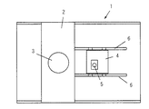
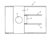
図1は、請求項1乃至5に記載の発明に係る実施例による光ピックアップ装置を適用した光ディスク装置の要部構成を示す模式図であり、同図に示す要部は、光ディスク装置の一つであるDVDレコーダに内蔵される光ピックアップ装置のドライブ機構(ローディングユニット)に相当している。 FIG. 1 is a schematic diagram showing a configuration of a main part of an optical disk device to which an optical pickup device according to an embodiment of the present invention is applied. The main part shown in FIG. This corresponds to a drive mechanism (loading unit) of an optical pickup device built in the DVD recorder.
同図において符号1は、ローディングユニットの外装部であり、内部には、クランプホルダー2が固定されている。クランプホルダー2は、光ディスクの回転駆動を行うスピンドルモータに光ディスクを固定保持するためのクランプ3を支持する部材であり、図示しないが光ディスクを搭載可能なトレイが外部に引き出された後も定位置にてクランプ3を保持するようになっている。
In the figure,
図1において符号4は光ピックアップ装置を構成するピックアップハウジングであり、光ディスクに対向するレンズ面を備えた対物レンズ5を備えている。
ピックアップハウジング4は、光ディスクの径方向に軸方向を有する支持シャフト6に沿って移動することができ、光ディスク面上の情報を読み書き動作を実行する。
In FIG. 1,
The
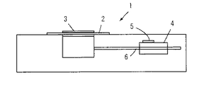
図2は、図1に示したドライブ機構の側面視による図であり、同図において、ピックアップハウジング4は、支持シャフト6に沿って図示しないシークモータの駆動により移動することができる。図2に示す状態は、ピックアップハウジング4が図示しない光ディスクと対向する位置に移動した状態であり、この状態ではピックアップハウジング4に装備されている対物レンズ5が剥き出しの状態となり、外部に露出されている。
FIG. 2 is a side view of the drive mechanism shown in FIG. 1, in which the
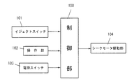
図3は、ピックアップハウジング4の移動を行わせるための制御部100の構成を説明するためのブロック図であり、同図において、制御部100は、光ピックアップとしての条件の一部であるフォーカシングやトラッキング制御および読み取り信号処理などを行う部分であり、本実施例と関連する部材として入力側には、トレイの引き出し指令を出力するイジェクトスイッチ101,読み書き処理終了時を検知する操作部102および電源スイッチ103が接続され、出力側にはシークモータの駆動部104が接続されている。
FIG. 3 is a block diagram for explaining the configuration of the
制御部100では、イジェクトスイッチ101による引き出し指令、読み書き終了信号あるいは電源スイッチ103の投入時に行われる初期化指令が入力されると、ピックアップハウジング4の位置を検知して強制的に光ディスクの最内周に位置させてクランプホルダー2により対物レンズ5を保護するようになっている。
つまり、トレイの引き出し指令が出されると、トレイの引き出しに必要な処理である、読み書き処理の終了作業やデータ転送処理の終了作業が行われ、これら各作業が終了すると図示しないロック機構を解除してトレイを外部に引き出すための処理を行うとともに、ピックアップハウジング4を対物レンズ5の保護位置に向け移動させる。
In the
In other words, when a tray pull-out command is issued, a read / write processing end operation and a data transfer processing end operation, which are processes necessary for the tray pull-out, are performed, and when these operations are completed, a lock mechanism (not shown) is released. Then, a process for pulling out the tray is performed, and the
対物レンズ5の保護位置は、本実施例の場合、光ディスク装置に既存構成部材として備えられているクランプホルダーの占有領域が用いられる。この結果、ピックアップハウジング4はクランプホルダー2の占有領域内に移動することにより、対物レンズ5の上方がクランプホルダー2によって覆われることになり、対物レンズ5への接触を回避できるようになる。制御部100では、上述した作業終了時に一旦、ピックアップハウジング4の位置をシークモータの初期状態からの回転方向および回転量により判別し、光ディスクの最内周、つまりスピンドルモータに最も近い位置にない場合に最内周の位置に設けてあるクランプホルダー2の位置に向けピックアップハウジング4を移動させるようになっている。
In this embodiment, the protection position of the
このような処理は、読み書き終了時あるいは電源投入時の初期化処理時に同様に行われる。 Such processing is similarly performed at the time of completion of reading / writing or initialization processing at power-on.
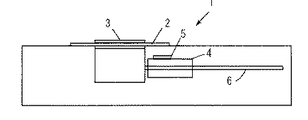
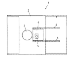
図4は、ピックアップハウジング4が光ディスクの最内周に位置してクランプホルダー2の占有領域内に位置している状態を示しており、図5は図4に示した状態を平面視的に示す図である。ピックアップハウジング4が光ディスクの最内周に位置する場合には、クランプホルダー2により少なくとも対物レンズ4の上方が覆われるようになっているが、これに限らず、図6に示すように、平面視において光ディスクの最内周に位置した場合のピックアップハウジング4の全部がクランプホルダー2に覆われるようにクランプホルダー2の大きさを設定することも可能である。
FIG. 4 shows a state in which the
次に、制御部100の作用について説明する。
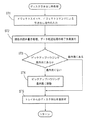
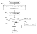
図7は、制御部100の動作を説明するためのフローチャートであり、同図において、イジェクトスイッチ101からのオン信号あるいはこれによるイジェクトコマンドによりトレイを外部に引き出す指令が入力されると(ST1)、現在行っているデータの読み書き処理あるいはデータ転送処理の終了作業が実行される(ST2)。
各作業が終了すると、ピックアップハウジング4が最内周に位置しているかどうかが判別され(ST3)、最内周にない場合には、シークモータを駆動してピックアップハウジング4を最内周に移動させて対物レンズ5をクランプホルダー2の占有領域内に位置決めする(ST4)。ステップST4の処理が終了すると、トレイの引き出し作業が実行される(ST5)。このような処理が実行されることにより、トレイを引き出す指令が出された場合にはピックアップハウジング4の位置を割り出した上で、対物レンズ5を光ディスクの最内周に位置させてクランプホルダー2により保護することができるので、対物レンズ5に対して不用意な接触や汚染物質の付着を防止することができる。
Next, the operation of the
FIG. 7 is a flowchart for explaining the operation of the
When each operation is completed, it is determined whether or not the
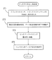
図8は、従来のトレイ引き出し時での処理を示すフローチャートであり、図7において符号ST1,ST2で示した内容の処理が同様に実行された後、トレイが引き出される。このため、図4に示した本実施例の処理と違って、トレイが引き出されるときにはピックアップハウジングはステップST2の内容処理を終了した位置で止まるだけで、光ディスクの最内周に向けて強制的な移動がない。このため、ピックアップハウジングの位置によっては対物レンズ5が剥き出しのままとなり、トレイが引き出された際あるいは収納される際に浮遊物が付着したりあるいは接触する虞がある。
FIG. 8 is a flowchart showing a process when a conventional tray is pulled out, and after the processes having the contents indicated by reference numerals ST1 and ST2 in FIG. 7 are similarly executed, the tray is pulled out. Therefore, unlike the processing of the present embodiment shown in FIG. 4, when the tray is pulled out, the pickup housing only stops at the position where the content processing of step ST2 is completed, and is forced toward the innermost periphery of the optical disc. There is no movement. For this reason, depending on the position of the pickup housing, the
次に実施例の要部についての変形例を説明する。
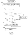
図9は、トレイが引き込まれる場合の処理に関する従来例を説明するためのフローチャートであり、同図において、イジェクトスイッチあるいはロードコマンドによるトレイの引き込み指令が出されると(ST10)、トレイが引き込み操作される(ST11)。
トレイが光ディスク装置内に引き込まれると、トレイ上に光ディスクが搭載されているかどうかが判別され(ST12)、光ディスクが搭載されている場合にはピックアップハウジングが通常のマウント動作が実行され(ST13)、搭載されていない場合にはピックアップハウジングは現段階の位置で待機動作を実行される(ST14)。
Next, a modification of the main part of the embodiment will be described.
FIG. 9 is a flowchart for explaining a conventional example regarding processing when a tray is pulled. In FIG. 9, when a tray pulling command is issued by an eject switch or a load command (ST10), the tray is pulled. (ST11).
When the tray is pulled into the optical disc apparatus, it is determined whether or not the optical disc is mounted on the tray (ST12). When the optical disc is mounted, the pickup housing performs a normal mounting operation (ST13). If it is not mounted, the pickup housing performs a standby operation at the current position (ST14).
このような処理が実行されると、ピックアップハウジングは現段階での位置に止まることになり、対物レンズが剥き出しのままとなる状態もある。つまり、光ディスクの搭載状況を判別するのはピックアップを用いるのでなく、スピンドルモータの回転トルクが判別条件として用いられる。このため、ピックアップハウジングの位置に関係なく光ディスクが搭載されていない場合が判別されることになる。この結果、交換や保守点検作業などにおいて対物レンズに接触したりあるいは周辺からの浮遊物質の付着が発生する。 When such processing is executed, the pickup housing stops at the current position, and the objective lens may remain exposed. In other words, the optical disk mounting status is not determined by using a pickup, but the rotational torque of the spindle motor is used as a determination condition. For this reason, the case where the optical disk is not mounted is determined regardless of the position of the pickup housing. As a result, the object comes into contact with the objective lens or the adhering floating substance from the periphery is generated during replacement or maintenance.
本実施例においては、トレイの引き込み時においてもピックアップハウジングの位置を検知して対物レンズを保護するようになっている。
図10は、この場合の制御部100の作用を説明するためのフローチャートであり、同図において、図10におけるステップST12において光ディスクが搭載されていないと判断した場合には、ピックアップハウジング4の位置が割り出され(ST15)、最内周に位置していない場合には最内周に向けて移動される(ST16)。このような処理により、引き込まれたトレイ上に光ディスクが搭載されていない場合においてピックアップハウジング4の対物レンズ5が剥き出しになることがないので、接触や汚損物質の付着を確実に防止することができる。
In this embodiment, the objective lens is protected by detecting the position of the pickup housing even when the tray is retracted.
FIG. 10 is a flowchart for explaining the operation of the
以上のような実施例においては、クランプホルダーという既存構成部材を対物レンズの保護部として利用することができるので、特別な保護構造を付設することがなく、簡易な構成によるレンズ保護が可能となる。 In the embodiment as described above, since the existing component member called the clamp holder can be used as the protective part of the objective lens, it is possible to protect the lens with a simple configuration without providing a special protection structure. .
次に、請求項6および7記載の発明に関する実施例について説明する。
本実施例は、光ディスクを搭載するトレイのみが引き出される構成ではなく、ピックアップを含むアクチュエータをはじめとする各部材がともにシャーシに相当するドロワに組み込まれ、ドロワ自体が引き出し操作される構成を対象としている。
Next, embodiments relating to the inventions of
This embodiment is not a configuration in which only the tray on which the optical disk is mounted is drawn, but a configuration in which each member including an actuator including a pickup is incorporated in a drawer corresponding to the chassis, and the drawer itself is pulled out. Yes.
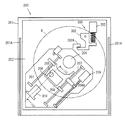
図11は、ドロワ自体が引き出し可能なスリムタイプと称される光ディスク装置の要部を示す平面図であり、同図において、光ディスク装置200の外装ケース201には、ガイドレール201Aにより外部に引き出す方向に摺動案内されるドロワ202が設けられており、ドロワ202の底板にはピックアップモジュール203が設けられている。
ピックアップモジュール203には、光ディスクDを回転駆動するスピンドルモータ204、対物レンズ205を備えたピックアップアクチュエータ206,を装備して光ディスクDの半径方向に並置されたガイド軸207によって摺動可能なピックアップハウジング208およびピックアップハウジング208を光ディスクの内周および外周に向けて摺動させる駆動部材としてのシークモータ209が設けられている。
シークモータ209からの駆動力はシークモータの出力軸に設けられているネジ部に噛み合うティース208Aを介してピックアップハウジング208に伝えられることによりピックアップハウジング208が往復動することができる。
FIG. 11 is a plan view showing a main part of an optical disk apparatus called a slim type that can be pulled out by the drawer itself. In FIG. 11, the
The pickup module 203 is equipped with a
The driving force from the seek
ドロワ202の一部には、外装ケース201側に設けられているロック解除機構300に係脱可能なドロワ爪202Aが設けられており、ドロワ爪202Aは、ロック解除機構300に有するソレノイド301によって作動されるイジェクトロックレバー302に係脱できるようになっている。
ロック解除機構300では、イジェクトロックレバー302が揺動可能に設けられており、ソレノイド301の励磁動作に応じてドロワ爪202Aに対する係合状態を解除できるようになっている。
A part of the
In the
図11は、ドロワ202が外装ケース201内に引き込まれた状態を示し図12は、ドロワ202が外装ケース201から外部に引き出された状態をそれぞれ示している。
FIG. 11 shows a state in which the
図11および図12においてドロワ202には、光ディスクDの最外周よりも外側の位置に対物レンズの保護部310が設けられている。
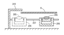
保護部310は、図13に示すように、光ディスクDの最外周よりも外側の位置に直立させた側面視形状が倒立L字状のカバー部材であり、対物レンズ206の上方を覆うことができるように、光ディスクDの最外周近傍に向けて張り出している。
11 and 12, the
As shown in FIG. 13, the
本実施例では、対物レンズ205の保護が必要な時期において強制的に保護部310に向けてピックアップハウジング208が移動され、この移動に関する制御条件は、図3に示した制御部100に適用される条件と同様である。
In the present embodiment, the
本実施例は、以上のような構成において、ピックアップハウジング208は、光ディスクDが搭載されていないときや電源投入時あるいはイジェクト時さらには、例えば、図13において実線で示すように光ディスクDの外周内に位置している場合、図13において二点鎖線で示すように、読み書き終了時にシークモータ209が動作することにより強制的に保護部310に向けて移動させられる。これにより、対物レンズ205の上方は、保護部310を構成するカバー部材で覆われることになるので、対物レンズ205への接触や汚損物質の付着が防止される。
In this embodiment, the
次に請求項8乃至10記載の発明にかかる実施例について説明する。
本実施例は、対物レンズの保護部を保護すべき位置に移動したピックアップハウジングによって駆動する構成を特徴としている。
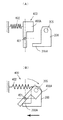
図14は、対物レンズの保護部400とピックアップハウジング208との関係を説明するための図であり、同図において、対物レンズの保護部400は、ピックアップモジュール203側において揺動可能に支持されて対物レンズ205の上方を覆うことができる方向の移動する習性が付与されている。
本実施例では、図14(A)に示すように、保護部400が支持ピン401を支点として回動可能な片部材が用いられるカバー部材400Aで構成されており、支持ピン401を挟んだ回動端の一方には、ピックアップモジュール203の不動部との間に設けられたバネなどの弾性体402が設けられて対物レンズ205から離間して対物レンズ205から外れる位置に移動する方向の回動習性が付与されている。
Next, embodiments according to the eighth to tenth aspects of the present invention will be described.
This embodiment is characterized in that it is driven by a pickup housing that has been moved to a position where the protective part of the objective lens is to be protected.
FIG. 14 is a diagram for explaining the relationship between the objective
In the present embodiment, as shown in FIG. 14A, the
保護部400の回動端の他方は、ピックアップハウジング208の移動路中に進出しており、ピックアップハウジング208側に設けられている作動片208Aに干渉できる構成とされている。
The other rotation end of the
本実施例では、ピックアップハウジング208が光ディスクと対向する位置にあるときには、カバー部材400Aが弾性体402の付勢により対物レンズ205から外れる位置に移動しており、この位置は図示しない係止部によって位置決めされている。
In this embodiment, when the
一方、ピックアップハウジング208が保護部400に向けて移動すると、図14(B)に示すように、カバー部材400Aの移動路中に進入している回動端の他方がピックアップハウジング208の片部208Aと干渉することによりカバー部材400Aが対物レンズ205を覆う向きに回動する。これにより対物レンズ205は、カバー部材400Aにより上方を覆われることで接触や汚損物質の付着を防止されることになる。
On the other hand, when the
本実施例においては、回動部材であるカバー部材400Aの回動が移動する既存構成部材であるピックアップハウジング208を利用するだけで済むので、対物レンズの保護のための特別な構造部品を要しないで済む。
In the present embodiment, it is only necessary to use the
1 光ピックアップ装置のドライブ機構に用いられる外装部
2 クランプホルダー
3 クランプ
4 ピックアップハウジング
5,205 対物レンズ
100 制御部
101 イジェクトスイッチ
102 操作部
103 電源スイッチ
200 光ディスク装置
202 ドロワ
203 ピックアップモジュール
204 スピンドルモータ
206 ピックアップアクチュエータ
208 ピックアップハウジング
208A 片部
310,400 対物レンズの保護部
400A 片部材からなるカバー部材
401 支持ピン
402 弾性体
DESCRIPTION OF
Claims (10)
上記光ディスクを回転駆動するスピンドルモータに上記光ディスクを固定するクランプを支持するためのクランプホルダーの占有領域内と該占有領域から上記光ディスクに対する走査領域へと移動させるための移動手段とを備え、
上記移動手段は、上記光ディスクを外部に引き出す際または光ディスクに対する書き込みあるいは再生終了時のいずれかの時期に上記レンズを上記クランプホルダーの占有領域内に位置させることを特徴とする光ピックアップ装置。 In an optical pickup device comprising a lens facing an optical disc, and having a configuration capable of scanning by moving the lens in an inner circumferential direction and an outer circumferential direction of the optical disc.
A clamp motor for supporting a clamp for fixing the optical disk to a spindle motor that rotationally drives the optical disk, and a moving means for moving from the occupied area to a scanning area for the optical disk,
The optical pickup apparatus characterized in that the moving means positions the lens in an occupied area of the clamp holder when the optical disk is pulled out or at the end of writing or reproduction on the optical disk.
上記移動手段は、上記光ディスクが搭載されるトレイが引き込まれる際に該光ディスクが搭載されていない場合に上記レンズの位置を上記クランプホルダーの占有領域内に設定することを特徴とする光ピックアップ装置。 The optical pickup device according to claim 1,
The optical pickup device according to claim 1, wherein the moving means sets the position of the lens within an occupied area of the clamp holder when the optical disk is not loaded when the tray on which the optical disk is loaded is pulled.
上記移動手段は、電源をオンされたときの所期化動作を行う際に上記光ディスクが搭載されていない場合に上記レンズの位置を上記クランプホルダーの占有領域内に設定することを特徴とする光ピックアップ装置。 The optical pickup device according to claim 1 or 2,
The moving means sets the position of the lens within the occupation area of the clamp holder when the optical disk is not mounted when performing an expected operation when the power is turned on. Pickup device.
上記クランプホルダーは、上記光ディスクの最内周位置に上記光ピックアップが位置している場合に光ピックアップ装置の全体を覆うことができる大きさを備えていることを特徴とする光ディスク装置。 The optical disc apparatus according to claim 4, wherein
The optical disc apparatus, wherein the clamp holder has a size capable of covering the entire optical pickup device when the optical pickup is located at the innermost peripheral position of the optical disc.
光ディスクの引き出し指令が行われた場合に上記レンズを上記光ディスクと対向しない位置に設けてある保護部により覆い隠せる構成を備えていることを特徴とする光ディスク装置。 As a scanning mechanism for the optical disk, an optical pickup actuator unit including a lens unit, a pickup housing unit holding the actuator unit and incorporating an optical component such as a semiconductor laser, and two rail shafts holding the pickup housing unit The pickup module unit, which holds the rail shaft, the spindle motor that is the optical disk rotation drive means, the seek motor that is the lens movement means, and the motor board, is fixed. A drawer unit, a lock mechanism for holding the entire drawer unit inside the drive housing, a mechanism for releasing the lock mechanism, an eject button unit for recognizing an eject operation, a circuit board on which an electronic component for signal processing is mounted, and an exterior component This is equipped with In each section an optical disk apparatus which is capable of drawer construction in the outside together with the optical disk,
An optical disc apparatus comprising: a configuration in which the lens can be covered by a protective portion provided at a position not facing the optical disc when an optical disc withdrawal command is issued.
上記レンズの保護部は、上記光ディスクの最外周位置よりも外側の位置で上記外装部品の一部に設けられて上記レンズの上方に張り出す構成であることを特徴とする光ディスク装置。 The optical disk apparatus according to claim 6, wherein
The optical disk apparatus according to claim 1, wherein the lens protection unit is provided on a part of the exterior component at a position outside the outermost peripheral position of the optical disk and projects over the lens.
上記レンズの保護部は、上記レンズの上方を覆うことができる方向の移動習性を付与されたカバー部材を備え、該カバー部材は、上記ピックアップハウジング部が上記シークモータにより光ディスクの外周に向け移動した際に作動されることにより上記レンズの上方を覆う位置に移動する構成であることを特徴とする光ディスク装置。 The optical disk apparatus according to claim 7, wherein
The protective portion of the lens includes a cover member imparted with a movement habit in a direction that can cover the upper side of the lens, and the cover member is moved toward the outer periphery of the optical disk by the seek motor. An optical disk apparatus, wherein the optical disk apparatus is configured to move to a position covering the upper side of the lens by being actuated at the time.
上記カバー部材は、上記レンズの上方を覆う位置と該レンズの上方から外れる位置とに変位可能であり、通常、上記レンズの上方から外れる位置への変位習性が付与され、上記ピックアップハウジングとの干渉時に上記変位習性に抗して上記レンズの上方を覆う位置に変位する構成であることを特徴とする光ディスク装置。 The optical disk apparatus according to claim 8, wherein
The cover member is displaceable between a position covering the upper side of the lens and a position deviating from the upper side of the lens. Usually, the cover member is given a displacement behavior to a position deviating from the upper side of the lens and interferes with the pickup housing. An optical disc apparatus characterized in that the optical disc apparatus is sometimes displaced to a position covering the upper side of the lens against the displacement behavior.
上記カバー部材は、支点を挟んで回転可能な片部材で構成され、該支点を挟んで一方の回動端には上記レンズの上方から外れる向きの変位習性を付与する付勢部材が設けられ、他方の回動端が上記ピックアップハウジングと干渉する部位とされ、該回動端の他方がピックアップハウジングと干渉した際に回動することにより回動端の一方で上記レンズの上方を覆う構成であることを特徴とする光ディスク装置。
The optical disk device according to claim 8 or 9,
The cover member is composed of a single member that is rotatable with a fulcrum interposed therebetween, and a biasing member that provides a displacement behavior in a direction away from the upper side of the lens is provided at one rotation end with the fulcrum interposed therebetween, The other rotation end is a part that interferes with the pickup housing, and the other rotation end covers the upper side of the lens by rotating when the other one interferes with the pickup housing. An optical disc device characterized by the above.
Priority Applications (1)
| Application Number | Priority Date | Filing Date | Title |
|---|---|---|---|
| JP2004105689A JP2005293694A (en) | 2004-03-31 | 2004-03-31 | Optical pickup device and optical disk device |
Applications Claiming Priority (1)
| Application Number | Priority Date | Filing Date | Title |
|---|---|---|---|
| JP2004105689A JP2005293694A (en) | 2004-03-31 | 2004-03-31 | Optical pickup device and optical disk device |
Publications (1)
| Publication Number | Publication Date |
|---|---|
| JP2005293694A true JP2005293694A (en) | 2005-10-20 |
Family
ID=35326466
Family Applications (1)
| Application Number | Title | Priority Date | Filing Date |
|---|---|---|---|
| JP2004105689A Pending JP2005293694A (en) | 2004-03-31 | 2004-03-31 | Optical pickup device and optical disk device |
Country Status (1)
| Country | Link |
|---|---|
| JP (1) | JP2005293694A (en) |
Cited By (1)
| Publication number | Priority date | Publication date | Assignee | Title |
|---|---|---|---|---|
| JP2010145988A (en) * | 2008-12-17 | 2010-07-01 | Korea Electronics Telecommun | Tunable diffraction grating apparatus |
-
2004
- 2004-03-31 JP JP2004105689A patent/JP2005293694A/en active Pending
Cited By (1)
| Publication number | Priority date | Publication date | Assignee | Title |
|---|---|---|---|---|
| JP2010145988A (en) * | 2008-12-17 | 2010-07-01 | Korea Electronics Telecommun | Tunable diffraction grating apparatus |
Similar Documents
| Publication | Publication Date | Title |
|---|---|---|
| CN1206647C (en) | Medium automatic changover device and medium carrying tray | |
| US5473593A (en) | Compact disk transport tray moved by a disk reading mechanism | |
| CN1392559A (en) | Disk cassette | |
| JPH07320359A (en) | Optical disc cartridge and optical disc drive device | |
| JP2005293694A (en) | Optical pickup device and optical disk device | |
| CN100476971C (en) | Disk drive device and electronic apparatus | |
| CN1855265B (en) | Disk drive device and electronic apparatus | |
| JP4254620B2 (en) | Disk drive device | |
| JP3822621B2 (en) | Disk unit | |
| JP2009037710A (en) | Disk drive device | |
| US20080316875A1 (en) | Optical Disc Apparatus for Accessing a Plurality of Optical Discs and Operating Method thereof | |
| US8015575B2 (en) | Disk device with insertion slot capable of preventing double loading of disks | |
| US20080282270A1 (en) | Disc drive adapted to be downsized | |
| US7652956B2 (en) | Disc drive operative with both large-diameter and small-diameter optical discs, and method of controlling same | |
| JP4315067B2 (en) | Disk drive device | |
| JP4229012B2 (en) | Disk drive device | |
| JP4525471B2 (en) | Disk drive device | |
| JP4613529B2 (en) | Disk drive device | |
| JP2510106B2 (en) | Optical disk drive | |
| CN100464372C (en) | disk drive | |
| JP4525633B2 (en) | Disk drive device and disk recording and / or playback device | |
| JP2000182308A (en) | Optical disk drive | |
| JP2008123628A (en) | Optical disk device | |
| JP5246202B2 (en) | Disk drive device | |
| KR100268588B1 (en) | Disc actuating device and method |