JP2005293864A - Surface illumination device and display device using the device - Google Patents
Surface illumination device and display device using the device Download PDFInfo
- Publication number
- JP2005293864A JP2005293864A JP2004102789A JP2004102789A JP2005293864A JP 2005293864 A JP2005293864 A JP 2005293864A JP 2004102789 A JP2004102789 A JP 2004102789A JP 2004102789 A JP2004102789 A JP 2004102789A JP 2005293864 A JP2005293864 A JP 2005293864A
- Authority
- JP
- Japan
- Prior art keywords
- light source
- point light
- guide plate
- point
- light guide
- Prior art date
- Legal status (The legal status is an assumption and is not a legal conclusion. Google has not performed a legal analysis and makes no representation as to the accuracy of the status listed.)
- Granted
Links
Images
Landscapes
- Non-Portable Lighting Devices Or Systems Thereof (AREA)
- Planar Illumination Modules (AREA)
- Illuminated Signs And Luminous Advertising (AREA)
Abstract
【課題】 従来の面照明装置では、導光板の凹部には、全て点光源を設置していたので、明るさを変更するためには、点光源を設置する凹部の数の相違する導光板に変更する必要があった。
【解決手段】 本発明に係る面照明装置は、点光源を設置した基板と、点光源を配置する点光源用の凹部を側面側に設けた導光板とを備え、導光板の光源用の凹部の数を、配置する点光源の数よりも多くし、基板の点光源を導光板の対応する点光源用の凹部に配置したものである。
【選択図】 図1
PROBLEM TO BE SOLVED: To change the brightness of a light guide plate having a different number of concave portions in which point light sources are installed in order to change the brightness, since the conventional surface illumination device has all the point light sources installed in the concave portions of the light guide plate. There was a need to change.
A surface illumination device according to the present invention includes a substrate on which a point light source is installed, and a light guide plate in which a concave portion for a point light source in which the point light source is arranged is provided on a side surface, and the concave portion for the light source of the light guide plate. Is more than the number of point light sources to be arranged, and the point light sources of the substrate are arranged in the corresponding concave portions for the point light sources of the light guide plate.
[Selection] Figure 1
Description
本発明は、点光源を用いた面照明装置及び該面照明装置を用いた誘導灯、液晶表示装置等の表示装置に関するものである。 The present invention relates to a surface illumination device using a point light source and a display device such as a guide light or a liquid crystal display device using the surface illumination device.
従来の面照明装置は、側面に点光源装置凹部を複数個設けた透明板からなる導光板において、該側面の上記凹部と凹部との間に略三角形状の切れ込みを設けた点光源を用いた面照明装置用導光板を使用するものである(例えば、特許文献1参照)。
特許文献1の面照明装置は、導光板の凹部に全て点光源を設置していた。いいかえると、点光源と同じ数の凹部を設けていた。
そこで、明るさを変更するためには、導光板を変え、点光源を設置する凹部の数の相違する導光板に変更する必要があった。
In the surface illumination device of
Therefore, in order to change the brightness, it is necessary to change the light guide plate to a light guide plate having a different number of recesses in which the point light sources are installed.
本発明は、上記のような課題を解決するためになされたもので、導光板を変更しないで、明るさを変えることができる点光源を用いた面照明装置を得ることを目的とする。
また、明るさが均一な点光源を用いた面照明装置を得ることを目的とする。
また、この面照明装置を用い、目的に応じて容易に明るさを変えることができ、表示面の明るさが均一な表示装置を得ることを目的とする。
The present invention has been made to solve the above-described problems, and an object of the present invention is to obtain a surface illumination device using a point light source that can change brightness without changing a light guide plate.
It is another object of the present invention to obtain a surface illumination device using a point light source with uniform brightness.
It is another object of the present invention to provide a display device that can easily change the brightness according to the purpose by using this surface illumination device and has a uniform display surface brightness.
本発明に係る点光源を用いた面照明装置は、点光源を設置した基板と、点光源を配置する点光源用の凹部を側面に沿って設けた導光板とを備え、導光板の光源用の凹部の数を、配置する点光源の数よりも多くし、基板の点光源を導光板の対応する点光源用の凹部に配置したものである。 The surface illumination device using the point light source according to the present invention includes a substrate on which the point light source is installed, and a light guide plate provided with a concave portion for the point light source in which the point light source is disposed along the side surface. The number of the concave portions is larger than the number of the point light sources to be arranged, and the point light sources of the substrate are arranged in the corresponding concave portions for the point light sources of the light guide plate.
本発明に係る点光源を用いた面照明装置は、導光板の点光源挿入用の凹部の数を、配置する点光源の数よりも多くし、基板の点光源を導光板の対応する点光源用の凹部に配置したので、同一の導光板で点光源を設置した基板を交換することにより、点光源の数を変えることができ、容易に照射面の明るさを変えることができる。 In the surface illumination device using the point light source according to the present invention, the number of the concave portions for inserting the point light source of the light guide plate is larger than the number of the point light sources to be arranged, and the point light source of the substrate is the corresponding point light source of the light guide plate Therefore, the number of point light sources can be changed and the brightness of the irradiated surface can be easily changed by replacing the substrate on which the point light sources are installed with the same light guide plate.
実施の形態1.
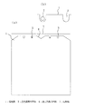
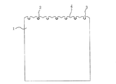
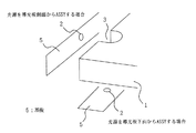
図1は、本発明の実施の形態1における点光源を用いた面照明装置を示す図であり、図1(a)は、その平面図であり、図1(b)は、凹部中の点光源を示す図である。図2は、同じく、点光源を用いた面照明装置の点光源の数を増やした導光板を示す平面図であり、図3は、同じく、点光源を用いた面照明装置の導光板の凹部に点光源を配置する方法を説明する図である。
これらの図において、アクリル板等の透明板である導光板1の一側面に複数の光源用の凹部3を形成する。この光源用の凹部3の形状は、導光板1を側端から平行に切り込み先端を半円状にしたものであり、切り込みの幅、半円の大きさは、発光ダイオード等の点光源2が容易に収容できるように点光源2の大きさに合せる。また、同形状が望ましいが、点光源2が配置できれば、異形状が混在してもよい。
FIG. 1 is a diagram showing a surface illumination device using a point light source according to
In these drawings, a plurality of
図1の導光板1は、左右対称に4個の同形状の光源用の凹部3を設け、そのうち、中央の2個に点光源2を配置した例である。導光板1の点光源2を設置する側面に対向して、反射板7を設ける。また、中央の2個の点光源2間に点光源2を設置しない逆三角形の凹部4を設けている。
図1には記載を省略しているが、通常は、導光板1の前面の照射面側に拡散板、及び導光板1の底面側に反射板を設ける。拡散板で、照射面から出射光が均一化され、また、底面側に反射板により、導光板1の底面側からの光の損失が防止できる。
The
Although not shown in FIG. 1, normally, a diffusion plate is provided on the irradiation surface side of the front surface of the
導光板1の光源用の凹部3に点光源2を配置する方法は、図3に示すように、基板5に所定数の点光源2を導光板1の光源用の凹部3に対応して設ける。点光源2を設置した基板5を導光板1の側面側に設置し、点光源2を対応する導光板1の光源用の凹部3に配置する。この場合は、反射板3は、基板5の点光源2を設置している面を反射板とする。即ち、アルミ基板に白色塗料を塗布する等完全拡散反射面に近い面を形成するようにする。
また、導光板1の光源用の凹部3に点光源2を配置する方法は、所定数の点光源2を導光板1の光源用の凹部3に対応して設けた基板5を導光板1の下部に設置し、同じく点光源2を対応する導光板1の光源用の凹部3に配置する。この場合は、導光板1の側面には、基板5とは別に反射板7を設ける。
反射板7により、点光源2の出射光は、有効に導光板1に入射し、照射面から出射する。
The method of disposing the
Further, the method of disposing the
Due to the
図1の導光板1では、外側の2個の光源用の凹部3にも点光源2を追加することにより、明るさを増加することができる。点光源2の数を変えるのは、点光源2を設置した基板5を取り替える。
図2は、点光源2の数を更に増やすため、光源用の凹部3の数を増やした導光板1の例である。この場合は、実線で示した3個の点光源2による3灯照射と点線で示した4個の点光源2を追加し、中央の実線の1個を削除して6灯照射とするものである。この場合も点光源2を設置した基板5を交換する。点光源用の凹部3間には、逆三角形の凹部4を設けている。
In the
FIG. 2 shows an example of the
本実施の形態の点光源を用いた面照明装置では、同一の導光板1で基板5を交換することにより、点光源2の数を変えることができ、容易に照射面の明るさを変えることができる。
そこで、誘導灯などの同一サイズで、異なる光量に規定された器具(例えば、B級誘導灯のBL形、BH形等)に点光源を用いた面照明装置を使用する場合、点光源2付きの基板5を変えるだけで、同一の導光板1で対応できる。
In the surface illumination device using the point light source of the present embodiment, the number of the
Therefore, when a surface illumination device using a point light source is used for an appliance (for example, a BL type B class, a BH type B-class induction light, etc.) of the same size, such as a guide light, that is specified for different light amounts, a
本実施の形態の点光源を用いた面照明装置は、光源用の凹部3のうち、点光源2を設置しない光源用の凹部3は、照射面の明るさを均一化するのに有効である。
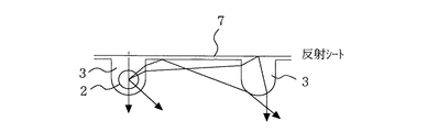
図4に示すように、点光源用の凹部3の点光源2からの出射光は、放射状に出るが、このうち点光源2を設置していない点光源用の凹部3に到達した光は、表面で全反射または点光源用の凹部3内を経て、側面または底面に設けた反射板7により反射され、再度点光源用の凹部3から導光板1内に入射する。このように光源を配置していない点光源用の凹部3は、光源を配置していないにもかかわらず点光源用の凹部3内から光が発せられるように光の進行方向を変化させることができるため、点光源用の凹部3は、擬似光源として機能し、光源を多数用いた場合と同様に明るさを均一化する作用がある。
特に、反射板7として拡散反射板を用いると、ランダムに反射した光が、点光源用の凹部3から導光板1内に再入射されるため、光源から全方向に光を出射する光源を配置した点光源用の凹部3と同様な光の広がりを得ることができるため好ましい。
さらに、点光源2を設置しない光源用の凹部3は、点光源2を設置した光源用の凹部3と同形状とすることにより、擬似光源として同様の出射パターンとなり、照射面の明るさの均一化にはより有効である。
In the surface illumination device using the point light source of the present embodiment, among the
As shown in FIG. 4, the light emitted from the
In particular, when a diffuse reflection plate is used as the
Further, the
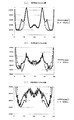
図5、図6にモンテカルロ法によるシミュレーション結果を示す。
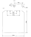
図5は、導光板1及び設置した点光源2を示す。これは、図1と同じものであり、各寸法は、記載の通りである。
図6(a)、(b)、(c)は、それぞれ、導光板1の照射面の光源用の凹部3の頂部(半円の先端)からの距離が、5mm、10mm、20mm位置で、横に200mmの全幅(横軸)にわたる明るさの均一性(縦軸に照度の相対値を表示)をみたものである。実線が図5の導光板1であり、点線は、図5で両外側の光源用の凹部3がない場合である。
これらの3図ともに点光源2が配置されない光源用の凹部3がある方が均一性が増しているのがわかる。
また、点光源2を設置した凹部3間または点光源2を設置した凹部3と設置しない凹部3間に逆三角形の凹部4を設けることにより、導光板1の照射面の明るさを均一化できる。
FIG. 5 and FIG. 6 show simulation results by the Monte Carlo method.
FIG. 5 shows the
6 (a), (b), and (c), respectively, the distance from the top of the light source recess 3 (the tip of the semicircle) on the irradiation surface of the
In these three figures, it can be seen that the uniformity is increased when the light source recess 3 in which the
Moreover, the brightness of the irradiation surface of the
本実施の形態の点光源を用いた面照明装置は、導光板1の光源用の凹部3の形状を全て同形状とすることにより、光源用凹部3で、点光源2を配置しない光源用凹部3は、擬似光源として機能し、光源用の凹部3に配置した点光源2と同様な光出射パターンとなり、照射面の明るさの均一化に効果が大きい。
In the surface illumination device using the point light source according to the present embodiment, all the
また、本実施の形態の点光源を用いた面照明装置は、点光源2を配置した光源用の凹部3に点光源2を配置しない点光源用の凹部3を隣接させることにより、隣接させた点光源2を配置しない点光源用の凹部3は、擬似光源として、照射面の明るさの均一化に有効に機能する。
Moreover, the surface illumination device using the point light source according to the present embodiment is made adjacent by making the
実施の形態2.
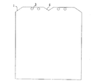
図7は、実施の形態2の点光源を用いた面照明装置の導光板の平面図である。本実施の形態の点光源を用いた面照明装置は、導光板1の点光源用の凹部3を導光板1の側面側の端部に形成した一列の穴とし、この穴に点光源2を配置する。その他の構成は、実施の形態1と同様である。また、得られる効果も同様である。
本導光板1の場合の点光源2の配置は、図3に示す点光源2を設置した基板5を導光板1の下部に設置して行う。
FIG. 7 is a plan view of the light guide plate of the surface illumination device using the point light source of the second embodiment. In the surface illumination device using the point light source according to the present embodiment, the point light source
The arrangement of the point
実施の形態3.
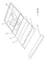
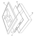
図8は、表示板組立部を示す分解斜視図であり、図9は、表示装置を示す分解斜視図である。本実施の形態の表示装置は、実施の形態1、2に記載の面照明装置の導光板1の照射面側に表示板10又は電気信号に応じて表示情報を可変できる液晶表示板等を配置したものである。
FIG. 8 is an exploded perspective view showing the display panel assembly portion, and FIG. 9 is an exploded perspective view showing the display device. In the display device of the present embodiment, a
図8に示すように、表示組立部13は、導光板1の背面側に反射板7を配置し、また、照射面側に、順次、照射面側に光を配光する光学板9、拡散板8、表示手段である表示板10(例えば、ピクトグラムの印刷された表示板)を配置し、これらを枠11に収納し、上部を反射板(点光源2の光を導光板1の下方に反射する反射板)付きのカバー12で覆い形成される。
このようにして組立てた表示組立部13の上部の導光板1の光源用の凹部3に対応してカバー12の背面側に形成した光源穴から基板5に設置した点光源2を凹部3に配置する。これらを筐体15に、表示板組立部13が蓋になるように取付け、表示装置を形成する。なお、筐体15内には、駆動装置14を収容する。
本表示装置は、実施の形態1、2に記載の面照明装置の導光板1の照射面側に表示手段である表示板10又は液晶表示板等を配置したので、目的に応じて容易に明るさを変えることができ、また、表示面の明るさが均一な表示装置となる。
As shown in FIG. 8, the
The point
In the present display device, since the
実施の形態1、2、3においては、点光源2を導光板1の一側面に沿って設けているが、対向する二側面に沿って設けたり、また、三側面、さらに四側面に沿って設けてもよい。
In the first, second, and third embodiments, the point
1 導光板、3 点光源用の凹部、4 逆三角形の凹部、5 基板、7 反射板、10表示手段。
DESCRIPTION OF
Claims (7)
前記導光板の光源用の凹部の数を、配置する点光源の数よりも多くし、前記基板の点光源を前記導光板の対応する点光源用の凹部に配置したことを特徴とする点光源を用いた面照明装置。 A substrate provided with a point light source, and a light guide plate provided with a concave portion for the point light source for arranging the point light source along the side surface,
The number of concave portions for light sources of the light guide plate is larger than the number of point light sources to be arranged, and the point light sources of the substrate are arranged in corresponding concave portions for point light sources of the light guide plate. Surface lighting device using
The display means which modulates the light radiate | emitted from the said light-guide plate and provided the information on the irradiation surface side of the light-guide plate of the surface illuminating device of any one of Claims 1-6 was provided. Characteristic display device.
Priority Applications (1)
| Application Number | Priority Date | Filing Date | Title |
|---|---|---|---|
| JP2004102789A JP4302562B2 (en) | 2004-03-31 | 2004-03-31 | Surface illumination device and display device using the device |
Applications Claiming Priority (1)
| Application Number | Priority Date | Filing Date | Title |
|---|---|---|---|
| JP2004102789A JP4302562B2 (en) | 2004-03-31 | 2004-03-31 | Surface illumination device and display device using the device |
Publications (3)
| Publication Number | Publication Date |
|---|---|
| JP2005293864A true JP2005293864A (en) | 2005-10-20 |
| JP2005293864A5 JP2005293864A5 (en) | 2007-05-10 |
| JP4302562B2 JP4302562B2 (en) | 2009-07-29 |
Family
ID=35326588
Family Applications (1)
| Application Number | Title | Priority Date | Filing Date |
|---|---|---|---|
| JP2004102789A Expired - Lifetime JP4302562B2 (en) | 2004-03-31 | 2004-03-31 | Surface illumination device and display device using the device |
Country Status (1)
| Country | Link |
|---|---|
| JP (1) | JP4302562B2 (en) |
Cited By (2)
| Publication number | Priority date | Publication date | Assignee | Title |
|---|---|---|---|---|
| JP2009069580A (en) * | 2007-09-14 | 2009-04-02 | Pae:Kk | Nameplate |
| AT515853A1 (en) * | 2014-05-21 | 2015-12-15 | Ackutech AG | illuminated frames |
-
2004
- 2004-03-31 JP JP2004102789A patent/JP4302562B2/en not_active Expired - Lifetime
Cited By (3)
| Publication number | Priority date | Publication date | Assignee | Title |
|---|---|---|---|---|
| JP2009069580A (en) * | 2007-09-14 | 2009-04-02 | Pae:Kk | Nameplate |
| AT515853A1 (en) * | 2014-05-21 | 2015-12-15 | Ackutech AG | illuminated frames |
| AT515853B1 (en) * | 2014-05-21 | 2016-08-15 | Ackutech AG | illuminated frames |
Also Published As
| Publication number | Publication date |
|---|---|
| JP4302562B2 (en) | 2009-07-29 |
Similar Documents
| Publication | Publication Date | Title |
|---|---|---|
| US8262252B2 (en) | Illumination system | |
| KR100807605B1 (en) | Illumination system and display device using the same | |
| JP5920616B2 (en) | Direct type LED backlight device and liquid crystal display device using the same | |
| CN101275719B (en) | LED lighting device | |
| CN102498336B (en) | Light source device and surface lighting device using the light source device | |
| JP2006019141A (en) | Backlight and liquid crystal display device including the backlight | |
| JP2009199971A (en) | Lighting device | |
| JPWO2010004610A1 (en) | Light guide plate unit and lighting fixture using the light guide plate unit | |
| JP2006120594A (en) | Backlight device with reduced thickness | |
| JP4140710B2 (en) | Display device | |
| KR100708147B1 (en) | Light emitting cluster and direct light type back light unit and liquid display apparatus employing it | |
| EP1835226A1 (en) | Lighting equipment and lighting system | |
| KR20170035500A (en) | Backlight unit and display appratus having the same | |
| WO2010016320A1 (en) | Illuminating device and liquid crystal display device provided with the same | |
| AU2013326308A1 (en) | Improved LCD backlight display | |
| JP2004325959A (en) | LCD backlight device | |
| JP4701329B2 (en) | LIGHT SOURCE DEVICE AND LIGHTING DEVICE USING THE LIGHT SOURCE DEVICE | |
| JP4708440B2 (en) | Surface light source device | |
| JP4302562B2 (en) | Surface illumination device and display device using the device | |
| JP2005203346A (en) | Lighting device for display system | |
| KR20060115124A (en) | A light emitter for obtaining a uniform light distribution and a backlight unit using the light emitter | |
| JP5416268B1 (en) | High-reflection reflector light source | |
| JP2013182854A (en) | Lighting device and display device with the same | |
| JP4718144B2 (en) | Light source structure of internally illuminated bulletin board | |
| JP5854625B2 (en) | Light source device |
Legal Events
| Date | Code | Title | Description |
|---|---|---|---|
| A521 | Request for written amendment filed |
Free format text: JAPANESE INTERMEDIATE CODE: A523 Effective date: 20070320 |
|
| A621 | Written request for application examination |
Free format text: JAPANESE INTERMEDIATE CODE: A621 Effective date: 20070320 |
|
| A977 | Report on retrieval |
Free format text: JAPANESE INTERMEDIATE CODE: A971007 Effective date: 20080910 |
|
| A131 | Notification of reasons for refusal |
Free format text: JAPANESE INTERMEDIATE CODE: A131 Effective date: 20080916 |
|
| A521 | Request for written amendment filed |
Free format text: JAPANESE INTERMEDIATE CODE: A523 Effective date: 20081024 |
|
| TRDD | Decision of grant or rejection written | ||
| A01 | Written decision to grant a patent or to grant a registration (utility model) |
Free format text: JAPANESE INTERMEDIATE CODE: A01 Effective date: 20090414 |
|
| A01 | Written decision to grant a patent or to grant a registration (utility model) |
Free format text: JAPANESE INTERMEDIATE CODE: A01 |
|
| A61 | First payment of annual fees (during grant procedure) |
Free format text: JAPANESE INTERMEDIATE CODE: A61 Effective date: 20090422 |
|
| FPAY | Renewal fee payment (event date is renewal date of database) |
Free format text: PAYMENT UNTIL: 20120501 Year of fee payment: 3 |
|
| R150 | Certificate of patent or registration of utility model |
Free format text: JAPANESE INTERMEDIATE CODE: R150 Ref document number: 4302562 Country of ref document: JP Free format text: JAPANESE INTERMEDIATE CODE: R150 |
|
| FPAY | Renewal fee payment (event date is renewal date of database) |
Free format text: PAYMENT UNTIL: 20120501 Year of fee payment: 3 |
|
| FPAY | Renewal fee payment (event date is renewal date of database) |
Free format text: PAYMENT UNTIL: 20130501 Year of fee payment: 4 |
|
| FPAY | Renewal fee payment (event date is renewal date of database) |
Free format text: PAYMENT UNTIL: 20140501 Year of fee payment: 5 |
|
| R250 | Receipt of annual fees |
Free format text: JAPANESE INTERMEDIATE CODE: R250 |
|
| R250 | Receipt of annual fees |
Free format text: JAPANESE INTERMEDIATE CODE: R250 |
|
| R250 | Receipt of annual fees |
Free format text: JAPANESE INTERMEDIATE CODE: R250 |
|
| R250 | Receipt of annual fees |
Free format text: JAPANESE INTERMEDIATE CODE: R250 |
|
| R250 | Receipt of annual fees |
Free format text: JAPANESE INTERMEDIATE CODE: R250 |
|
| R250 | Receipt of annual fees |
Free format text: JAPANESE INTERMEDIATE CODE: R250 |
|
| R250 | Receipt of annual fees |
Free format text: JAPANESE INTERMEDIATE CODE: R250 |
|
| R250 | Receipt of annual fees |
Free format text: JAPANESE INTERMEDIATE CODE: R250 |
|
| EXPY | Cancellation because of completion of term |