JP2005293997A - Fuel cell power generation refrigeration system - Google Patents
Fuel cell power generation refrigeration system Download PDFInfo
- Publication number
- JP2005293997A JP2005293997A JP2004106584A JP2004106584A JP2005293997A JP 2005293997 A JP2005293997 A JP 2005293997A JP 2004106584 A JP2004106584 A JP 2004106584A JP 2004106584 A JP2004106584 A JP 2004106584A JP 2005293997 A JP2005293997 A JP 2005293997A
- Authority
- JP
- Japan
- Prior art keywords
- fuel cell
- power
- power generation
- refrigeration system
- vapor compression
- Prior art date
- Legal status (The legal status is an assumption and is not a legal conclusion. Google has not performed a legal analysis and makes no representation as to the accuracy of the status listed.)
- Granted
Links
Images




Classifications
-
- H—ELECTRICITY
- H01—ELECTRIC ELEMENTS
- H01M—PROCESSES OR MEANS, e.g. BATTERIES, FOR THE DIRECT CONVERSION OF CHEMICAL ENERGY INTO ELECTRICAL ENERGY
- H01M8/00—Fuel cells; Manufacture thereof
- H01M8/04—Auxiliary arrangements, e.g. for control of pressure or for circulation of fluids
- H01M8/04298—Processes for controlling fuel cells or fuel cell systems
- H01M8/04313—Processes for controlling fuel cells or fuel cell systems characterised by the detection or assessment of variables; characterised by the detection or assessment of failure or abnormal function
- H01M8/04537—Electric variables
- H01M8/04604—Power, energy, capacity or load
- H01M8/04619—Power, energy, capacity or load of fuel cell stacks
-
- F—MECHANICAL ENGINEERING; LIGHTING; HEATING; WEAPONS; BLASTING
- F25—REFRIGERATION OR COOLING; COMBINED HEATING AND REFRIGERATION SYSTEMS; HEAT PUMP SYSTEMS; MANUFACTURE OR STORAGE OF ICE; LIQUEFACTION SOLIDIFICATION OF GASES
- F25B—REFRIGERATION MACHINES, PLANTS OR SYSTEMS; COMBINED HEATING AND REFRIGERATION SYSTEMS; HEAT PUMP SYSTEMS
- F25B27/00—Machines, plants or systems, using particular sources of energy
-
- H—ELECTRICITY
- H01—ELECTRIC ELEMENTS
- H01M—PROCESSES OR MEANS, e.g. BATTERIES, FOR THE DIRECT CONVERSION OF CHEMICAL ENERGY INTO ELECTRICAL ENERGY
- H01M16/00—Structural combinations of different types of electrochemical generators
- H01M16/003—Structural combinations of different types of electrochemical generators of fuel cells with other electrochemical devices, e.g. capacitors, electrolysers
- H01M16/006—Structural combinations of different types of electrochemical generators of fuel cells with other electrochemical devices, e.g. capacitors, electrolysers of fuel cells with rechargeable batteries
-
- H—ELECTRICITY
- H01—ELECTRIC ELEMENTS
- H01M—PROCESSES OR MEANS, e.g. BATTERIES, FOR THE DIRECT CONVERSION OF CHEMICAL ENERGY INTO ELECTRICAL ENERGY
- H01M8/00—Fuel cells; Manufacture thereof
- H01M8/04—Auxiliary arrangements, e.g. for control of pressure or for circulation of fluids
- H01M8/04298—Processes for controlling fuel cells or fuel cell systems
- H01M8/04313—Processes for controlling fuel cells or fuel cell systems characterised by the detection or assessment of variables; characterised by the detection or assessment of failure or abnormal function
- H01M8/04537—Electric variables
- H01M8/04604—Power, energy, capacity or load
-
- H—ELECTRICITY
- H01—ELECTRIC ELEMENTS
- H01M—PROCESSES OR MEANS, e.g. BATTERIES, FOR THE DIRECT CONVERSION OF CHEMICAL ENERGY INTO ELECTRICAL ENERGY
- H01M8/00—Fuel cells; Manufacture thereof
- H01M8/04—Auxiliary arrangements, e.g. for control of pressure or for circulation of fluids
- H01M8/04298—Processes for controlling fuel cells or fuel cell systems
- H01M8/04694—Processes for controlling fuel cells or fuel cell systems characterised by variables to be controlled
- H01M8/04858—Electric variables
- H01M8/04925—Power, energy, capacity or load
-
- H—ELECTRICITY
- H01—ELECTRIC ELEMENTS
- H01M—PROCESSES OR MEANS, e.g. BATTERIES, FOR THE DIRECT CONVERSION OF CHEMICAL ENERGY INTO ELECTRICAL ENERGY
- H01M8/00—Fuel cells; Manufacture thereof
- H01M8/04—Auxiliary arrangements, e.g. for control of pressure or for circulation of fluids
- H01M8/04298—Processes for controlling fuel cells or fuel cell systems
- H01M8/04694—Processes for controlling fuel cells or fuel cell systems characterised by variables to be controlled
- H01M8/04858—Electric variables
- H01M8/04925—Power, energy, capacity or load
- H01M8/0494—Power, energy, capacity or load of fuel cell stacks
-
- F—MECHANICAL ENGINEERING; LIGHTING; HEATING; WEAPONS; BLASTING
- F25—REFRIGERATION OR COOLING; COMBINED HEATING AND REFRIGERATION SYSTEMS; HEAT PUMP SYSTEMS; MANUFACTURE OR STORAGE OF ICE; LIQUEFACTION SOLIDIFICATION OF GASES
- F25B—REFRIGERATION MACHINES, PLANTS OR SYSTEMS; COMBINED HEATING AND REFRIGERATION SYSTEMS; HEAT PUMP SYSTEMS
- F25B13/00—Compression machines, plants or systems, with reversible cycle
-
- H—ELECTRICITY
- H01—ELECTRIC ELEMENTS
- H01M—PROCESSES OR MEANS, e.g. BATTERIES, FOR THE DIRECT CONVERSION OF CHEMICAL ENERGY INTO ELECTRICAL ENERGY
- H01M2250/00—Fuel cells for particular applications; Specific features of fuel cell system
-
- H—ELECTRICITY
- H01—ELECTRIC ELEMENTS
- H01M—PROCESSES OR MEANS, e.g. BATTERIES, FOR THE DIRECT CONVERSION OF CHEMICAL ENERGY INTO ELECTRICAL ENERGY
- H01M2250/00—Fuel cells for particular applications; Specific features of fuel cell system
- H01M2250/10—Fuel cells in stationary systems, e.g. emergency power source in plant
-
- Y—GENERAL TAGGING OF NEW TECHNOLOGICAL DEVELOPMENTS; GENERAL TAGGING OF CROSS-SECTIONAL TECHNOLOGIES SPANNING OVER SEVERAL SECTIONS OF THE IPC; TECHNICAL SUBJECTS COVERED BY FORMER USPC CROSS-REFERENCE ART COLLECTIONS [XRACs] AND DIGESTS
- Y02—TECHNOLOGIES OR APPLICATIONS FOR MITIGATION OR ADAPTATION AGAINST CLIMATE CHANGE
- Y02B—CLIMATE CHANGE MITIGATION TECHNOLOGIES RELATED TO BUILDINGS, e.g. HOUSING, HOUSE APPLIANCES OR RELATED END-USER APPLICATIONS
- Y02B90/00—Enabling technologies or technologies with a potential or indirect contribution to GHG emissions mitigation
- Y02B90/10—Applications of fuel cells in buildings
-
- Y—GENERAL TAGGING OF NEW TECHNOLOGICAL DEVELOPMENTS; GENERAL TAGGING OF CROSS-SECTIONAL TECHNOLOGIES SPANNING OVER SEVERAL SECTIONS OF THE IPC; TECHNICAL SUBJECTS COVERED BY FORMER USPC CROSS-REFERENCE ART COLLECTIONS [XRACs] AND DIGESTS
- Y02—TECHNOLOGIES OR APPLICATIONS FOR MITIGATION OR ADAPTATION AGAINST CLIMATE CHANGE
- Y02E—REDUCTION OF GREENHOUSE GAS [GHG] EMISSIONS, RELATED TO ENERGY GENERATION, TRANSMISSION OR DISTRIBUTION
- Y02E60/00—Enabling technologies; Technologies with a potential or indirect contribution to GHG emissions mitigation
- Y02E60/10—Energy storage using batteries
-
- Y—GENERAL TAGGING OF NEW TECHNOLOGICAL DEVELOPMENTS; GENERAL TAGGING OF CROSS-SECTIONAL TECHNOLOGIES SPANNING OVER SEVERAL SECTIONS OF THE IPC; TECHNICAL SUBJECTS COVERED BY FORMER USPC CROSS-REFERENCE ART COLLECTIONS [XRACs] AND DIGESTS
- Y02—TECHNOLOGIES OR APPLICATIONS FOR MITIGATION OR ADAPTATION AGAINST CLIMATE CHANGE
- Y02E—REDUCTION OF GREENHOUSE GAS [GHG] EMISSIONS, RELATED TO ENERGY GENERATION, TRANSMISSION OR DISTRIBUTION
- Y02E60/00—Enabling technologies; Technologies with a potential or indirect contribution to GHG emissions mitigation
- Y02E60/30—Hydrogen technology
- Y02E60/50—Fuel cells
Landscapes
- Engineering & Computer Science (AREA)
- Life Sciences & Earth Sciences (AREA)
- Sustainable Energy (AREA)
- Sustainable Development (AREA)
- Chemical Kinetics & Catalysis (AREA)
- Chemical & Material Sciences (AREA)
- Electrochemistry (AREA)
- General Chemical & Material Sciences (AREA)
- Manufacturing & Machinery (AREA)
- General Engineering & Computer Science (AREA)
- Thermal Sciences (AREA)
- Mechanical Engineering (AREA)
- Physics & Mathematics (AREA)
- Fuel Cell (AREA)
- Air Conditioning Control Device (AREA)
Abstract
【課題】 燃料電池を有効活用するとともに、設置スペース、工事費の増大を防止する。
【解決手段】 燃料の供給を受けて発電を行う電池本体51と、電池本体51からの出力電力を入力として交流電力に変換するインバータ52と、インバータ52から出力される交流電力を動作電力として受け取る、モータを駆動源とする蒸気圧縮式冷凍機53とを有し、前記インバータ52と蒸気圧縮式冷凍機53とを接続する接続ラインの途中部54を冷凍空調動力盤4に接続している。
【選択図】 図1PROBLEM TO BE SOLVED: To effectively use a fuel cell and prevent an increase in installation space and construction cost.
SOLUTION: A battery body 51 that receives power supply to generate electric power, an inverter 52 that converts output power from the battery body 51 into AC power, and AC power output from the inverter 52 is received as operating power. And a vapor compression refrigerator 53 having a motor as a drive source, and a midway portion 54 of a connection line connecting the inverter 52 and the vapor compression refrigerator 53 is connected to the refrigerating and air conditioning power panel 4.
[Selection] Figure 1
Description
この発明は、燃料電池からの出力電力を蒸気圧縮式冷凍機の動作電力として使用するようにし、必要に応じて商用系統からの電力を使用するようにした燃料電池発電冷凍システムに関する。 The present invention relates to a fuel cell power generation and refrigeration system in which output power from a fuel cell is used as operating power for a vapor compression refrigerator, and power from a commercial system is used as necessary.
従来から、燃料電池の出力電力によりインバータ駆動空調室外機を駆動すること(特許文献1参照)、および商用系統からの電力により駆動されるインバータ駆動空調室外機に補助的に電力を供給するために蓄電池または燃料電池を設けること(特許文献2)が提案されている。
特許文献1に記載されたものは、燃料電池の発電電力によってインバータ駆動空調室外機を駆動するようにしているだけであるから、空調機の停止時には、燃料電池を有効活用することができない。 Since what is described in Patent Document 1 merely drives the inverter-driven air conditioner outdoor unit with the power generated by the fuel cell, the fuel cell cannot be effectively used when the air conditioner is stopped.
特許文献2に記載されたものは、空調ピーク負荷時の節電が目的のため、節電要求のあった場合に燃料電池を補助的に使用することしか記載されていない。また、空調停止時や、中間期等、年間を通じた効率的利用についても全く記載されていない。したがって、燃料電池を有効活用することができない。
また、従来から分散発電装置が提案されているが、これは、例えば、空調機とは別に発電装置を設置している。したがって、電力系統に、発電機への接続用の電力盤と、空調用の動力盤とが別々に必要であり、設置スペースや工事費が増大してしまう。
The one described in
In addition, a distributed power generation device has been conventionally proposed. For example, a power generation device is installed separately from an air conditioner. Therefore, a power board for connection to the generator and a power board for air conditioning are separately required in the power system, and installation space and construction costs increase.
この発明は上記の問題点に鑑みてなされたものであり、燃料電池を有効活用できるとともに、設置スペース、工事費の増大を防止し、または抑制することができる燃料電池発電冷凍システムを提供することを目的としている。 The present invention has been made in view of the above problems, and provides a fuel cell power generation refrigeration system that can effectively use a fuel cell and can prevent or suppress an increase in installation space and construction cost. It is an object.
この発明の燃料電池発電冷凍システムは、蒸気圧縮式冷凍機の圧縮機駆動用電動機の駆動用電力を、燃料電池によって発電された電力によって賄うとともに、蒸気圧縮式冷凍機の総所要電力が燃料電池の発電能力を下回ること、冷凍機が停止していることに応答して、燃料電池によって発電された電力を商用系統側に供給するものである。 In the fuel cell power generation refrigeration system of the present invention, the driving power of the motor for driving the compressor of the vapor compression refrigerator is provided by the power generated by the fuel cell, and the total power requirement of the vapor compression refrigerator is the fuel cell. The electric power generated by the fuel cell is supplied to the commercial system in response to the fact that the power generation capacity of the fuel cell is lower than the power generation capacity.
ここでいう冷凍機は、広義の冷凍機であり、ヒートポンプ空調機などすべての電気駆動式の圧縮式サイクルを採用するものを含むものである。
この発明であれば、燃料電池の発電電力を、年間を通じ有効に利用できるとともに、発電装置用の電源盤と空調用の動力盤とを兼用することができるので設置スペース、機器・工事コストを低減でき、経済性、省エネ性に優れた燃料電池発電冷凍システムを構成することができる。
The refrigerator here is a refrigerator in a broad sense, and includes one that employs all electrically driven compression cycles such as a heat pump air conditioner.
With this invention, the power generated by the fuel cell can be used effectively throughout the year, and the power supply panel for the power generator and the power panel for air conditioning can be used together, reducing installation space, equipment and construction costs. In addition, a fuel cell power generation refrigeration system excellent in economy and energy saving can be configured.
また、電気式空調機が既に設置されている建物では、電気式空調機の更新時に本システムを導入すれば、既設の空調動力盤をそのまま発電装置用の電源盤として用いることができ、導入イニシャルコストを大幅に低減できる。 In addition, in buildings where electric air conditioners are already installed, if this system is introduced when the electric air conditioners are updated, the existing air conditioning power panel can be used as it is as the power source panel for the power generator. Cost can be greatly reduced.
他の発明の燃料電池発電冷凍システムは、蒸気圧縮式冷凍機と、蒸気圧縮式冷凍機に対して、商用系統の電源を入力として動作用電力を供給する動力盤と、燃料電池と、蒸気圧縮式冷凍機の圧縮機駆動用電動機に対して、燃料電池の出力を入力として所定の電力変換を行って動作用電力を供給する電力変換手段と、蒸気圧縮式冷凍機の圧縮機駆動用電動機の駆動用電力を、燃料電池によって発電された電力によって賄うとともに、蒸気圧縮式冷凍機の総所要電力が燃料電池の発電能力を下回ること、冷凍機が停止していることに対応して、燃料電池によって発電された電力を商用系統側に動力盤を介して供給する電力供給制御手段とを含むものである。 A fuel cell power generation refrigeration system according to another invention includes a vapor compression refrigeration machine, a power panel for supplying operation power to the vapor compression refrigeration apparatus using a commercial power supply as an input, a fuel cell, and a vapor compression refrigeration system. A power conversion means for supplying a power for operation by performing predetermined power conversion with respect to an electric motor for driving a compressor of an electric refrigerator, and an electric motor for driving the compressor of the vapor compression refrigerator The fuel cell is supplied by the power generated by the fuel cell and the total required power of the vapor compression refrigerator is below the power generation capacity of the fuel cell, and the refrigerator is stopped. Power supply control means for supplying the power generated by the power supply side to the commercial system via a power panel.
ここでいう冷凍機は、広義の冷凍機であり、ヒートポンプ空調機などすべての電気駆動式の圧縮式サイクルを採用するものを含むものである。 The refrigerator here is a refrigerator in a broad sense, and includes one that employs all electrically driven compression cycles such as a heat pump air conditioner.
この発明であれば、燃料電池の発電電力を、年間を通じ有効に利用できるとともに、発電装置用の電源盤と空調用の動力盤とを兼用することができるので設置スペース、機器、工事コストを低減でき、経済性、省エネ性に優れた燃料電池発電冷凍システムを構成することができる。 With this invention, the power generated by the fuel cell can be used effectively throughout the year, and the power supply panel for the power generator and the power panel for air conditioning can be used together, reducing installation space, equipment, and construction costs. In addition, a fuel cell power generation refrigeration system excellent in economy and energy saving can be configured.
また、電気式空調機が既に設置されている建物では、電気式空調機の更新時に本システムを導入すれば、既設の空調動力盤をそのまま発電装置用の電源盤として用いることができ、導入イニシャルコストを大幅に低減できる。
これらの場合において、圧縮機をインバータを介して駆動する冷凍機にあっては、商用系統と圧縮機駆動用電動機との間の電力変換手段と、燃料電池と圧縮機駆動用電動機との間の電力変換手段とが、同じインバータを共用していることが好ましく、設置スペース、機器、工事コストを低減できるとともに、インバータの変換ロスも少なくすることができ、経済性、省エネ性を一層向上させることができる。
In addition, in buildings where electric air conditioners are already installed, if this system is introduced when the electric air conditioners are updated, the existing air conditioning power panel can be used as it is as the power source panel for the power generator. Cost can be greatly reduced.
In these cases, in the refrigerator that drives the compressor via the inverter, the power conversion means between the commercial system and the compressor driving motor, and between the fuel cell and the compressor driving motor. It is preferable to share the same inverter with the power conversion means, and it is possible to reduce installation space, equipment and construction costs, and also reduce inverter conversion loss, further improving economy and energy saving. Can do.
また、蒸気圧縮式冷凍機用圧縮機とインバータとを複数台有し、蒸気圧縮式冷凍機の必要運転負荷に応じて、圧縮機の運転台数を制御するともに、運転していない圧縮機系統のインバータから商用系統側に燃料電池の発電電力を供給することが好ましく、部分負荷運転時にも商用系統側に燃料電池の発電電力を供給することができる。 In addition, it has a plurality of compressors and inverters for vapor compression refrigerators, and controls the number of compressors operated according to the required operating load of the vapor compression refrigerators. It is preferable to supply the generated power of the fuel cell from the inverter to the commercial system side, and the generated power of the fuel cell can be supplied to the commercial system side even during partial load operation.
また、前記商用系統との間に接続されるAC/DCコンバータとして、双方向AC/DCインバータを採用することが好ましく、冷凍機側への電力供給と商用系統側への電力供給とを分離することができ、冷凍機の運転周波数に影響されずに、燃料電池の余剰発電電力を商用系統側に供給することができる。 Moreover, it is preferable to employ a bidirectional AC / DC inverter as the AC / DC converter connected to the commercial system, and the power supply to the refrigerator side and the power supply to the commercial system side are separated. Therefore, the surplus generated power of the fuel cell can be supplied to the commercial system without being affected by the operating frequency of the refrigerator.
また、蒸気圧縮式冷凍機用圧縮機を複数台有し、一部の圧縮機を駆動するための電動機が直接に商用系統側に接続されていることが好ましく、インバータの容量を低減できるとともに、コスト、装置容積を低減することができる。 In addition, it is preferable to have a plurality of compressors for vapor compression refrigerators, and an electric motor for driving a part of the compressors is preferably directly connected to the commercial system side, and the capacity of the inverter can be reduced, Cost and device volume can be reduced.
また、燃料電池の容量が蒸気圧縮式冷凍機の圧縮機駆動用電動機に動作用電力を供給するインバータの容量よりも大きく設定され、燃料電池が最大容量で運転中であることに応答して双方向AC/DCインバータを介して商用系統側に発電電力を供給することが好ましく、蒸気圧縮式冷凍機の最大容量運転時にも商用系統側へ電力を供給することができる。 In response to the fact that the capacity of the fuel cell is set to be larger than the capacity of the inverter that supplies the operating electric power to the compressor driving motor of the vapor compression refrigerator, the fuel cell is operating at the maximum capacity. It is preferable to supply the generated power to the commercial system side via the AC / DC inverter, and the power can be supplied to the commercial system side even during the maximum capacity operation of the vapor compression refrigerator.
また、燃料電池発電冷凍システムを含む建物内系統への商用系統側からの電力供給量を検知し、検知された電力供給量に応答して燃料電池発電冷凍システムの電力出力制御を行うことが好ましく、燃料電池の容量制御を適切に行うことができ、系統電力への逆潮流などを防止することができる。 It is also preferable to detect the power supply amount from the commercial system side to the in-building system including the fuel cell power generation refrigeration system, and to control the power output of the fuel cell power generation refrigeration system in response to the detected power supply amount. Therefore, the capacity control of the fuel cell can be appropriately performed, and the reverse power flow to the system power can be prevented.
また、燃料電池と並列に接続された蓄電手段をさらに含むことが好ましく、一般負荷の負荷変動が早く、燃料電池の運転容量が追従しないような場合に、蓄電手段に対して充放電することによって、負荷の消費電力と燃料電池の発電量とのアンバランスを吸収することができる。 In addition, it is preferable to further include a power storage means connected in parallel with the fuel cell, by charging / discharging the power storage means when the load fluctuation of the general load is fast and the operating capacity of the fuel cell does not follow. The unbalance between the power consumption of the load and the power generation amount of the fuel cell can be absorbed.
また、燃料電池発電冷凍システムを含む建物内系統への商用系統側からの電力供給量を検知し、検知された電力供給量が、逆潮流の可能性がある程度に減少したことを検出し、この検出に応答して、燃料電池が負荷に追従するまで蒸気圧縮式冷凍機の運転容量を強制的に増加させることが好ましく、蓄電手段がなくても負荷に対する追従遅れを防止することができ、蓄電手段がある場合には、蓄電手段の容量を低減することができる。 In addition, the amount of power supplied from the commercial grid side to the in-building system including the fuel cell power generation refrigeration system is detected, and the detected power supply amount is detected to reduce the possibility of reverse power flow to some extent. In response to the detection, it is preferable to forcibly increase the operating capacity of the vapor compression refrigerator until the fuel cell follows the load. When there is a means, the capacity of the power storage means can be reduced.
また、1つの電力需要家に対し、複数系統の燃料電池発電冷凍システムが設けられていることが好ましく、冷凍負荷にきめ細かく追従できるとともに、一般負荷が小さい場合でも、台数制御により電力負荷追従性を向上させることができ、しかも、電源供給の信頼性を高めることができる。 In addition, it is preferable that a plurality of fuel cell power generation refrigeration systems be provided for one electric power consumer, and it is possible to closely follow the refrigeration load. In addition, the reliability of power supply can be improved.
また、1つの電力需要家に対し、複数系統の燃料電池発電冷凍システムが設けられており、複数系統の燃料電池発電冷凍システムのコントローラが共通に設けられており、共通に設けられたコントローラは、少なくとも複数系統の燃料電池発電冷凍システムの燃料電池の運転を制御するものであることが好ましく、スケジュール運転や、合計発電容量制御等を効率的に行うことができる。 In addition, for one electric power consumer, a plurality of fuel cell power generation refrigeration systems are provided, a controller for a plurality of fuel cell power generation refrigeration systems is provided in common, and the controller provided in common is It is preferable to control the operation of the fuel cell of at least a plurality of fuel cell power generation / refrigeration systems, and schedule operation, total power generation capacity control, and the like can be performed efficiently.
また、燃料電池発電冷凍システムを含む建物内系統への商用系統側からの電力供給量を検知し、検知された電力供給量に応答して共通に設けられたコントローラにより燃料電池の運転の制御を行うことが好ましく、コントローラに情報を集中することで、適切な集中運転コントロールを行うことができる。 In addition, the amount of power supplied from the commercial system side to the in-building system including the fuel cell power generation refrigeration system is detected, and the operation of the fuel cell is controlled by a controller provided in common in response to the detected power supply amount. It is preferable to perform this, and appropriate centralized operation control can be performed by concentrating information on the controller.
また、少なくとも電力料金と燃料料金とを出力する料金出力手段と、この料金に応答して、燃料電池の運転の制御、および出力電力の分配の制御を行う制御手段とをさらに含むことが好ましく、季節別、時間別などのきめ細かい優先出力制御(どの出力を優先するかの制御)を行うことができ、ランニングメリットを極大化することができる。 Preferably, it further includes a charge output means for outputting at least a power charge and a fuel charge, and a control means for controlling the operation of the fuel cell and controlling the distribution of the output power in response to the charge, It is possible to perform detailed priority output control (control which output is prioritized) such as by season and by time, and the running merit can be maximized.
また、前記料金出力手段は、料金算出のための単価データおよび料金算出ソフトウエアが遠隔地から書き換え可能であることが好ましく、顧客がこれらのデータ、ソフトウエアを入力する手間が省け、更新忘れなどによる不利益を未然に防止することができる。 In addition, it is preferable that the fee output means can rewrite unit price data and fee calculation software for fee calculation from a remote location, save the customer from inputting these data and software, forget to update, etc. It is possible to prevent the disadvantages caused by.
また、前記蒸気圧縮式冷凍機は、直膨サイクルを利用するものであることが好ましく、直膨サイクルの冷凍機を負荷系統毎に分散配置することで、負荷への追従性や個別運転停止を容易にすることができ、ひいては、利便性と省エネ性とを高めることができる。 The vapor compression refrigeration machine preferably uses a direct expansion cycle, and the direct expansion cycle refrigeration system is distributed for each load system, so that followability to the load and individual operation stoppage can be reduced. Therefore, convenience and energy saving can be improved.
この発明の燃料電池発電冷凍システムは、燃料電池の発電電力を、年間を通じ有効に利用できるとともに、発電装置用の電源盤と空調用の動力盤とを兼用することができるので設置スペース、機器、工事コストを低減でき、経済性、省エネ性に優れた燃料電池発電冷凍システムを構成することができるという特有の効果を奏する。 The fuel cell power generation refrigeration system of the present invention can effectively use the power generated by the fuel cell throughout the year, and can also serve as a power panel for a power generator and a power panel for air conditioning. The construction cost can be reduced, and the fuel cell power generation refrigeration system excellent in economic efficiency and energy saving can be configured.
以下、添付図面を参照して、この発明の燃料電池発電冷凍システムの実施の形態を詳細に説明する。 Embodiments of a fuel cell power generation / refrigeration system according to the present invention will be described below in detail with reference to the accompanying drawings.
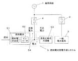
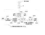
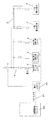
図1はこの発明の燃料電池発電冷凍システムの一実施形態を含む電力系統を示すブロック図である。 FIG. 1 is a block diagram showing an electric power system including an embodiment of a fuel cell power generation refrigeration system of the present invention.
この電力系統は、商用系統1に対して、一般動力盤2を介して一般電力負荷3を接続しているとともに、冷凍空調動力盤4を介して燃料電池発電冷凍システム5を接続している。
This power system is connected to a commercial system 1 with a
前記一般動力盤2、冷凍空調動力盤4は従来公知であるから、説明を省略する。
The
前記一般電力負荷3は、ビル、店舗などに設置されている電力負荷のうち、冷凍機、空調機を除く負荷であり、エレベータや電灯、パソコンなどが例示できる。
The
前記燃料電池発電冷凍システム5は、従来公知の燃料の供給を受けて発電を行う電池本体51と、電池本体51からの出力電力を入力として交流電力に変換するインバータ52と、インバータ52から出力される交流電力を動作電力として受け取る蒸気圧縮式冷凍機53とを有している。なお、この蒸気圧縮式冷凍機53はインバータ52の出力電力、または商用系統電力により駆動されるモータを駆動源とするものである。そして、この蒸気圧縮式冷凍機53は、例えば、空調機の冷媒駆動源として機能するものである。また、前記インバータ52と蒸気圧縮式冷凍機53とを接続する接続ラインの途中部54を冷凍空調動力盤4に接続している。
The fuel cell power
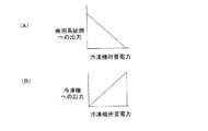
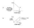
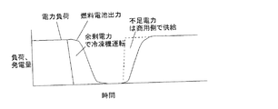
図2は商用系統側への電力出力{図2中(A)参照}、および蒸気圧縮式冷凍機53への電力出力{図2中(B)参照}を説明する図である。 FIG. 2 is a diagram for explaining the power output to the commercial system side {see (A) in FIG. 2] and the power output to the vapor compression refrigerator 53 (see (B) in FIG. 2).
図2から分かるように、蒸気圧縮式冷凍機53の所要電力が減少すると、蒸気圧縮式冷凍機53への電力出力が減少し、商用系統1側への電力出力が増加する。
As can be seen from FIG. 2, when the required power of the
したがって、燃料電池の発電電力を、年間を通じ有効に利用できるとともに、発電装置用の電源盤と空調用の動力盤とを兼用することができるので設置スペース、機器、工事コストを低減でき、経済性、省エネ性に優れた燃料電池発電冷凍システムを構成することができる。 Therefore, the power generated by the fuel cell can be used effectively throughout the year, and the power panel for the power generator and the power panel for air conditioning can be used together. A fuel cell power generation refrigeration system having excellent energy saving performance can be configured.
図3は燃料電池発電冷凍システム5の他の構成を示すブロック図である。
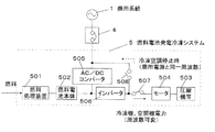
この燃料電池発電冷凍システム5は、外部から供給される燃料を処理する燃料処理装置501と、処理された燃料を入力とする燃料電池本体502と、圧縮機等503と、圧縮機等の駆動源であるモータ504と、商用系統1に対して冷凍空調動力盤4を介して接続されるAC/DCコンバータ505と、燃料電池本体502の出力、AC/DCコンバータ505の出力を入力とするインバータ506と、インバータ506の出力をモータ504に供給する第1スイッチ507と、インバータ506の出力を冷凍空調動力盤4に供給する第2スイッチ508とを有している。
FIG. 3 is a block diagram showing another configuration of the fuel cell power
The fuel cell power
この場合には、商用系統と圧縮機駆動用電動機との間の電力変換と、燃料電池と圧縮機駆動用電動機との間の電力変換とに、同じインバータを共用しているので、設置スペース、機器、工事コストを低減できるとともに、インバータの変換ロスを少なくすることができ、経済性、省エネ性を一層向上させることができる。 In this case, since the same inverter is shared for power conversion between the commercial system and the compressor driving motor and power conversion between the fuel cell and the compressor driving motor, the installation space, Equipment and construction costs can be reduced, conversion loss of the inverter can be reduced, and economic efficiency and energy saving can be further improved.
図4は燃料電池発電冷凍システム5のさらに他の構成を示すブロック図である。
FIG. 4 is a block diagram showing still another configuration of the fuel cell power generation /
この燃料電池発電冷凍システム5は、圧縮機等503、モータ504、AC/DCコンバータ505、インバータ506、第1スイッチ507、および第2スイッチ508を2系統分並列に設けた点が図3の燃料電池発電冷凍システム5と異なるだけである。
This fuel cell power
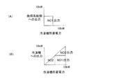
この場合には、蒸気圧縮式冷凍機の必要運転負荷に応じて、圧縮機の運転台数を制御するともに、運転していない圧縮機系統のインバータから商用系統側に燃料電池の発電電力を供給することができる{図5中(A)(B)参照}。また、部分負荷運転時にも商用系統側に燃料電池の発電電力を供給することができる。 In this case, the number of operating compressors is controlled according to the required operating load of the vapor compression refrigerator, and the generated power of the fuel cell is supplied from the inverter of the compressor system that is not in operation to the commercial system side. {See (A) and (B) in FIG. 5}. Moreover, the power generated by the fuel cell can be supplied to the commercial system side even during partial load operation.
図6は燃料電池発電冷凍システム5のさらに他の構成を示すブロック図である。
この燃料電池発電冷凍システム5は、AC/DCコンバータ505に代えて双方向AC/DCインバータ505’を採用した点、第1スイッチ507を省略した点、および第2スイッチ508を含む電力経路を省略した点が図3の燃料電池発電冷凍システム5と異なるだけである。
FIG. 6 is a block diagram showing still another configuration of the fuel cell power generation /
In this fuel cell power
この場合には、簡単な構成で冷凍機側への電力供給と商用系統側への電力供給とを分離することができ、冷凍機の運転周波数に影響されずに、燃料電池の余剰発電電力を商用系統側に供給することができる。 In this case, the power supply to the refrigerator side and the power supply to the commercial system side can be separated with a simple configuration, and the surplus generated power of the fuel cell can be generated without being affected by the operating frequency of the refrigerator. It can be supplied to the commercial system.
図7は燃料電池発電冷凍システム5のさらに他の構成を示すブロック図である。
FIG. 7 is a block diagram showing still another configuration of the fuel cell power generation /
この燃料電池発電冷凍システム5は、双方向AC/DCインバータ505’を経由することなく冷凍空調動力盤4に接続されるモータ504、およびこのモータ504を駆動源とする圧縮機等503をさらに含む点が図6の燃料電池発電冷凍システム5と異なるだけである。
This fuel cell power
この場合には、インバータの容量を低減できるとともに、コスト、装置容積を低減することができる。 In this case, the capacity of the inverter can be reduced, and the cost and the device volume can be reduced.
また、燃料電池の容量を蒸気圧縮式冷凍機の圧縮機駆動用電動機に動作用電力を供給するインバータの容量よりも大きく設定していれば、燃料電池が最大容量で運転中であることに応答して双方向AC/DCインバータ505’を介して商用系統側に発電電力を供給することができ、蒸気圧縮式冷凍機の最大容量運転時にも商用系統1側へ電力を供給することができる{図8中(A)(B)参照}。
If the capacity of the fuel cell is set larger than the capacity of the inverter that supplies operating power to the compressor driving motor of the vapor compression refrigeration machine, it responds that the fuel cell is operating at the maximum capacity. Thus, the generated power can be supplied to the commercial system side via the bidirectional AC /
図9は燃料電池発電冷凍システム5のさらに他の構成を示すブロック図である。
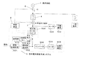
この燃料電池発電冷凍システム5は、一般動力盤2、冷凍空調動力盤4と商用系統1との間に電力量検知部6を接続した点、冷凍空調動力盤4と双方向AC/DCインバータ505’との間に発電出力検知部7を接続した点、および電力量検知部6からの出力、発電出力検知部7からの出力を入力として、燃料処理装置501、インバータ506、および双方向AC/DCインバータ505’に対する制御信号を出力する制御装置8を設けた点が図7の燃料電池発電冷凍システム5と異なるだけである。
FIG. 9 is a block diagram showing still another configuration of the fuel cell power generation /
This fuel cell power
前記電力量検知部6としては、実際に電力量を検知するものであってもよいが、電力量に対応する値として電流値を検知するものであってもよい。
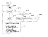
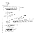
図10は図9の燃料電池発電冷凍システム5の作用を説明するフローチャートであり、ステップSP1において、商用系統1側から流入する電流値ICを検知し、ステップSP2において、電流値ICが第1の閾値ICLよりも小さいか否かを判定し、電流値ICが第1の閾値ICLよりも小さくない場合には、ステップSP3において、電流値ICが第2の閾値ICHよりも小さいか否かを判定する。
The power
FIG. 10 is a flowchart for explaining the operation of the fuel cell power generation /
そして、電流値ICが第1の閾値ICLよりも小さい場合には、ステップSP4において、燃料電池発電冷凍システム発電出力制御目標値WSを0に設定する。
電流値ICが第1の閾値ICLと第2の閾値ICHとの間の値である場合には、ステップSP5において、燃料電池発電冷凍システム発電出力制御目標値WSをWR×(IC−ICL)/(ICH−ICL)に設定する。なお、WRは燃料電池定格出力である。
If the current value IC is smaller than the first threshold value ICL, the fuel cell power generation / refrigeration system power generation output control target value WS is set to 0 in step SP4.
When the current value IC is a value between the first threshold value ICL and the second threshold value ICH, in step SP5, the fuel cell power generation refrigeration system power generation output control target value WS is set to WR × (IC−ICL) / Set to (ICH-ICL). Note that WR is a fuel cell rated output.
電流値ICが第2の閾値ICH以上である場合には、ステップSP6において、燃料電池発電冷凍システム発電出力制御目標値WSをWRに設定する。 If the current value IC is greater than or equal to the second threshold value ICH, in step SP6, the fuel cell power generation / refrigeration system power generation output control target value WS is set to WR.
ステップSP4の処理、ステップSP5の処理、またはステップSP6の処理が行われた場合には、ステップSP7において、発電出力Wを燃料電池発電冷凍システム発電出力制御目標値WSと等しくするように燃料電池容量制御(例えば、双方向AC/DCインバータ505’のAC出力制御、および燃料処理装置501での燃料、空気供給量制御)を行う。ただし、インバータ506の出力は、例えば、空調要求により従来公知のように制御される。
When the process of step SP4, the process of step SP5, or the process of step SP6 is performed, in step SP7, the fuel cell capacity is set so that the power generation output W is equal to the fuel cell power generation refrigeration system power generation output control target value WS. Control (for example, AC output control of the bidirectional AC /
ステップSP7の処理が行われた後は、再びステップSP1の処理を行う。
制御に用いる閾値は、
例えば閾値ICLは、燃料電池定格出力の30%に相当する電流値、
閾値ICHは、燃料電池定格出力に相当する電流値、
というように定める。
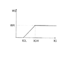
このようにすれば図11に示すように、電流値ICに応じて燃料電池発電冷凍システム発電出力制御目標値WSを設定することができる。
After the process of step SP7 is performed, the process of step SP1 is performed again.
The threshold used for control is
For example, the threshold value ICL is a current value corresponding to 30% of the rated output of the fuel cell,
The threshold value ICH is a current value corresponding to the fuel cell rated output,
It is determined as follows.
In this way, as shown in FIG. 11, the fuel cell power generation refrigeration system power generation output control target value WS can be set according to the current value IC.
この場合には、燃料電池の容量制御を適切に行うことができ、系統電力への逆潮流などを防止することができる。 In this case, the capacity control of the fuel cell can be appropriately performed, and a reverse power flow to the system power can be prevented.
図12は燃料電池発電冷凍システム5のさらに他の構成を示すブロック図である。
FIG. 12 is a block diagram showing still another configuration of the fuel cell power generation /
この燃料電池発電冷凍システム5は、制御装置8によって制御される充放電リレー509を介して蓄電部510を燃料電池本体502に接続した点が図7の燃料電池発電冷凍システム5と異なるだけである。
This fuel cell power generation /
前記蓄電部510としては、二次電池、キャパシターなどが例示できる。
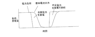
この場合には、一般負荷の負荷変動が早く、燃料電池の運転容量が追従しないような場合に、蓄電部510に対して充放電することによって、負荷の消費電力と燃料電池の発電量とのアンバランスを吸収することができる(図13参照)。
また、検知された電力供給量が、逆潮流の可能性がある程度に減少したことを検出し、この検出に応答して、燃料電池が負荷に追従するまで蒸気圧縮式冷凍機を駆動源とする機器の運転容量を強制的に増加させるように構成してもよく(図14参照)、蓄電部510がなくても負荷に対する追従遅れを防止することができ、蓄電部510がある場合には、蓄電部510の容量を低減することができる。
Examples of the
In this case, when the load fluctuation of the general load is fast and the operating capacity of the fuel cell does not follow, the
Further, the detected power supply amount detects that the possibility of reverse power flow has decreased to some extent, and in response to this detection, the vapor compression refrigerator is used as a drive source until the fuel cell follows the load. It may be configured to forcibly increase the operating capacity of the device (see FIG. 14), and the follow-up delay with respect to the load can be prevented without the
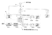
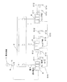
図15はこの発明の燃料電池発電冷凍システムの一実施形態を含む電力系統を概略的に示すブロック図である。 FIG. 15 is a block diagram schematically showing an electric power system including an embodiment of the fuel cell power generation refrigeration system of the present invention.
この電力系統は、商用系統1に対して、電力量検知部6を介して、さらに複数の冷凍空調動力盤4の各々を介して燃料電池発電冷凍システム5を接続している。ただし、図15には、制御装置8と、空調機の室外部分511および室内機512と、空調機リモコン513、514と、制御装置8間を接続する燃料電池制御用連絡配線515とが示されているだけであるが、上記の実施形態で説明された他の構成要素を含んでいることはもちろんである。
This power system is connected to the commercial system 1 through a power
また、前記制御装置8は、1つが親機であり、残余が子機である。
図16は親機の処理を説明するフローチャートである。
ステップSP1において、商用系統1側から流入する電流値ICを検知し、ステップSP2において、電流値ICが第1の閾値ICLよりも小さいか否かを判定し、電流値ICが第1の閾値ICLよりも小さくない場合には、ステップSP3において、電流値ICが第2の閾値ICHよりも小さいか否かを判定する。
そして、電流値ICが第1の閾値ICLよりも小さい場合には、ステップSP4において、燃料電池発電出力制御目標値WSを0に設定する。
電流値ICが第1の閾値ICLと第2の閾値ICHとの間の値である場合には、ステップSP5において、燃料電池発電出力制御目標値WSをWR×(IC−ICL)/(ICH−ICL)に設定する。なお、WRは燃料電池定格出力である。
Further, one of the
FIG. 16 is a flowchart for explaining the processing of the master unit.
In step SP1, the current value IC flowing from the commercial system 1 side is detected, and in step SP2, it is determined whether or not the current value IC is smaller than the first threshold value ICL, and the current value IC is the first threshold value ICL. If not, it is determined in step SP3 whether or not the current value IC is smaller than the second threshold value ICH.
If the current value IC is smaller than the first threshold value ICL, the fuel cell power generation output control target value WS is set to 0 in step SP4.
When the current value IC is a value between the first threshold value ICL and the second threshold value ICH, in step SP5, the fuel cell power generation output control target value WS is set to WR × (IC−ICL) / (ICH− ICL). Note that WR is a fuel cell rated output.
電流値ICが第2の閾値ICH以上である場合には、ステップSP6において、燃料電池発電出力制御目標値WSをWRに設定する。 If the current value IC is greater than or equal to the second threshold value ICH, in step SP6, the fuel cell power generation output control target value WS is set to WR.
ステップSP4の処理、ステップSP5の処理、またはステップSP6の処理が行われた場合には、ステップSP7において、ΣWSiがWSとなるように目標発電出力WSiを算出し(例えば、WSi=WS/nの演算を行って目標発電出力WSiを算出し)、ステップSP8において、各子機に目標発電出力WSiを送信し、ステップSP9において、発電出力が目標発電出力WS1となるように燃料電池の容量を制御する。 When the process of step SP4, the process of step SP5, or the process of step SP6 is performed, in step SP7, the target power generation output WSi is calculated so that ΣWSi becomes WS (for example, WSi = WS / n In step SP8, the target power generation output WSi is transmitted to each slave unit, and in step SP9, the capacity of the fuel cell is controlled so that the power generation output becomes the target power generation output WS1. To do.
なお、nは制御装置8の数を表す。
ステップSP9の処理が行われた後は、再びステップSP1の処理を行う。
図17は子機の処理を説明するフローチャートである。
ステップSP1において、親機から目標発電出力WSiを受信し、ステップSP2において、発電出力が目標発電出力WSiとなるように燃料電池の容量を制御する。
Note that n represents the number of
After the process of step SP9 is performed, the process of step SP1 is performed again.
FIG. 17 is a flowchart for explaining processing of the slave unit.
In step SP1, the target power generation output WSi is received from the parent device, and in step SP2, the capacity of the fuel cell is controlled so that the power generation output becomes the target power generation output WSi.
ステップSP2の処理が行われた後は、再びステップSP1の処理を行う。
ただし、空調機側の制御は、燃料電池とは独立に、空調機リモコンからの運転設定に基づいて行うようにしている。もちろん、空調機に代えて他の用途の冷凍機を採用することができる。
After the process of step SP2 is performed, the process of step SP1 is performed again.
However, the control on the air conditioner side is performed based on the operation setting from the air conditioner remote controller independently of the fuel cell. Of course, a refrigerator for other purposes can be employed instead of the air conditioner.
この場合には、空調負荷(冷凍負荷)にきめ細かく追従できるとともに、一般負荷が小さい場合でも、台数制御により負荷追従性を向上させることができ、しかも、電源供給の信頼性を高めることができる。 In this case, it is possible to closely follow the air conditioning load (refrigeration load), and even when the general load is small, the load followability can be improved by controlling the number of units, and the reliability of power supply can be improved.
図18はこの発明の燃料電池発電冷凍システムの一実施形態を含む電力系統を概略的に示すブロック図である。 FIG. 18 is a block diagram schematically showing an electric power system including an embodiment of the fuel cell power generation / refrigeration system of the present invention.
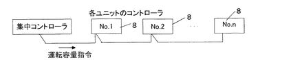
図18においては、集中コントローラ80を有し、この集中コントローラ80から、各制御装置8に運転容量指令を供給するようにしている。すなわち、親機と子機との区分を排除している。
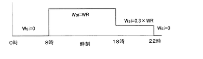
この場合には、スケジュール運転(例えば、図19参照)や、合計発電容量制御等を効率的に行うことができる。
In FIG. 18, a
In this case, schedule operation (see, for example, FIG. 19), total power generation capacity control, and the like can be performed efficiently.
図20はこの発明の燃料電池発電冷凍システムの一実施形態を含む電力系統を概略的に示すブロック図である。 FIG. 20 is a block diagram schematically showing an electric power system including one embodiment of the fuel cell power generation / refrigeration system of the present invention.
図20においては、この電力系統は、商用系統1に対して、冷凍空調動力盤4を介して燃料電池発電冷凍システム5を接続している。そして、商用系統1に対して、一般動力盤2を介して一般電力負荷3を接続している。また、電力量検知部6からの出力を入力として所定の処理を行い、運転指令を複数の燃料電池発電冷凍システム5に供給する集中コントローラ80を設けている。そして、この集中コントローラ80は、インターネットなどの通信網81を介して遠隔監視コンピュータ82に接続されている。
In FIG. 20, this power system is connected to a commercial system 1 with a fuel cell power
この場合には、集中コントローラ80に情報を集中することで、適切な運転制御を行うことができる
また、前記集中コントローラ80が、少なくとも電力料金と燃料料金とを出力する料金出力部と、この料金に応答して、燃料電池の運転の制御、および出力電力の分配の制御を行う制御部とをさらに含むことが好ましく、季節別、時間別などのきめ細かい優先出力制御(どの出力を優先するかの制御)を行うことができ、ランニングメリットを極大化することができる。
前記料金出力部は、料金を算出して出力するものであってもよく、料金を記憶しておいて必要なものを出力するものであってもよい。
In this case, it is possible to perform appropriate operation control by concentrating information on the
The fee output unit may calculate and output a fee, or may store a fee and output a necessary one.
しかし、前記料金出力部は、料金算出のための単価データおよび料金算出ソフトウエアが遠隔監視コンピュータ82から書き換え可能であることが好ましく、顧客がこれらのデータ、ソフトウエアを入力する手間が省け、更新忘れなどによる不利益を未然に防止することができる。
However, it is preferable that the charge output unit can rewrite the unit price data and the charge calculation software for calculating the charge from the
図21は集中コントローラ80における発電量制御処理の一例を説明するフローチャートである。
FIG. 21 is a flowchart for explaining an example of the power generation amount control process in the
ステップSP1において、エネルギー料金単価に基づいて目標発電出力WSoを算出し、ステップSP2において、商用系統1側から流入する電流値ICを検知し、ステップSP3において、電流値ICが第1の閾値ICLよりも小さいか否かを判定し、電流値ICが第1の閾値ICLよりも小さくない場合には、ステップSP4において、電流値ICが第2の閾値ICHよりも小さいか否かを判定する。 In step SP1, the target power generation output WSo is calculated based on the energy rate unit price. In step SP2, the current value IC flowing from the commercial system 1 side is detected. In step SP3, the current value IC is greater than the first threshold value ICL. If the current value IC is not smaller than the first threshold value ICL, it is determined in step SP4 whether the current value IC is smaller than the second threshold value ICH.
そして、電流値ICが第1の閾値ICLよりも小さい場合には、ステップSP5において、燃料電池発電出力制御目標値WSを0に設定する。
電流値ICが第1の閾値ICLと第2の閾値ICHとの間の値である場合には、ステップSP6において、燃料電池発電出力制御目標値WSをWSo×(IC−ICL)/(ICH−ICL)に設定する。なお、WRは燃料電池定格出力である。
If the current value IC is smaller than the first threshold value ICL, the fuel cell power generation output control target value WS is set to 0 in step SP5.
When the current value IC is a value between the first threshold value ICL and the second threshold value ICH, in step SP6, the fuel cell power generation output control target value WS is set to WSo × (IC−ICL) / (ICH− ICL). Note that WR is a fuel cell rated output.
電流値ICが第2の閾値ICH以上である場合には、ステップSP7において、燃料電池発電出力制御目標値WSをWSoに設定する。
ステップSP5の処理、ステップSP6の処理、またはステップSP7の処理が行われた場合には、ステップSP8において、ΣWSiがWSとなるように目標発電出力WSiを算出し(例えば、WSi=WS/nの演算を行って目標発電出力WSiを算出し)、ステップSP9において、各燃料電池発電冷凍システム5に目標発電出力WSiを送信する。
If the current value IC is equal to or greater than the second threshold value ICH, in step SP7, the fuel cell power generation output control target value WS is set to WSo.
When the processing of step SP5, the processing of step SP6, or the processing of step SP7 is performed, in step SP8, the target power generation output WSi is calculated so that ΣWSi becomes WS (for example, WSi = WS / n The target power generation output WSi is calculated by calculation), and in step SP9, the target power generation output WSi is transmitted to each fuel cell power
ステップSP9の処理が行われた後は、再びステップSP1の処理を行う。
前記ステップSP1における処理は、例えば、次のように行われる。
先ず、電気料金CE[円/kWh]の算出を次のように行う。
夏季(7/1〜9/30)、平日13時〜16時ならCE=15.9
夏季(7/1〜9/30)、平日8時〜13時、16時〜22時ならCE=14.7
その他(10/1〜6/30)、平日8時〜22時ならCE=13.65
22時〜8時、または休日ならCE=6.05
また、ガス料金CG[円/kWh]の算出を次のように行う。
CG=4
また、メンテナンス費用CM[円/kWh]の算出を次のように行う。
CM=2
また、発電効率E[−]の算出を行う。
E=0.45
これらに基づいて目標発電出力WSo[kW]の算出を次のように行う。
CG/E+CM<CEの場合には、WSo=WR
CG/E+CM≧CEの場合には、WSo=0
図22は各燃料電池発電冷凍システム5の処理を説明するフローチャートである。
After the process of step SP9 is performed, the process of step SP1 is performed again.
The process in step SP1 is performed as follows, for example.
First, the electricity rate CE [yen / kWh] is calculated as follows.
In summer (7 / 1-9 / 30), weekdays from 13:00 to 16:00 CE = 15.9
In summer (7 / 1-9 / 30),
Others (10/1-6/30), CE = 13.65 if weekdays are 8: 00-22: 00
From 22:00 to 8:00 or on holidays, CE = 6.05
Further, the calculation of the gas charge CG [yen / kWh] is performed as follows.
CG = 4
The maintenance cost CM [yen / kWh] is calculated as follows.
CM = 2
Further, the power generation efficiency E [−] is calculated.
E = 0.45
Based on these, the target power generation output WSo [kW] is calculated as follows.
If CG / E + CM <CE, WSo = WR
If CG / E + CM ≧ CE, WSo = 0
FIG. 22 is a flowchart for explaining processing of each fuel cell power generation /
ステップSP1において、集中コントローラ80から目標発電出力WSiを受信し、ステップSP2において、発電出力が目標発電出力WSiとなるように燃料電池の容量を制御する。
In step SP1, the target power generation output WSi is received from the
ステップSP2の処理が行われた後は、再びステップSP1の処理を行う。
ただし、空調機側の制御は、燃料電池とは独立に、空調機リモコンからの運転設定に基づいて行うようにしている。もちろん、空調機に代えて他の用途の冷凍機を採用することができる。
After the process of step SP2 is performed, the process of step SP1 is performed again.
However, the control on the air conditioner side is performed based on the operation setting from the air conditioner remote controller independently of the fuel cell. Of course, a refrigerator for other purposes can be employed instead of the air conditioner.
以上の各実施形態において、前記蒸気圧縮式冷凍機は、直膨サイクルを利用するものであることが好ましく、直膨サイクルの冷凍機を負荷系統毎に分散配置することで、負荷への追従性や個別運転停止を容易にすることができ、ひいては、利便性と省エネ性とを高めることができる。 In each of the embodiments described above, the vapor compression refrigerator is preferably one that uses a direct expansion cycle, and the direct expansion cycle refrigerator is dispersedly arranged for each load system, thereby being able to follow the load. In addition, it is possible to easily stop the individual operation, and as a result, it is possible to improve convenience and energy saving.
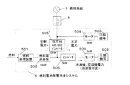
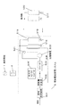
図23はこの発明の燃料電池発電冷凍システムのさらに他の実施形態を示す概略ブロック図である。 FIG. 23 is a schematic block diagram showing still another embodiment of the fuel cell power generation / refrigeration system of the present invention.
この燃料電池発電冷凍システム5は、従来公知のように、モータを駆動源とする圧縮機503により冷媒ガスを圧縮し、凝縮器520で凝縮させ、膨張弁518で減圧ののち蒸発器519で冷媒を蒸発させる冷媒回路を持ち、しかも冷媒の流れを反転させる四方弁521を設けて、冷房動作、または暖房動作を行わせるようにしている。
In this fuel cell power
図23は暖房運転を示し、蒸発器519は室外熱交換器、凝縮器520は室内熱交換器である。冷房運転時には四方弁521が切り替わり、室外熱交換器が凝縮器、室内熱交換器は蒸発器となる。冷房運転では冷媒は各室内用に設けられた膨張弁517で減圧される。
そして、燃料電池本体502からの排熱と冷媒との間で熱交換を行わせる排熱利用熱交換器516を設けている。
この場合には、排熱を同じシステム内で利用することで、適切に利用することができ、ひいては、省エネ性を高めることができる。
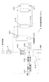
図24はこの発明の燃料電池発電冷凍システムのさらに他の実施形態を示す概略ブロック図である。
この燃料電池発電冷凍システム5は、排熱利用熱交換器516として、燃料電池本体502からの排熱と水との間で熱交換を行わせ、給湯を行うものを採用した点が図23の燃料電池発電冷凍システム5と異なるだけである。
ただし、給湯を行うものに限定されるのではなく、熱を利用する種々の機器に適用可能である。
この場合には、冷凍機と比較してエネルギー利用効率が低い機器等に排熱を優先的に利用して省エネ性を高めることができる。
FIG. 23 shows the heating operation, in which the
An exhaust heat
In this case, by using exhaust heat in the same system, it can be used appropriately, and as a result, energy saving can be improved.
FIG. 24 is a schematic block diagram showing still another embodiment of the fuel cell power generation / refrigeration system of the present invention.
The fuel cell power
However, the present invention is not limited to the one that supplies hot water, but can be applied to various devices that use heat.
In this case, it is possible to enhance energy saving by preferentially using the exhaust heat for a device having low energy use efficiency as compared with the refrigerator.
1 商用系統
5 燃料電池発電冷凍システム
51 燃料電池本体
52 インバータ
53 蒸気圧縮式冷凍機
80 集中コントローラ
501 燃料処理装置
502 燃料電池本体
503 圧縮機等
504 モータ
505 AC/DCコンバータ
505' 双方向AC/DCインバータ
510 蓄電部
DESCRIPTION OF SYMBOLS 1
Claims (16)
蒸気圧縮式冷凍機(53)に対して、商用系統(1)の電源を入力として動作用電力を供給する動力盤(4)と、
燃料電池(51)と、
蒸気圧縮式冷凍機(53)の圧縮機駆動用電動機に対して、燃料電池(51)の出力を入力として所定の電力変換を行って動作用電力を供給する電力変換手段(52)と、
蒸気圧縮式冷凍機(53)の圧縮機駆動用電動機の駆動用電力を、燃料電池(51)によって発電された電力によって賄うとともに、蒸気圧縮式冷凍機(53)の総所要電力が燃料電池(51)の発電能力を下回ること、冷凍機(53)が停止していることに対応して、燃料電池(51)によって発電された電力を商用系統(1)側に動力盤(4)を介して供給する電力供給制御手段と
を含むことを特徴とする燃料電池発電冷凍システム。 A vapor compression refrigerator (53);
A power panel (4) for supplying operation power to the vapor compression refrigerator (53) with the power supply of the commercial system (1) as an input;
A fuel cell (51);
A power conversion means (52) for supplying power for operation by performing predetermined power conversion with the output of the fuel cell (51) as an input to the compressor driving motor of the vapor compression refrigerator (53);
The electric power for driving the compressor driving motor of the vapor compression refrigerator (53) is provided by the electric power generated by the fuel cell (51), and the total electric power required for the vapor compression refrigerator (53) is the fuel cell ( 51) The power generated by the fuel cell (51) is sent to the commercial system (1) via the power panel (4) in response to the power generation capacity of the fuel cell (51) being reduced. And a power supply control means for supplying the fuel cell.
Priority Applications (6)
| Application Number | Priority Date | Filing Date | Title |
|---|---|---|---|
| JP2004106584A JP5002883B2 (en) | 2004-03-31 | 2004-03-31 | Fuel cell power generation refrigeration system |
| CNB2005800105820A CN100508263C (en) | 2004-03-31 | 2005-03-10 | Fuel Cell Power Generation Refrigeration System |
| US10/594,601 US7614245B2 (en) | 2004-03-31 | 2005-03-10 | Fuel cell power generation refrigerating system |
| PCT/JP2005/004182 WO2005099006A1 (en) | 2004-03-31 | 2005-03-10 | Fuel cell power generating refrigeration system |
| EP05720453A EP1750319B1 (en) | 2004-03-31 | 2005-03-10 | Fuel cell power generating refrigeration system |
| AT05720453T ATE555511T1 (en) | 2004-03-31 | 2005-03-10 | FUEL CELL POWER GENERATION COOLING SYSTEM |
Applications Claiming Priority (1)
| Application Number | Priority Date | Filing Date | Title |
|---|---|---|---|
| JP2004106584A JP5002883B2 (en) | 2004-03-31 | 2004-03-31 | Fuel cell power generation refrigeration system |
Publications (2)
| Publication Number | Publication Date |
|---|---|
| JP2005293997A true JP2005293997A (en) | 2005-10-20 |
| JP5002883B2 JP5002883B2 (en) | 2012-08-15 |
Family
ID=35125386
Family Applications (1)
| Application Number | Title | Priority Date | Filing Date |
|---|---|---|---|
| JP2004106584A Expired - Fee Related JP5002883B2 (en) | 2004-03-31 | 2004-03-31 | Fuel cell power generation refrigeration system |
Country Status (6)
| Country | Link |
|---|---|
| US (1) | US7614245B2 (en) |
| EP (1) | EP1750319B1 (en) |
| JP (1) | JP5002883B2 (en) |
| CN (1) | CN100508263C (en) |
| AT (1) | ATE555511T1 (en) |
| WO (1) | WO2005099006A1 (en) |
Cited By (8)
| Publication number | Priority date | Publication date | Assignee | Title |
|---|---|---|---|---|
| JP2007271114A (en) * | 2006-03-30 | 2007-10-18 | Osaka Gas Co Ltd | Air conditioning and power generation system |
| JP2009043525A (en) * | 2007-08-08 | 2009-02-26 | Panasonic Corp | Fuel cell power generator |
| US7602073B2 (en) * | 2002-11-15 | 2009-10-13 | Sprint Communications Company L.P. | Power system with fuel cell and localized air-conditioning for computing equipment |
| JP2010040305A (en) * | 2008-08-05 | 2010-02-18 | Panasonic Corp | Fuel cell power generating device |
| JP2018007335A (en) * | 2016-06-28 | 2018-01-11 | 京セラ株式会社 | Power generating system and control method therefor |
| JP2020145769A (en) * | 2019-03-04 | 2020-09-10 | 東京瓦斯株式会社 | Heat pump system |
| JP2021164317A (en) * | 2020-03-31 | 2021-10-11 | 大和ハウス工業株式会社 | Power supply system |
| CN114488821A (en) * | 2022-04-06 | 2022-05-13 | 国网浙江省电力有限公司电力科学研究院 | Method and system for prediction control of interval economic model of fuel cell oxygen ratio |
Families Citing this family (14)
| Publication number | Priority date | Publication date | Assignee | Title |
|---|---|---|---|---|
| KR20080083538A (en) * | 2007-03-12 | 2008-09-18 | 삼성전자주식회사 | Fuel cell system and air conditioner using same |
| CA2711382A1 (en) * | 2008-01-03 | 2009-07-16 | Idle Free Systems, Llc | Charge circuit systems and methods of using the same |
| US20110030399A1 (en) * | 2008-01-08 | 2011-02-10 | Carrier Corporation | Refrigerant system with fuel cell for electricity generation |
| US20100114384A1 (en) * | 2008-10-28 | 2010-05-06 | Trak International, Llc | Controls for high-efficiency heat pumps |
| US9543884B2 (en) * | 2009-06-10 | 2017-01-10 | Lg Electronics Inc. | Motor control device of air conditioner using distributed power supply |
| CN102136778A (en) * | 2010-01-22 | 2011-07-27 | 能原科技股份有限公司 | Generator-heat pump composite device |
| US20140018015A1 (en) | 2012-03-21 | 2014-01-16 | Robertshaw Controls Company | Methods and systems for preserving the power source life of a wireless end node prior to deployment in a transport refrigeration system |
| CN103953985A (en) * | 2014-04-16 | 2014-07-30 | 沈阳时尚实业有限公司 | Household air conditioning system with fuel cell |
| US10442297B2 (en) | 2017-05-24 | 2019-10-15 | Toyota Motor Engineering & Manufacturing North America, Inc. | Fuel cell vehicle with power modules |
| US10518652B2 (en) | 2017-05-24 | 2019-12-31 | Toyota Motor Engineering & Manufacturing North America, Inc. | Fuel cell vehicle with power modules |
| US10793157B2 (en) | 2017-05-24 | 2020-10-06 | Toyota Motor Engineering & Manufacturing North America, Inc. | Operating electrified vehicles during traction events |
| EP4341109A4 (en) | 2021-05-17 | 2024-06-19 | H2CS Hydro Cool Systems Limited | CARBON-FREE EMISSION AND HIGHLY EFFICIENT INTELLIGENT HYDROGEN POWERED COOLING SYSTEM FOR TRANSPORTATION PURPOSES |
| CN113948737A (en) * | 2021-09-01 | 2022-01-18 | 深圳市燃气集团股份有限公司 | High-efficiency refrigerating system of high-temperature fuel cell |
| EP4361526A1 (en) | 2022-10-28 | 2024-05-01 | Carrier Corporation | Refrigeration system |
Citations (7)
| Publication number | Priority date | Publication date | Assignee | Title |
|---|---|---|---|---|
| JPH0240461Y2 (en) * | 1984-10-23 | 1990-10-29 | ||
| JPH06274233A (en) * | 1993-03-24 | 1994-09-30 | Sanyo Electric Co Ltd | Power system |
| JP2001201138A (en) * | 2000-01-21 | 2001-07-27 | Mitsubishi Electric Corp | Air conditioner |
| JP2001231176A (en) * | 2000-02-18 | 2001-08-24 | Toshiba Corp | Fuel cell power supply |
| JP2002198079A (en) * | 2000-12-27 | 2002-07-12 | Matsushita Electric Ind Co Ltd | Control device for fuel cell system |
| JP2003077507A (en) * | 2001-08-30 | 2003-03-14 | Sanyo Electric Co Ltd | Fuel cell power generating system |
| JP2003130491A (en) * | 2001-10-18 | 2003-05-08 | Toshiba International Fuel Cells Corp | Fuel cell exhaust heat utilizing air conditioning system |
Family Cites Families (12)
| Publication number | Priority date | Publication date | Assignee | Title |
|---|---|---|---|---|
| US4377074A (en) * | 1981-06-29 | 1983-03-22 | Kaman Sciences Corporation | Economizer refrigeration cycle space heating and cooling system and process |
| US5678410A (en) * | 1993-08-06 | 1997-10-21 | Toyota Jidosha Kabushiki Kaisha | Combined system of fuel cell and air-conditioning apparatus |
| JPH085190A (en) | 1994-06-17 | 1996-01-12 | Mitsubishi Heavy Ind Ltd | Fuel battery-driven air conditioner |
| DE19739917A1 (en) * | 1997-09-11 | 1999-03-18 | Siemens Ag | System for supplying electromotive consumers with electrical energy |
| US6253563B1 (en) * | 1999-06-03 | 2001-07-03 | The United States Of America As Represented By The Administrator Of The National Aeronautics And Space Administration | Solar-powered refrigeration system |
| US6755041B2 (en) * | 2001-07-26 | 2004-06-29 | Carrier Corporation | Electrically powered trailer refrigeration unit |
| ITVA20010041A1 (en) * | 2001-11-16 | 2003-05-16 | Chemieco Srl | SYSTEM OF ACCUMULATION AND / OR TRANSFORMATION OF ENERGY FROM SOURCES TO VOLTAGE AND FREQUENCY CHANGING |
| JP3810307B2 (en) * | 2001-11-27 | 2006-08-16 | 大阪瓦斯株式会社 | Power supply |
| US7040430B2 (en) * | 2002-02-21 | 2006-05-09 | Matsushita Electric Industrial Co., Ltd. | Cogeneration vehicle system utilizing a fuel cell car and a mobile unit as a component of the system |
| JP2003262409A (en) * | 2002-03-06 | 2003-09-19 | Daikin Ind Ltd | Refrigeration equipment and refrigeration system |
| DE10233821A1 (en) | 2002-07-25 | 2004-02-05 | Daimlerchrysler Ag | Controlling energy supply of mobile device with electric drive motor(s) and hybrid energy supply system involves deriving difference between fuel cell system and storage battery power components |
| JP3825020B2 (en) * | 2002-08-01 | 2006-09-20 | 株式会社アイ・ヒッツ研究所 | Distributed power supply system |
-
2004
- 2004-03-31 JP JP2004106584A patent/JP5002883B2/en not_active Expired - Fee Related
-
2005
- 2005-03-10 EP EP05720453A patent/EP1750319B1/en not_active Expired - Lifetime
- 2005-03-10 CN CNB2005800105820A patent/CN100508263C/en not_active Expired - Fee Related
- 2005-03-10 AT AT05720453T patent/ATE555511T1/en active
- 2005-03-10 US US10/594,601 patent/US7614245B2/en not_active Expired - Fee Related
- 2005-03-10 WO PCT/JP2005/004182 patent/WO2005099006A1/en not_active Ceased
Patent Citations (7)
| Publication number | Priority date | Publication date | Assignee | Title |
|---|---|---|---|---|
| JPH0240461Y2 (en) * | 1984-10-23 | 1990-10-29 | ||
| JPH06274233A (en) * | 1993-03-24 | 1994-09-30 | Sanyo Electric Co Ltd | Power system |
| JP2001201138A (en) * | 2000-01-21 | 2001-07-27 | Mitsubishi Electric Corp | Air conditioner |
| JP2001231176A (en) * | 2000-02-18 | 2001-08-24 | Toshiba Corp | Fuel cell power supply |
| JP2002198079A (en) * | 2000-12-27 | 2002-07-12 | Matsushita Electric Ind Co Ltd | Control device for fuel cell system |
| JP2003077507A (en) * | 2001-08-30 | 2003-03-14 | Sanyo Electric Co Ltd | Fuel cell power generating system |
| JP2003130491A (en) * | 2001-10-18 | 2003-05-08 | Toshiba International Fuel Cells Corp | Fuel cell exhaust heat utilizing air conditioning system |
Cited By (10)
| Publication number | Priority date | Publication date | Assignee | Title |
|---|---|---|---|---|
| US7602073B2 (en) * | 2002-11-15 | 2009-10-13 | Sprint Communications Company L.P. | Power system with fuel cell and localized air-conditioning for computing equipment |
| JP2007271114A (en) * | 2006-03-30 | 2007-10-18 | Osaka Gas Co Ltd | Air conditioning and power generation system |
| JP2009043525A (en) * | 2007-08-08 | 2009-02-26 | Panasonic Corp | Fuel cell power generator |
| JP2010040305A (en) * | 2008-08-05 | 2010-02-18 | Panasonic Corp | Fuel cell power generating device |
| JP2018007335A (en) * | 2016-06-28 | 2018-01-11 | 京セラ株式会社 | Power generating system and control method therefor |
| JP2020145769A (en) * | 2019-03-04 | 2020-09-10 | 東京瓦斯株式会社 | Heat pump system |
| JP7181127B2 (en) | 2019-03-04 | 2022-11-30 | 東京瓦斯株式会社 | heat pump system |
| JP2021164317A (en) * | 2020-03-31 | 2021-10-11 | 大和ハウス工業株式会社 | Power supply system |
| JP7438826B2 (en) | 2020-03-31 | 2024-02-27 | 大和ハウス工業株式会社 | power supply system |
| CN114488821A (en) * | 2022-04-06 | 2022-05-13 | 国网浙江省电力有限公司电力科学研究院 | Method and system for prediction control of interval economic model of fuel cell oxygen ratio |
Also Published As
| Publication number | Publication date |
|---|---|
| CN100508263C (en) | 2009-07-01 |
| ATE555511T1 (en) | 2012-05-15 |
| WO2005099006A1 (en) | 2005-10-20 |
| JP5002883B2 (en) | 2012-08-15 |
| EP1750319B1 (en) | 2012-04-25 |
| CN1938886A (en) | 2007-03-28 |
| US20070193289A1 (en) | 2007-08-23 |
| US7614245B2 (en) | 2009-11-10 |
| EP1750319A1 (en) | 2007-02-07 |
| EP1750319A4 (en) | 2009-07-01 |
Similar Documents
| Publication | Publication Date | Title |
|---|---|---|
| JP5002883B2 (en) | Fuel cell power generation refrigeration system | |
| CN101135512A (en) | Air-conditioning and electric power generating system and control method for the same | |
| JP6930844B2 (en) | Compressed air storage power generator | |
| CN105318494A (en) | Air conditioner and method for controlling same | |
| JP2011217590A (en) | Air conditioning system | |
| EP1890094A2 (en) | Cogeneration system | |
| JP2008107000A (en) | Air conditioning / power generation apparatus and control method thereof | |
| CN119289501B (en) | Efficient and energy-saving intelligent building temperature control management method and system | |
| CN105180342A (en) | Air Conditioner And Method For Controlling Same | |
| JP3417365B2 (en) | Electric storage equipment | |
| CN120402992A (en) | Self-powered air conditioning system including a thermal storage device | |
| JP2005293998A (en) | Fuel cell power generation refrigeration system | |
| CN218296018U (en) | Air condensing units and air conditioner | |
| KR102436313B1 (en) | High Efficiency Heating and Cooling System Using Self-Generating Means | |
| JP2002106911A (en) | Air conditioner and its control system | |
| EP3511637A1 (en) | Power-source-system-integrating air-conditioning device | |
| JP2005295674A (en) | Power supply | |
| JP2009240084A (en) | Power-generating and air-conditioning system | |
| JP2000320866A (en) | Air conditioner | |
| CN120969949A (en) | Integrated cold and heat source system | |
| CN115289550B (en) | Air conditioner outdoor unit, air conditioner and control method thereof | |
| KR20190119834A (en) | Air conditioner | |
| JP2004125258A (en) | Gas heat pump type air conditioner | |
| WO2020053986A1 (en) | Air conditioning system | |
| KR101435086B1 (en) | Multi-type air conditioner and operating method for the same |
Legal Events
| Date | Code | Title | Description |
|---|---|---|---|
| RD03 | Notification of appointment of power of attorney |
Free format text: JAPANESE INTERMEDIATE CODE: A7423 Effective date: 20061030 |
|
| A621 | Written request for application examination |
Free format text: JAPANESE INTERMEDIATE CODE: A621 Effective date: 20070329 |
|
| RD04 | Notification of resignation of power of attorney |
Free format text: JAPANESE INTERMEDIATE CODE: A7424 Effective date: 20091019 |
|
| A131 | Notification of reasons for refusal |
Free format text: JAPANESE INTERMEDIATE CODE: A131 Effective date: 20101109 |
|
| A521 | Request for written amendment filed |
Free format text: JAPANESE INTERMEDIATE CODE: A523 Effective date: 20110107 |
|
| A131 | Notification of reasons for refusal |
Free format text: JAPANESE INTERMEDIATE CODE: A131 Effective date: 20111108 |
|
| A521 | Request for written amendment filed |
Free format text: JAPANESE INTERMEDIATE CODE: A523 Effective date: 20111221 |
|
| TRDD | Decision of grant or rejection written | ||
| A01 | Written decision to grant a patent or to grant a registration (utility model) |
Free format text: JAPANESE INTERMEDIATE CODE: A01 Effective date: 20120424 |
|
| A01 | Written decision to grant a patent or to grant a registration (utility model) |
Free format text: JAPANESE INTERMEDIATE CODE: A01 |
|
| A61 | First payment of annual fees (during grant procedure) |
Free format text: JAPANESE INTERMEDIATE CODE: A61 Effective date: 20120507 |
|
| FPAY | Renewal fee payment (event date is renewal date of database) |
Free format text: PAYMENT UNTIL: 20150601 Year of fee payment: 3 |
|
| R151 | Written notification of patent or utility model registration |
Ref document number: 5002883 Country of ref document: JP Free format text: JAPANESE INTERMEDIATE CODE: R151 |
|
| FPAY | Renewal fee payment (event date is renewal date of database) |
Free format text: PAYMENT UNTIL: 20150601 Year of fee payment: 3 |
|
| LAPS | Cancellation because of no payment of annual fees |