JP2005294001A - Photoelectric conversion element - Google Patents
Photoelectric conversion element Download PDFInfo
- Publication number
- JP2005294001A JP2005294001A JP2004106616A JP2004106616A JP2005294001A JP 2005294001 A JP2005294001 A JP 2005294001A JP 2004106616 A JP2004106616 A JP 2004106616A JP 2004106616 A JP2004106616 A JP 2004106616A JP 2005294001 A JP2005294001 A JP 2005294001A
- Authority
- JP
- Japan
- Prior art keywords
- working electrode
- photoelectric conversion
- conversion element
- dye
- electrode
- Prior art date
- Legal status (The legal status is an assumption and is not a legal conclusion. Google has not performed a legal analysis and makes no representation as to the accuracy of the status listed.)
- Granted
Links
Images
Classifications
-
- Y—GENERAL TAGGING OF NEW TECHNOLOGICAL DEVELOPMENTS; GENERAL TAGGING OF CROSS-SECTIONAL TECHNOLOGIES SPANNING OVER SEVERAL SECTIONS OF THE IPC; TECHNICAL SUBJECTS COVERED BY FORMER USPC CROSS-REFERENCE ART COLLECTIONS [XRACs] AND DIGESTS
- Y02—TECHNOLOGIES OR APPLICATIONS FOR MITIGATION OR ADAPTATION AGAINST CLIMATE CHANGE
- Y02E—REDUCTION OF GREENHOUSE GAS [GHG] EMISSIONS, RELATED TO ENERGY GENERATION, TRANSMISSION OR DISTRIBUTION
- Y02E10/00—Energy generation through renewable energy sources
- Y02E10/50—Photovoltaic [PV] energy
- Y02E10/542—Dye sensitized solar cells
Landscapes
- Hybrid Cells (AREA)
- Photovoltaic Devices (AREA)
Abstract
【課題】 発電効率に優れ、不具合発生時に修理や交換が容易な光電変換素子を提供する。
【解決手段】 作用極14、対極18および電解質層15とからなる積層体25と、作用極14または対極18に形成された導電体20と、これらを収容する筐体30とを備えた色素増感型太陽電池10において、筐体30は、積層体25を覆う枠体31と、積層体25を枠体31に固定する蓋体32とからなり、枠体31は作用極18において導電体20が形成されている位置に対応した領域を覆うものとする。
【選択図】 図1PROBLEM TO BE SOLVED: To provide a photoelectric conversion element which is excellent in power generation efficiency and can be easily repaired or replaced when a failure occurs.
SOLUTION: A dye sensitizer comprising a laminate 25 composed of a working electrode 14, a counter electrode 18 and an electrolyte layer 15, a conductor 20 formed on the working electrode 14 or the counter electrode 18, and a casing 30 for housing them. In the sensitive solar cell 10, the casing 30 includes a frame body 31 that covers the stacked body 25 and a lid body 32 that fixes the stacked body 25 to the frame body 31, and the frame body 31 is the conductor 20 at the working electrode 18. An area corresponding to the position where the is formed is covered.
[Selection] Figure 1
Description
本発明は、色素増感太陽電池などの光電変換素子に関する。 The present invention relates to a photoelectric conversion element such as a dye-sensitized solar cell.
環境問題、資源問題などを背景に、クリーンエネルギーとしての太陽電池が注目を集めている。太陽電池としては単結晶、多結晶あるいはアモルファスのシリコンを用いたものがある。しかしながら、従来のシリコン系太陽電池は、製造コストが高い上に、原料供給が不充分であるなどの課題が残されているため、普及していない。
また、Cu−In−Se系(CIS系とも呼ぶ)などの化合物系太陽電池も開発されており、この化合物系太陽電池は極めて高い光電変換効率を示すなど優れた特徴を有している。しかしながら、この化合物系太陽電池も、コストや環境負荷などの問題から普及していない。
Against the backdrop of environmental problems and resource problems, solar cells as clean energy are attracting attention. Some solar cells use single crystal, polycrystalline or amorphous silicon. However, conventional silicon-based solar cells are not widely used because of problems such as high production costs and insufficient supply of raw materials.
In addition, a compound solar cell such as a Cu-In-Se system (also referred to as a CIS system) has been developed, and this compound solar cell has excellent characteristics such as extremely high photoelectric conversion efficiency. However, this compound solar cell is not popular due to problems such as cost and environmental load.
これらの太陽電池に対して、スイスのグレッツェルらのグループなどから提案された色素増感型太陽電池は、安価で、かつ、高い光電変換効率が得られる光電変換素子として注目されている。 In contrast to these solar cells, dye-sensitized solar cells proposed by the group of Gretzel et al. In Switzerland are attracting attention as photoelectric conversion elements that are inexpensive and can provide high photoelectric conversion efficiency.
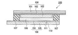
図4は、従来の色素増感型太陽電池の一例を示す概略断面図である。
この色素増感型太陽電池100は、増感色素を担持させた多孔質半導体電極(以下、「色素増感半導体電極」と言うこともある。)103が一方の面に形成された第一基板101と、導電膜104が形成された第二基板105と、これらの間に封入されたゲル状電解質などからなる電解質層106とから概略構成されている。
FIG. 4 is a schematic cross-sectional view showing an example of a conventional dye-sensitized solar cell.
This dye-sensitized
第一基板101としては光透過性の板材が用いられ、第一基板101の色素増感半導体電極103と接する面には導電性を付与するために透明導電膜102が設けられている。また、第一基板101、透明導電膜102および色素増感半導体電極103から窓極108が構成されている。
A light transmissive plate material is used as the
一方、第二基板105としては、電解質層106と接する側の面には導電性を付与するために炭素や白金などからなる導電膜104が設けられている。また、第二基板105および導電膜104から対極109が構成されている。
On the other hand, as the
色素増感型太陽電池100では、色素増感半導体電極103と導電膜104が対向するように、第一基板101と第二基板105が所定の間隔をおいて配置されており、両基板間の周縁部に熱可塑性樹脂からなる封止材107が設けられている。この封止材107は、電解質層106に含まれる電解液が漏出したり、揮発性成分が揮発したりすることを防ぐ役目を果たしている。
In the dye-sensitized
次に、色素増感型太陽電池100の製造方法の概略を説明する。
まず、熱可塑性樹脂からなる封止材107を介して窓極108と対極109を積層した後、窓極108および対極109、または、窓極108あるいは対極109のいずれか一方を介して封止材107を加熱して、溶融することにより、窓極108と対極109を接着して、一対の電極(窓極108と対極109)からなる積層体を組み立てる。
次いで、対極109を貫通するように設けられた注入口110を通して、窓極108と対極109の間にヨウ素・ヨウ化物イオンなどの酸化・還元種を含む電解液を充填した後、注入口110を蓋111で塞ぎ、電荷移送用の電解質層106を形成し、一対の電極(窓極108と対極109)と、これらの間に挟まれた電解質層106からなる色素増感型太陽電池100を得る(例えば、特許文献1、非特許文献1参照。)。
Next, an outline of a method for manufacturing the dye-sensitized
First, after laminating the
Next, an electrolytic solution containing oxidation / reduction species such as iodine / iodide ions is filled between the
上述のような色素増感型太陽電池100の製造では、積層体を組み立てる際に封止材107を溶融する熱によって、色素増感半導体電極103に担持させた増感色素が劣化するおそれがある。また、積層体を組み立てた後に、窓極108と対極109の間に電解液を充填しなければならなかった。その結果、電解液の粘度が高いと、電解液の充填には多大な時間と手間を要するという問題があった。
In the production of the dye-sensitized
また、封止材107は熱可塑性樹脂からなるので、耐候性に劣るため、長期使用には適さないという問題があった。
さらに、窓極108と対極109の間に電解液を充填するためには、これらの電極間には所定の距離が必要である。その結果、最終的に得られる色素増感型太陽電池100の発電効率が低下するという問題があった。
Furthermore, in order to fill the electrolyte solution between the
本発明は、前記事情に鑑みてなされたもので、安価に製造することが可能で、長期信頼性および発電効率に優れ、不具合発生時に修理や交換が容易な光電変換素子を提供することを目的とする。 The present invention has been made in view of the above circumstances, and an object thereof is to provide a photoelectric conversion element that can be manufactured at low cost, has excellent long-term reliability and power generation efficiency, and can be easily repaired or replaced when a failure occurs. And
本発明は、上記課題を解決するために、作用極、対極およびこれらの間に形成された電解質層を備える積層体と、前記作用極に形成された導電体と、これらを収容する筐体とを備えた光電変換素子であって、前記筐体は、前記積層体を覆う枠体と、前記積層体を前記枠体に固定する蓋体とからなり、前記枠体は前記作用極において前記導電体が形成されている位置に対応した領域を覆う光電変換素子を提供する。 In order to solve the above problems, the present invention provides a laminate including a working electrode, a counter electrode, and an electrolyte layer formed therebetween, a conductor formed on the working electrode, and a housing for housing them. The housing includes a frame that covers the stacked body and a lid that fixes the stacked body to the frame, and the frame is electrically conductive at the working electrode. Provided is a photoelectric conversion element that covers a region corresponding to a position where a body is formed.
上記光電変換素子において、前記導電体が前記作用極の周縁部に設けられていることが好ましい。 In the photoelectric conversion element, it is preferable that the conductor is provided on a peripheral edge of the working electrode.
上記光電変換素子において、前記蓋体が前記枠体に取り外し可能に固定されていることが好ましい。 In the photoelectric conversion element, it is preferable that the lid body is detachably fixed to the frame body.
上記光電変換素子において、前記対極と前記蓋体との間に弾性部材が介在していることが好ましい。 In the photoelectric conversion element, an elastic member is preferably interposed between the counter electrode and the lid.
本発明の光電変換素子は、積層体を組み立てた後に、作用極と対極の間に電解液を充填する必要がないので、工程を簡略化することができる。また、本発明の光電変換素子は、熱可塑性樹脂などからなる封止材を必要としないので、耐候性すなわち長期信頼性に優れている。さらに、本発明の光電変換素子は、作用極と対極の間に距離をおく必要がないので、発電効率に優れている。また、本発明の光電変換素子は、筐体を構成する枠体に設けられた押圧部が、作用極における少なくとも導電体が形成されている領域を覆っており、作用極における発電に関与する部分が蓋板などで覆われることなく、電解質層を作用極と対極で挟んでなる積層体が筐体によって封止されているから、作用極における発電に関与する部分に入射する光量が減少することがないため、より発電効率に優れたものとなる。 Since the photoelectric conversion element of the present invention does not need to be filled with an electrolytic solution between the working electrode and the counter electrode after the stacked body is assembled, the process can be simplified. Moreover, since the photoelectric conversion element of this invention does not require the sealing material which consists of thermoplastic resins etc., it is excellent in a weather resistance, ie, long-term reliability. Furthermore, since the photoelectric conversion element of the present invention does not require a distance between the working electrode and the counter electrode, it has excellent power generation efficiency. Further, in the photoelectric conversion element of the present invention, the pressing portion provided on the frame constituting the casing covers at least the region where the conductor is formed in the working electrode, and is a part involved in power generation in the working electrode. Is not covered with a cover plate, etc., and the laminated body with the electrolyte layer sandwiched between the working electrode and the counter electrode is sealed by the housing, so that the amount of light incident on the portion of the working electrode involved in power generation is reduced. Therefore, the power generation efficiency is further improved.
また、本発明の光電変換素子において、導電体を作用極の周縁部に形成すれば、作用極における発電に関与する部分の面積を大きくすることができ、基板の抵抗を下げることができるため、より発電効率に優れた光電変換素子を実現することができる。 Further, in the photoelectric conversion element of the present invention, if the conductor is formed on the peripheral portion of the working electrode, the area of the portion involved in power generation in the working electrode can be increased, and the resistance of the substrate can be reduced. A photoelectric conversion element with more excellent power generation efficiency can be realized.
また、本発明の光電変換素子において、筐体を構成する枠体と蓋体を取り外し可能に固定すれば、積層体に不具合が生じた場合、これを筐体から取り外して修理したり、良品に交換したりすることができる。また、筐体を繰り返し使用することができるので、製造コストを削減することもできる。 In addition, in the photoelectric conversion element of the present invention, if the frame and the lid constituting the casing are detachably fixed, if a failure occurs in the laminated body, this can be removed from the casing for repair, Can be exchanged. Further, since the housing can be used repeatedly, the manufacturing cost can be reduced.
さらに、本発明の光電変換素子において、対極と蓋体との間に弾性部材を介在させれば、積層体の積層方向に外力が加えられても、作用極と対極との間で横ズレが発生するのを抑制することができる。また、弾性部材によって、積層体を、その積層方向に柔軟性を保ちながら強固に筐体に固定することができる。 Furthermore, in the photoelectric conversion element of the present invention, if an elastic member is interposed between the counter electrode and the lid, even if an external force is applied in the stacking direction of the stacked body, there is a lateral shift between the working electrode and the counter electrode. Generation | occurrence | production can be suppressed. Further, the laminated body can be firmly fixed to the casing while maintaining flexibility in the laminating direction by the elastic member.
以下、本発明を実施した光電変換素子について、図面を参照して説明する。 Hereinafter, a photoelectric conversion element embodying the present invention will be described with reference to the drawings.
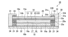
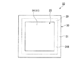
図1は、本発明に係る光電変換素子の第一の実施形態として、色素増感型太陽電池を示す概略断面図である。図2は、図1の色素増感型太陽電池を示す概略平面図である。
図1および図2中、符号10は色素増感型太陽電池、11は第一の基板、12は透明導電膜、13は多孔質酸化物半導体層、14は作用極、15は電解質層、16は第二の基板、17は導電膜、18は対極、19は弾性部材、20は導電体、21は隙間充填材、25は積層体、30は筐体、31は枠体、32は蓋体、33は接着剤層、34は接着剤層をそれぞれ示している。
FIG. 1 is a schematic cross-sectional view showing a dye-sensitized solar cell as a first embodiment of a photoelectric conversion element according to the present invention. FIG. 2 is a schematic plan view showing the dye-sensitized solar cell of FIG.
1 and 2,
この色素増感型太陽電池10は、増感色素が表面に担持された多孔質酸化物半導体層13が一方の面14aに設けられた作用極14と、一方の面14aと対向して配置された対極18と、一方の面14aと対極18における一方の面14aと対向する面18a(以下、「対極18の一方の面18a」と称する。)との間に形成された電解質層15と、一方の面14aの周縁部に設けられた導電体20と、これらを収容する筐体30とから概略構成されている。
In this dye-sensitized
なお、この色素増感太陽電池10では、電解質層15をなす電解質の大部分が、多孔質酸化物半導体層13の空隙部分に含浸された状態となっている。
In the dye-sensitized
作用極14は、第一の基板11と、この一方の面11a上に順に形成された透明導電膜12および多孔質酸化物半導体層13とから構成されている。また、作用極14の一方の面14aにおける周縁部には、多孔質酸化物半導体層13の側面13aを囲むように導電体20が設けられている。
The working
対極18は、第二の基板16と、この一方の面16a上に形成された導電膜17とから構成されている。
The
色素増感型太陽電池10において、電解質層15を作用極14と対極18で挟んでなる積層体25が光電変換素子として機能する。
In the dye-sensitized
色素増感型太陽電池10において、積層体25は、積層体25の側面25aおよび作用極14における他方の面14bの一部を覆う枠体31と、対極18の他方の面18bに接して積層体25を枠体31に固定する蓋体32とからなる筐体30内に収容されている。
In the dye-sensitized
枠体31は、積層体25の側面25aの全域を外側から覆う枠部31Aと、枠部31Aから、これと垂直かつ内方(中心方向)に突設された押圧部31Bとから構成されている。そして、枠部31Aの内面31aには積層体25の側面25aが接するか、または、枠部31Aの内面31aの近傍に積層体25の側面25aが配されるように、積層体25が筐体30内に収容されている。また、押圧部31Bの内面31bには、接着剤層33を介して作用極14の他方の面14bが接している。また、押圧部31Bは、作用極14の他方の面14bにおいて、その一方の面14aに形成されている導電体20の位置に対応した領域を覆うように設けられており、押圧部31Bの端面31cと、導電体20の多孔質酸化物半導体層13側の側面20aとがほぼ同一面上に存在している。
また、蓋体32は、弾性部材19を介して対極18の他方の面18bに接している。さらに、蓋体32は、接着剤層34を介して枠体31に固定されている。
The
The
なお、押圧部31Bが、作用極14の他方の面14bにおいて、その一方の面14aに形成されている導電体20の位置に対応した領域を覆うように設けられている構造は、図1に示すように、押圧部31Bの端面31cと、導電体20の多孔質酸化物半導体層13側の側面20aとがほぼ同一面上に存在している構造だけでなく、押圧部31Bの端面31cが多孔質酸化物半導体層13の存在する領域に存在する構造や、押圧部31Bの端面31cが導電体20の側面20aよりも枠部31A側の領域に存在する構造を含む。
The structure in which the
また、蓋体32と導電体20との間には、弾性部材19を介し、かつ、対極18の側面を囲むように隙間充填材21が配されている。なお、本発明の光電変換素子にあっては、隙間充填材は設けられていなくてもよい。
Further, a
このような構成とすることにより、積層体25は、その上下面が枠体31の押圧部31Bと蓋体32で挟み込まれて、その積層方向に押圧された状態で、筐体30内に収容される。また、この状態で、積層体25の側面25aの全域が枠部31Aに覆われて、積層体25は筐体30によって一括して封止されている。
By adopting such a configuration, the
なお、蓋体32は、接着剤層34を介して枠体31に固定されているが、枠体31と蓋体32との間に、剃刀の刃などの薄く、硬い刃物を挿入することにより、蓋体32は、枠体31から容易に取り外すことができるようになっていることが好ましい。
The
第一の基板11としては、光透過性の素材からなる基板が用いられ、ガラス、ポリエチレンテレフタレート、ポリエチレンナフタレート、ポリカーボネート、ポリエーテルスルホンなど、通常、太陽電池の透明基板として用いられるものであればいかなるものもでも用いることができる。第一の基板11は、これらの中から電解液への耐性などを考慮して適宜選択されるが、用途上、できる限り光透過性に優れる基板が好ましい。
As the
透明導電膜12は、第一の基板11に導電性を付与するために、その一方の面11aに形成された金属、炭素、導電性金属酸化物などからなる薄膜である。
透明導電膜12として金属薄膜や炭素薄膜を形成する場合、第一の基板11の透明性を著しく損なわない構造とする。透明導電膜12を形成する導電性金属酸化物としては、例えば、インジウム−スズ酸化物(Indium−Tin Oxide、ITO)、酸化スズ(SnO2)、フッ素ドープの酸化スズなどが用いられる。
The transparent
In the case where a metal thin film or a carbon thin film is formed as the transparent
多孔質酸化物半導体層13は、透明導電膜12の上に設けられており、その表面には増感色素が担持されている。多孔質酸化物半導体層13を形成する半導体としては特に限定されず、通常、太陽電池用の多孔質半導体を形成するのに用いられるものであればいかなるものでも用いることができる。このような半導体としては、例えば、酸化チタン(TiO2)、酸化スズ(SnO2)、酸化タングステン(WO3)、酸化亜鉛(ZnO)、酸化ニオブ(Nb2O5)などを用いることができる。
多孔質酸化物半導体層13を形成する方法としては、例えば、ゾルゲル法からの膜形成、微粒子の泳動電着、発泡剤による多孔質化、ポリマービーズなどとの混合物塗布後における余剰成分の除去などの方法が挙げられるが、これらに限定されるものではない。
The porous
Examples of the method for forming the porous
増感色素としては、ビピリジン構造、ターピリジン構造などを配位子に含むルテニウム錯体、ポルフィリン、フタロシアニンなどの含金属錯体、エオシン、ローダミン、メロシアニンなどの有機色素などを適用することができ、これらの中から、用途、使用半導体に適した励起挙動を示すものを特に限定無く選ぶことができる。 As the sensitizing dye, a ruthenium complex containing a bipyridine structure or a terpyridine structure as a ligand, a metal-containing complex such as porphyrin or phthalocyanine, or an organic dye such as eosin, rhodamine or merocyanine can be applied. Therefore, those exhibiting excitation behavior suitable for the application and the semiconductor used can be selected without particular limitation.
電解質層15は、多孔質酸化物半導体層13内に電解液を含浸させてなるものか、または、多孔質酸化物半導体層13内に電解液を含浸させた後に、この電解液を適当なゲル化剤を用いてゲル化(擬固体化)して、多孔質酸化物半導体層13と一体に形成されてなるものが用いられる。
The
電解液としては、ヨウ素、ヨウ化物イオン、ターシャリーブチルピリジンなどの電解質成分が、エチレンカーボネートやメトキシアセトニトリルなどの有機溶媒に溶解されてなるものが用いられる。 As the electrolytic solution, an electrolytic solution in which an electrolyte component such as iodine, iodide ion, or tertiary butyl pyridine is dissolved in an organic solvent such as ethylene carbonate or methoxyacetonitrile is used.
電解液をゲル化する際に用いられるゲル化剤としては、ポリフッ化ビニリデン、ポリエチレンオキシド誘導体、アミノ酸誘導体などが挙げられる。 Examples of the gelling agent used when gelling the electrolytic solution include polyvinylidene fluoride, polyethylene oxide derivatives, amino acid derivatives, and the like.
第二の基板16としては、第一の基板11と同様のものや、特に光透過性をもつ必要がないことから金属板、合成樹脂板などが用いられる。
As the
導電膜17は、第二の基板16に導電性を付与するために、その一方の面16aに形成された白金などの金属、炭素などからなる薄膜である。導電膜17としては、例えば炭素や白金などの層を、蒸着、スパッタ、塩化白金酸塗布後に熱処理を行ったものが好適に用いられるが、電極として機能するものであれば特に限定されるものではない。
The
弾性部材19としては、発泡ポリエチレン、発泡ポリウレタン、ゴムスポンジなどが用いられる。
色素増感型太陽電池10では、積層体25を筐体30によって封止することにより、積層体25にはその積層方向に外力が加えられる。弾性部材19を対極18と蓋体32との間に介在させることにより、この外力によって、作用極14と対極18との間で横ズレが発生するのを抑制することができる。また、弾性部材19によって、積層体25を、その積層方向に柔軟性を保ちながら強固に筐体30に固定することができる。
As the
In the dye-sensitized
導電体20としては、スクリーン印刷法により、銀などの導電性インクで回路形成したものや、はんだ付けをして回路形成したものなどが挙げられる。導電体20は、色素増感型太陽電池10内で発生した電子を効率良く収集するために、作用極14の周縁部に(多孔質酸化物半導体層13の側面を囲むように)設けられている。
また、この導電体20を介して、積層体25と筐体30に設けられた外部接続用端子(図示略)とが電気的に接続できるようになっている。
Examples of the
In addition, the laminate 25 and an external connection terminal (not shown) provided in the
隙間充填材21としては、発泡ポリエチレン、発泡ポリウレタン、ゴムスポンジなどが用いられる。
蓋体32と導電体20との間に隙間充填材21を介在させることにより、積層体25を筐体30によって封止する際に生じる外力によって、作用極14と対極18との間で横ズレが発生するのを抑制することができる。また、隙間充填材21によって、積層体25を、その積層方向に柔軟性を保ちながら強固に筐体30に固定することができる。
As the
By interposing the
筐体30を構成する枠体31および蓋体32を形成する素材としては特に限定されないが、各種金属、セラミックス、各種合成樹脂などが用いられる。
Although it does not specifically limit as a raw material which forms the
接着剤層33をなす接着剤としては、第一の基板11を枠体31に接着可能なものであればいかなるものでも用いることができるが、特に、所定の外力を加えることによって、積層体25を枠体31から容易に取り外すことができるものが好ましい。接着剤層33をなす接着剤としては、例えば、エポキシ系接着剤などが用いられる。
Any adhesive can be used as the adhesive forming the
接着剤層34をなす接着剤としては、接着剤層33をなす接着剤と同様のものを用いることも可能であるが、蓋体32を枠体31に接着可能なものであればいかなるものでも用いることができる。特に、接着剤層34をなす接着剤としては、所定の外力を加えることによって、蓋体32を枠体31から容易に取り外すことができるものが好ましい。接着剤層34をなす接着剤としては、例えば、エポキシ系接着剤などが用いられる。
As the adhesive forming the
以上説明したように、色素増感型太陽電池10では、積層体20を組み立てた後に、作用極14と対極18の間に電解液を充填する必要がないので、工程を簡略化することができる。また、色素増感型太陽電池10は、熱可塑性樹脂などからなる封止材を必要としないので、耐候性すなわち長期信頼性に優れている。さらに、色素増感型太陽電池10は、作用極14と対極18の間に距離をおく必要がないので、発電効率に優れている。
また、色素増感型太陽電池10は、筐体30を構成する枠体31に設けられた押圧部31Bが、作用極14の他方の面14bにおいて、一方の面14aに形成されている導電体20の存する領域を覆っており、作用極14における発電に関与する部分が蓋板などで覆われることなく、積層体25が筐体30によって封止される。したがって、作用極14における発電に関与する部分に入射する光量が減少することがないため、色素増感型太陽電池10はより発電効率に優れたものとなる。
As described above, in the dye-sensitized
Further, in the dye-sensitized
また、色素増感型太陽電池10では、導電体20が作用極14における一方の面14aの周縁部に形成されているから、作用極14における発電に関与する部分の面積を大きくすることができるため、色素増感型太陽電池10はより発電効率に優れたものとなる。
Further, in the dye-sensitized
さらに、色素増感型太陽電池10では、積層体25が接着剤層33を介して枠体31に取り外し可能に固定され、かつ、蓋体32が接着剤層34を介して枠体31に取り外し可能に固定されているから、積層体25に不具合が生じた場合、これを筐体30から取り外して修理したり、良品に交換したりすることができる。また、筐体30を繰り返し使用することができるので、製造コストを削減することもできる。
Further, in the dye-sensitized
次に、本発明に係る光電変換素子の製造方法の一実施形態を、図1を参照して説明する。
この実施形態では、まず、第一の基板11における一方の面11a上に透明導電膜12および多孔質酸化物半導体層13が所定の方法により順に形成されてなる作用極14を用意する。
Next, an embodiment of a method for producing a photoelectric conversion element according to the present invention will be described with reference to FIG.
In this embodiment, first, a working
次いで、作用極14の一方の面14aにおける周縁部に導電体20を設ける。
Next, the
次いで、多孔質酸化物半導体層13に、予めゲル化剤が添加された電解液を滴下して含浸させた後、この電解液をゲル化させて、多孔質酸化物半導体層13と一体をなす電解質層15を形成する。
Next, the porous
次いで、作用極14の他方の面14bが接着剤層33を介して枠体31の押圧部31Bの内面31bに接するように、枠体31内に作用極14を配置する。
Next, the working
次いで、導電膜17が電解質層15に重なるように、対極18を作用極13に重ねて、電解質層15を作用極14と対極18で挟んでなる積層体25を、枠体31内に形成する。
Next, the
次いで、対極18の側面を囲み、導電体20に当接するように隙間充填材21を配する。
次いで、弾性部材19を介して対極18を覆うように蓋体32を配する。
Next, the
Next, the
次いで、蓋体32の外側から積層体25の積層方向に荷重を加えながら、蓋体32を、接着剤層34を介して枠体31に固定し、筐体30で積層体25を封止することにより、色素増感型太陽電池10を得る。
Next, the
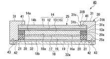
図3は、本発明に係る光電変換素子の第二の実施形態として、色素増感型太陽電池を示す概略断面図である。
この実施形態では、上記第一の実施形態とは、筐体30によって積層体25を封止する構造が異なっている。図3において、図1に示した第一の実施形態の構成要素と同じ構成要素には同一符号を付して、その説明を省略する。
FIG. 3 is a schematic cross-sectional view showing a dye-sensitized solar cell as a second embodiment of the photoelectric conversion element according to the present invention.
In this embodiment, the structure which seals the
色素増感型太陽電池40において、枠部31Aの内面31aには積層体25の側面25aが接しており、また、押圧部31Bの内面31bには、封止部材41を介して作用極14の他方の面14bが接している。
また、蓋体32は、封止部材42を介して枠体31に接している。さらに、蓋体32は、螺子43によって枠体31に固定されている。
In the dye-sensitized
Further, the
なお、筐体30による積層体25の封止を十分なものとするためには、封止部材41を嵌合するための溝などからなる嵌合部(図示略)を、枠体31の押圧部31Bの内面31bおよび作用極14の一方の面14aに設けることが好ましい。また、封止部材42を嵌合するための溝などからなる嵌合部(図示略)を、枠体31の枠部31Aにおける蓋体32と接触する面および蓋体32の枠部31Aと接触する面に設けることが好ましい。
In order to sufficiently seal the
封止部材41、42としては、ニトリルゴム、シリコンゴム、ウレタンゴム、フッ素ゴムなどの弾性材料や、ポリ四フッ化エチレンなどからなるOリング、ガスケットなどが用いられる。
As the sealing
螺子43としては、蓋体32を枠体31に接合、固定することができるものであればいかなるものでも用いることができる。
Any
なお、この実施形態では、蓋体32を枠体31に接合、固定する手段として、螺子43を例示したが、本発明の光電変換素子はこれに限定されない。本発明の光電変換素子にあっては、蓋体を枠体に接合、固定する手段としては、例えば、枠体に設けられた被係止部に、蓋体に回転可能に設けられたフラップ状の係止部を係止する手段や、枠体の枠部、押圧部および蓋体の表面に接するように筐体の外側に装着される、断面コ字形スリーブ状のバネのクランプ力によって挟み込む手段などを用いることもできる。また、前記被係止部に係止部を係止する手段は、被嵌合部に嵌合部を嵌合する手段であってもよい。
In this embodiment, the
このような構成とすることにより、積層体25に不具合が生じた場合、積層体25を筐体30から容易に取り外して修理したり、良品に交換したりすることができる。
By adopting such a configuration, when a failure occurs in the stacked
本発明によれば、高粘度もしくはゲル状の電解質を容易に充填できる利点を保ちながら、発生した電子を効率良く収集することができる色素増感型太陽電池を実現することができる。また、セルに入射する光量を減少することなく、筐体との分離性も高いことから、保守性やリサイクル性も高く、環境負荷の低い太陽電池を実現することができる。 According to the present invention, it is possible to realize a dye-sensitized solar cell that can efficiently collect generated electrons while maintaining the advantage of easily filling a high-viscosity or gel electrolyte. Further, since the separation from the housing is high without reducing the amount of light incident on the cell, a solar cell with high maintainability and recyclability and low environmental load can be realized.
10,40・・・色素増感型太陽電池、11・・・第一の基板、12・・・透明導電膜、13・・・多孔質酸化物半導体層、14・・・作用極、15・・・電解質層、16・・・第二の基板、17・・・導電膜、18・・・対極、19・・・弾性部材、20・・・導電体、21・・・隙間充填材、25・・・積層体、30・・・筐体、31・・・枠体、31A・・・枠部、31B・・・押圧部、32・・・蓋体、33,34・・・接着剤層、41,42・・・封止部材、43・・・螺子。
DESCRIPTION OF
Claims (4)
前記筐体は、前記積層体を覆う枠体と、前記積層体を前記枠体に固定する蓋体とからなり、前記枠体は前記作用極において前記導電体が形成されている位置に対応した領域を覆うことを特徴とする光電変換素子。 A photoelectric conversion element comprising a working electrode, a counter electrode and a laminate including an electrolyte layer formed therebetween, a conductor formed on the working electrode, and a housing for housing them,
The housing includes a frame body that covers the laminated body and a lid body that fixes the laminated body to the frame body, and the frame body corresponds to a position where the conductor is formed on the working electrode. A photoelectric conversion element covering an area.
The photoelectric conversion element according to claim 1, wherein an elastic member is interposed between the counter electrode and the lid.
Priority Applications (10)
| Application Number | Priority Date | Filing Date | Title |
|---|---|---|---|
| JP2004106616A JP4689183B2 (en) | 2004-03-31 | 2004-03-31 | Dye-sensitized solar cell |
| CN 200810186129 CN101452771B (en) | 2003-08-06 | 2004-08-03 | method for manufacturing photoelectric converter |
| CN 200810147288 CN101355187B (en) | 2003-08-06 | 2004-08-03 | Photoelectric converter |
| US10/566,985 US20070125420A1 (en) | 2003-08-06 | 2004-08-03 | Photoelectric converter and method for manufacturing same |
| EP04771391A EP1667274A4 (en) | 2003-08-06 | 2004-08-03 | PHOTOELECTRIC CONVERTER AND METHOD FOR MANUFACTURING THE SAME |
| CN 200810147287 CN101355186B (en) | 2003-08-06 | 2004-08-03 | Photoelectric converter |
| AU2004302117A AU2004302117B2 (en) | 2003-08-06 | 2004-08-03 | Photoelectric converter and method for manufacturing same |
| PCT/JP2004/011404 WO2005015678A1 (en) | 2003-08-06 | 2004-08-03 | Photoelectric converter and method for manufacturing same |
| KR1020067002251A KR100847551B1 (en) | 2003-08-06 | 2004-08-03 | Photoelectric converter and method for manufacturing same |
| TW093123330A TWI294187B (en) | 2003-08-06 | 2004-08-04 | Photoelectric conversion element and manufacturing method therefor |
Applications Claiming Priority (1)
| Application Number | Priority Date | Filing Date | Title |
|---|---|---|---|
| JP2004106616A JP4689183B2 (en) | 2004-03-31 | 2004-03-31 | Dye-sensitized solar cell |
Publications (2)
| Publication Number | Publication Date |
|---|---|
| JP2005294001A true JP2005294001A (en) | 2005-10-20 |
| JP4689183B2 JP4689183B2 (en) | 2011-05-25 |
Family
ID=35326709
Family Applications (1)
| Application Number | Title | Priority Date | Filing Date |
|---|---|---|---|
| JP2004106616A Expired - Fee Related JP4689183B2 (en) | 2003-08-06 | 2004-03-31 | Dye-sensitized solar cell |
Country Status (1)
| Country | Link |
|---|---|
| JP (1) | JP4689183B2 (en) |
Cited By (2)
| Publication number | Priority date | Publication date | Assignee | Title |
|---|---|---|---|---|
| WO2009144899A1 (en) * | 2008-05-27 | 2009-12-03 | 株式会社フジクラ | Photoelectric conversion element |
| JP2018081990A (en) * | 2016-11-15 | 2018-05-24 | 株式会社フジクラ | Photoelectric conversion device |
Citations (2)
| Publication number | Priority date | Publication date | Assignee | Title |
|---|---|---|---|---|
| JPH0242449U (en) * | 1988-09-16 | 1990-03-23 | ||
| JP2002203612A (en) * | 2000-12-28 | 2002-07-19 | Fdk Corp | Photochemical battery |
-
2004
- 2004-03-31 JP JP2004106616A patent/JP4689183B2/en not_active Expired - Fee Related
Patent Citations (2)
| Publication number | Priority date | Publication date | Assignee | Title |
|---|---|---|---|---|
| JPH0242449U (en) * | 1988-09-16 | 1990-03-23 | ||
| JP2002203612A (en) * | 2000-12-28 | 2002-07-19 | Fdk Corp | Photochemical battery |
Cited By (3)
| Publication number | Priority date | Publication date | Assignee | Title |
|---|---|---|---|---|
| WO2009144899A1 (en) * | 2008-05-27 | 2009-12-03 | 株式会社フジクラ | Photoelectric conversion element |
| JPWO2009144899A1 (en) * | 2008-05-27 | 2011-10-06 | 株式会社フジクラ | Photoelectric conversion element |
| JP2018081990A (en) * | 2016-11-15 | 2018-05-24 | 株式会社フジクラ | Photoelectric conversion device |
Also Published As
| Publication number | Publication date |
|---|---|
| JP4689183B2 (en) | 2011-05-25 |
Similar Documents
| Publication | Publication Date | Title |
|---|---|---|
| AU2004302117B2 (en) | Photoelectric converter and method for manufacturing same | |
| WO2008072568A1 (en) | Photoelectric conversion element | |
| JP4606777B2 (en) | Wet solar cell | |
| JP4606780B2 (en) | Method for manufacturing photoelectric conversion element | |
| JP4689183B2 (en) | Dye-sensitized solar cell | |
| JP5128118B2 (en) | Wet solar cell and manufacturing method thereof | |
| JP4545429B2 (en) | Photoelectric conversion element and manufacturing method thereof | |
| JP2007012377A (en) | Solar cell module | |
| JP4606764B2 (en) | Photoelectric conversion element | |
| US20130139879A1 (en) | Solar cell | |
| JP4606754B2 (en) | Photoelectric conversion element | |
| JP4531388B2 (en) | Method for manufacturing photoelectric conversion element | |
| CN100536224C (en) | Photoelectric conversion element and method for manufacturing same | |
| JP4570867B2 (en) | Photoelectric conversion element | |
| JP2005353296A (en) | Photoelectric conversion element | |
| JP4942919B2 (en) | Photoelectric conversion element and manufacturing method thereof | |
| EP2264826A1 (en) | Photoelectric conversion element manufacturing method | |
| US20120305054A1 (en) | Photoelectric conversion module | |
| JP5362642B2 (en) | Dye-sensitized solar cell | |
| JP2008065998A (en) | Solar cell module and manufacturing method thereof | |
| JP5214680B2 (en) | Photoelectric conversion element and manufacturing method thereof | |
| JP2010199082A (en) | Photoelectric conversion element | |
| JP2014165061A (en) | Dye-sensitized solar cell, manufacturing method of the same and electronic apparatus | |
| JP5160854B2 (en) | Method for producing dye-sensitized solar cell element | |
| KR20100115174A (en) | Method for sealing dye sensitized solar cell and method for preparing comprising the sealing method |
Legal Events
| Date | Code | Title | Description |
|---|---|---|---|
| A621 | Written request for application examination |
Free format text: JAPANESE INTERMEDIATE CODE: A621 Effective date: 20061128 |
|
| A131 | Notification of reasons for refusal |
Free format text: JAPANESE INTERMEDIATE CODE: A131 Effective date: 20100629 |
|
| A521 | Request for written amendment filed |
Free format text: JAPANESE INTERMEDIATE CODE: A523 Effective date: 20100830 |
|
| A02 | Decision of refusal |
Free format text: JAPANESE INTERMEDIATE CODE: A02 Effective date: 20100928 |
|
| A521 | Request for written amendment filed |
Free format text: JAPANESE INTERMEDIATE CODE: A523 Effective date: 20101224 |
|
| A911 | Transfer to examiner for re-examination before appeal (zenchi) |
Free format text: JAPANESE INTERMEDIATE CODE: A911 Effective date: 20110113 |
|
| TRDD | Decision of grant or rejection written | ||
| A01 | Written decision to grant a patent or to grant a registration (utility model) |
Free format text: JAPANESE INTERMEDIATE CODE: A01 Effective date: 20110208 |
|
| A01 | Written decision to grant a patent or to grant a registration (utility model) |
Free format text: JAPANESE INTERMEDIATE CODE: A01 |
|
| A61 | First payment of annual fees (during grant procedure) |
Free format text: JAPANESE INTERMEDIATE CODE: A61 Effective date: 20110216 |
|
| R151 | Written notification of patent or utility model registration |
Ref document number: 4689183 Country of ref document: JP Free format text: JAPANESE INTERMEDIATE CODE: R151 |
|
| FPAY | Renewal fee payment (event date is renewal date of database) |
Free format text: PAYMENT UNTIL: 20140225 Year of fee payment: 3 |
|
| R250 | Receipt of annual fees |
Free format text: JAPANESE INTERMEDIATE CODE: R250 |
|
| R250 | Receipt of annual fees |
Free format text: JAPANESE INTERMEDIATE CODE: R250 |
|
| R250 | Receipt of annual fees |
Free format text: JAPANESE INTERMEDIATE CODE: R250 |
|
| R250 | Receipt of annual fees |
Free format text: JAPANESE INTERMEDIATE CODE: R250 |
|
| R250 | Receipt of annual fees |
Free format text: JAPANESE INTERMEDIATE CODE: R250 |
|
| R250 | Receipt of annual fees |
Free format text: JAPANESE INTERMEDIATE CODE: R250 |
|
| R250 | Receipt of annual fees |
Free format text: JAPANESE INTERMEDIATE CODE: R250 |
|
| R250 | Receipt of annual fees |
Free format text: JAPANESE INTERMEDIATE CODE: R250 |
|
| R250 | Receipt of annual fees |
Free format text: JAPANESE INTERMEDIATE CODE: R250 |
|
| R250 | Receipt of annual fees |
Free format text: JAPANESE INTERMEDIATE CODE: R250 |
|
| LAPS | Cancellation because of no payment of annual fees |