JP2005294004A - Static eliminator - Google Patents
Static eliminator Download PDFInfo
- Publication number
- JP2005294004A JP2005294004A JP2004106648A JP2004106648A JP2005294004A JP 2005294004 A JP2005294004 A JP 2005294004A JP 2004106648 A JP2004106648 A JP 2004106648A JP 2004106648 A JP2004106648 A JP 2004106648A JP 2005294004 A JP2005294004 A JP 2005294004A
- Authority
- JP
- Japan
- Prior art keywords
- air
- abnormality
- air supply
- static eliminator
- discharge electrode
- Prior art date
- Legal status (The legal status is an assumption and is not a legal conclusion. Google has not performed a legal analysis and makes no representation as to the accuracy of the status listed.)
- Granted
Links
- 230000003068 static effect Effects 0.000 title claims abstract description 37
- 150000002500 ions Chemical class 0.000 claims abstract description 39
- 230000005856 abnormality Effects 0.000 claims description 41
- 238000001514 detection method Methods 0.000 claims description 14
- CBENFWSGALASAD-UHFFFAOYSA-N Ozone Chemical compound [O-][O+]=O CBENFWSGALASAD-UHFFFAOYSA-N 0.000 claims description 12
- 238000011144 upstream manufacturing Methods 0.000 claims description 5
- 238000005259 measurement Methods 0.000 claims description 4
- 238000007599 discharging Methods 0.000 claims description 2
- 238000012986 modification Methods 0.000 description 10
- 230000004048 modification Effects 0.000 description 10
- 238000010438 heat treatment Methods 0.000 description 9
- 230000008030 elimination Effects 0.000 description 4
- 238000003379 elimination reaction Methods 0.000 description 4
- 238000000034 method Methods 0.000 description 3
- 238000007796 conventional method Methods 0.000 description 2
- 238000010586 diagram Methods 0.000 description 2
- 230000020169 heat generation Effects 0.000 description 2
- 238000012423 maintenance Methods 0.000 description 2
- 230000004043 responsiveness Effects 0.000 description 2
- 238000007664 blowing Methods 0.000 description 1
- 230000007797 corrosion Effects 0.000 description 1
- 238000005260 corrosion Methods 0.000 description 1
- 230000007423 decrease Effects 0.000 description 1
- 230000000694 effects Effects 0.000 description 1
- 230000014759 maintenance of location Effects 0.000 description 1
- 238000004519 manufacturing process Methods 0.000 description 1
- 230000002093 peripheral effect Effects 0.000 description 1
- 238000005086 pumping Methods 0.000 description 1
- 230000004044 response Effects 0.000 description 1
- 238000005507 spraying Methods 0.000 description 1
Images

Landscapes
- Plasma Technology (AREA)
- Elimination Of Static Electricity (AREA)
Abstract
Description
本発明は、放電電極に電圧を印加してコロナ放電させることで正負のイオンを生成する除電装置に関する。 The present invention relates to a static eliminator that generates positive and negative ions by applying a voltage to a discharge electrode to cause corona discharge.
従来、この種の除電装置としては、例えば空気吸入口及び空気放出口を有するイオン生成室内に配された放電電極と接地電極との間に一定振幅の交流高電圧を印加してコロナ放電させることで正負のイオンを交互に生成し、これら正負のイオンを前記空気吸入口から供給する空気によって帯電体に吹き付けて中和させるものがある。なおこの種の除電装置として下記特許文献1に記載されたものが知られている。
上記したものにおいて、例えば空気を供給する装置に何らかの異常が生じると、空気の供給が停止したり、空気の供給量が減少するおそれがある。そうなると、イオン生成室内で空気が滞留することになるため、除電性能が低下して帯電体を除電できなくなるおそれがあり、さらには空気が滞留した状態でコロナ放電を行うことでイオン生成室内でのオゾン発生量が増加してしまいそれによって放電電極が腐食するなどの問題が生じるおそれがあった。 In the above, for example, if some abnormality occurs in a device that supplies air, there is a concern that the supply of air stops or the amount of air supply decreases. If this happens, air stays in the ion generation chamber, so there is a risk that the charge removal performance will deteriorate and the charged body will not be able to be discharged.Furthermore, by performing corona discharge with the air remaining, There was a risk that the amount of ozone generated would increase, thereby causing problems such as corrosion of the discharge electrode.
一方、上記した特許文献2には、空気の供給状態を検出するようにしたものが記載されている。このものは、放電電極と接地電極とに電圧を印加する駆動回路にイオンの一部を噴射することで駆動回路を冷却するようにしており、この駆動回路の温度を検出することで、空気の供給状況に異常が生じたか否かを検出するようにしている。 On the other hand, the above-described Patent Document 2 describes what detects the supply state of air. In this device, the drive circuit is cooled by injecting a part of the ions to the drive circuit that applies a voltage to the discharge electrode and the ground electrode, and by detecting the temperature of the drive circuit, Whether or not an abnormality has occurred in the supply status is detected.
しかしながら、温度を検出する方法では、除電装置の使用環境に左右されることになるため、その使用環境の変化に対応するのが困難であり、正確な異常検出を行うのが難しいという問題がある。また帯電体が搬送されるタイミングに合わせて空気の供給を断続的に行う除電装置では、空気の供給状況の変化に対する温度の応答性が低いため、正確な異常検出が一層難しいという問題もある。 However, since the method for detecting the temperature depends on the usage environment of the static eliminator, it is difficult to cope with changes in the usage environment, and it is difficult to accurately detect an abnormality. . In addition, in the static eliminator that intermittently supplies air in accordance with the timing at which the charged body is conveyed, there is a problem that accurate abnormality detection is more difficult because temperature responsiveness to changes in the air supply status is low.
本発明は上記のような事情に基づいて完成されたものであって、空気の供給状況を確実に検出することを目的とする。 The present invention has been completed based on the above-described circumstances, and an object thereof is to reliably detect the air supply status.
上記の目的を達成するための手段として、請求項1の発明は、空気が供給される空気供給路と、周囲が覆われるとともに、電圧電源により電圧が印加されることでコロナ放電を発生して正負のイオンを生成可能な放電電極と、前記放電電極で生成されたイオンを前記空気供給路から外部に放出するための空気放出口と、前記空気供給路における空気の流量または流圧を測定するための空気流測定手段と、空気流測定手段の測定結果に基づいて空気の供給状況の異常を検出するための異常検出手段とを備えている構成としたところに特徴を有する。 As a means for achieving the above object, the invention of claim 1 is characterized in that the air supply path through which air is supplied and the surroundings are covered and a voltage is applied by a voltage power source to generate corona discharge. A discharge electrode capable of generating positive and negative ions, an air discharge port for discharging ions generated at the discharge electrode to the outside from the air supply path, and a flow rate or a flow pressure of air in the air supply path are measured. The present invention is characterized in that it comprises an air flow measuring means for detecting an abnormality and an abnormality detecting means for detecting an abnormality in the air supply status based on the measurement result of the air flow measuring means.
請求項2の発明は、請求項1に記載のものにおいて、前記空気放出口及び前記放電電極は、前記空気供給路における上流側と下流側とに複数設けられており、前記空気流測定手段は、空気供給路における最も下流側の空気放出口の近傍に配されているところに特徴を有する。 According to a second aspect of the present invention, in the first aspect, the air discharge port and the discharge electrode are provided in plural on the upstream side and the downstream side in the air supply path, and the air flow measuring means is It is characterized by being arranged in the vicinity of the most downstream air discharge port in the air supply path.
請求項3の発明は、請求項1または請求項2に記載のものにおいて、前記異常検出手段は、前記空気流測定手段によって測定した空気流が、前記放電電極の周囲で発生するオゾンが前記放電電極を腐食させるような量に達する所定レベル以下のときに空気の供給に異常が生じたことを検出をするようにしたところに特徴を有する。 According to a third aspect of the present invention, in the apparatus according to the first or second aspect, the abnormality detecting means is configured such that the air flow measured by the air flow measuring means is generated by ozone generated around the discharge electrode. It is characterized in that it is detected that an abnormality has occurred in the air supply when it is below a predetermined level that reaches an amount that corrodes the electrode.
請求項4の発明は、請求項1ないし請求項3のいずれかに記載のものにおいて、前記異常検出手段によって異常が検出されたとき、前記放電電極への電圧の印加を停止させる制御手段を備えているところに特徴を有する。 According to a fourth aspect of the present invention, there is provided the control device according to any one of the first to third aspects, further comprising a control unit that stops application of a voltage to the discharge electrode when an abnormality is detected by the abnormality detection unit. It has the characteristics in the place.
請求項5の発明は、請求項1ないし請求項4のいずれかに記載のものにおいて、前記異常検出手段によって異常が検出されたとき、外部へ異常検出の出力をするための出力手段を備えているところに特徴を有する。 According to a fifth aspect of the present invention, in any one of the first to fourth aspects, when an abnormality is detected by the abnormality detecting means, an output means for outputting an abnormality detection to the outside is provided. It has a characteristic where it exists.
請求項6の発明は、請求項1ないし請求項5のいずれかに記載のものにおいて、前記空気流測定手段は、前記空気流の流圧を測定する圧電素子により構成されているところに特徴を有する。 A sixth aspect of the present invention is characterized in that, in any one of the first to fifth aspects, the air flow measuring means includes a piezoelectric element that measures a flow pressure of the air flow. Have.
<請求項1の発明>
空気供給路における空気流を測定することで、空気の供給状況の異常を検出するようにしたから、従来のように温度を測定したものと比較すると、使用環境に左右されることなく、空気が滞留しているか否かを確実に検出することができる。
<Invention of Claim 1>
By measuring the air flow in the air supply path, an abnormality in the air supply status is detected. Compared to the conventional measurement of temperature, the air is not affected by the use environment. It can be reliably detected whether or not it is staying.
<請求項2の発明>
空気供給路において最も空気が滞留し易い箇所にて空気流を測定するようにしたから、空気の供給異常を確実に検出することができる。
<Invention of Claim 2>
Since the air flow is measured at the place where the air is most likely to stay in the air supply path, it is possible to reliably detect an abnormality in the air supply.
<請求項3の発明>
放電電極の周囲で発生するオゾンにより放電電極が腐食するような事態を防ぐことができる。
<Invention of Claim 3>
It is possible to prevent the discharge electrode from being corroded by the ozone generated around the discharge electrode.
<請求項4の発明>
空気が滞留した状態でコロナ放電を発生させるのを防ぐようにしたから、オゾンの発生を抑制することができる。
<Invention of Claim 4>
Since the generation of corona discharge in the state where air stays is prevented, the generation of ozone can be suppressed.
<請求項5の発明>
空気の供給状況に異常が生じたことを外部へ出力することで、例えば作業者にメンテナンスなどの適切な処置を行うよう促すことができる。
<Invention of Claim 5>
By outputting to the outside that an abnormality has occurred in the air supply status, it is possible to urge the operator to take appropriate measures such as maintenance.
<請求項6の発明>
仮に空気流測定手段として感熱素子を用いた場合と比較すると、構成を簡単にすることができ、また装置の小型化にも好適となる。さらには、従来のように温度を測定するものと比較すると、空気の供給状況の変化に対する応答性が高いので、検出精度の向上を図ることができる。
<Invention of Claim 6>
As compared with the case where a thermal element is used as the air flow measuring means, the configuration can be simplified and the apparatus can be reduced in size. Furthermore, compared with the conventional method of measuring temperature, the responsiveness to changes in the air supply status is high, so that the detection accuracy can be improved.
<実施形態1>
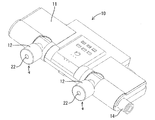
本発明の実施形態1を図1ないし図3によって説明する。この実施形態1では、正極性及び負極性の直流高電圧が交互に印加される例えば1本の放電電極21(以下、共通放電電極21という)と接地電極23とを備えた、いわゆる交流電圧印加タイプの除電装置10を例示する。
<Embodiment 1>
Embodiment 1 of the present invention will be described with reference to FIGS. In the first embodiment, a so-called AC voltage application including, for example, one discharge electrode 21 (hereinafter referred to as a common discharge electrode 21) and a
先に除電装置10の構造について説明する。この除電装置10は、図1に示すように、大まかには空気が供給される空気流通管14などを備える本体部11と、空気流通管14に接続されるとともにコロナ放電により正負のイオンを生成可能なイオン生成室20を備えた一対の可動部12とから構成されている。両可動部12は、本体部11における図示手前側側面において所定の間隔を空けた2位置にそれぞれ設けられており、共に本体部11に対して同図矢線方向に沿って所定の角度範囲内で上下に回動(首振り)可能に支持されている。
First, the structure of the
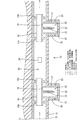
本体部11は、全体が横長な略ブロック状に形成されるとともに、図2に示すように、外装体13内に横方向に沿って貫通する空気流通管14が埋設された構成とされる。この空気流通管14は、図示左側の端部が所定の流量・流圧にて空気を圧送可能な空気供給装置(図示せず)に接続され、図示右側の端部が空気を外部へと排出する排出口(図示せず)に接続されている。この空気流通管14の内部空間が、同図矢線方向に沿って空気が空気供給装置側(上流側)から排出口側(下流側)へ流通する空気流通路15とされる。
As shown in FIG. 2, the
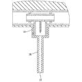
可動部12は、上記した空気流通管14の途中に接続される連結管16と、連結管16の途中から側方へ突出するとともにその内側にイオン生成室20を形成する突出筒部17と、突出筒部17の周りを覆う外装体18とから構成される。連結管16は、空気流通管14の内面から張り出し形成された支持部14aによって空気流通管14に対してその軸線周りに回動可能に支持されており、径寸法が空気流通管14よりも一回り小さい設定とされている。連結管16の側面には、突出筒部17内のイオン生成室20へと連通する空気供給開口19が設けられており、ここを通って空気流通路15からイオン生成室20内へと空気が供給されるようになっている。そして、連結管16の側面における空気供給開口19の隣りからは、先細り状の略円柱状をなす共通放電電極21が突出して設けられている。共通放電電極21は、突出筒部17と同心状に配されるとともに、その尖った先端部が外装体18の空気放出口22よりも内側に配されている。突出筒部17の外周面には、環状をなす接地電極23が設けられるとともに、共通放電電極21を取り囲むようにして配されている。そして、イオン生成室20内に供給された空気は、イオン生成室20の出口である空気放出口22から外部へ放出されるようになっている。また空気放出口22の開口間口は、共通放電電極21の周囲を覆う突出筒部17の口径よりも狭くなっている。
The
さて、本実施形態では、空気流通管14における長さ方向略中央位置(両イオン生成室20の略中間位置)に、空気流通路15を流通する空気の圧力を測定するための圧力センサである圧電素子24が設けられている。
In the present embodiment, the pressure sensor is used to measure the pressure of the air flowing through the
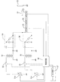
次に本実施形態の回路構成について図3を参照しつつ説明する。同図に示すように、制御回路30からの制御信号レベルに応じて出力電圧振幅を調整可能な一対の交流電圧電源31a,31bの出力が、一対のスイッチ素子32,32の入力側にそれぞれ接続されている。そして、それら一対のスイッチ素子32,32のうち、一方の出力側がトランス33及び負極性の倍電圧整流回路34を介して、他方の出力側がトランス35及び正極性の倍電圧整流回路36を介して共通放電電極21に共通接続されている。制御回路30は、これら一対のスイッチ素子32,32を所定のタイミングで開閉動作させることで共通放電電極21に対して正極電圧と負極電圧とが交互に印加されることになり、もって共通放電電極21から正イオンと負イオンとを交互に生成させることができる。また接地電極23は、アース接続されている。なお両倍電圧整流回路34,36のない回路構成であってもよく、要するに直流電圧を発生させる構成であればよい。
Next, the circuit configuration of the present embodiment will be described with reference to FIG. As shown in the figure, the outputs of a pair of AC
そして、空気流通路15の途中に配された圧電素子24からの出力信号は、空気の供給状況の異常を検出可能な制御回路30に取り込まれるようになっている。制御回路30では、このとき入力される信号のレベルに応じてスイッチ素子32,32を開放して共通放電電極21に対する印加を停止することができるようになっている。
An output signal from the
次に本実施形態の除電装置10の動作を説明する。空気供給装置を駆動させると、空気流通路15に所定の流量・流圧にて空気が供給される。供給される空気の一部は、空気流通路15の途中で両空気供給開口19を通って両イオン生成室20内へと導かれ、それ以外の分については排出口から外部へと排出される。導入された空気がイオン生成室20を通過する過程では、共通放電電極21に正極性及び負極性の直流高電圧が交互に印加されることで、接地電極23との間でコロナ放電が生じ、それに伴って正負のイオンが交互に生成される。このようにして生成された正負のイオンは、空気放出口22を通って外部の帯電体(ICチップなど)にめがけて吹き付けられ、もって帯電体が電気的に中和される。またイオン生成室20及び空気放出口22を備える両可動部12は、既述した通り本体部11に対して所定の角度範囲で回動させることができるので、帯電体に対するイオンの吹き付け角度を適宜に調節することができる(図1参照)。
Next, the operation of the
上記のようにして除電装置10を駆動している間は、常に圧電素子24にて空気流通路15を流通する空気の圧力(流圧)を検出するようにしている。圧電素子24からの出力信号が制御回路30に入力されると、その信号に基づいて得られた圧力の数値と、図示しないメモリに記憶された所定の基準値(例えば、0.05MPa。この値を下回ると、共通放電電極21の周囲で発生するオゾンの量が0.05ppmに達し、そうなると共通放電電極21が腐食するおそれがある。)とを比較し、測定した圧力の数値が基準値以上なら電源電圧の供給を続行し、基準値以下なら異常を検出して両スイッチ素子32,32を共に開放して電源電圧の供給を停止するよう信号を出力する。従って、イオン生成室20内に空気が滞留した状態でコロナ放電を発生させる事態を防ぐことができる。これにより、イオン生成室20内でのオゾン発生量を減少させることができ、もって共通放電電極21がオゾンによって腐食するなどの問題が生じることが防がれる。
While the
以上説明したように本実施形態によれば、空気流通路15における空気の流圧を圧電素子24にて測定することで、空気の供給状況(滞留状況)の異常を検出するようにしたから、従来のように温度を測定するものと比較すると、除電装置10の使用環境に左右されることなく、空気が滞留しているか否かを確実に検出することができる。しかも、仮に感熱素子にて空気の流量を測定したものと比較すると、素子自体の数が少なく済むとともに、また加熱手段も不要となるから、構成の簡素化などを図ることができる。さらには、空気の流圧を測定するようにしたから、従来のように温度を測定するものと比較すると、空気の供給状況の変化に対する応答性が高いので、例えば帯電体が搬送されるタイミングに合わせて空気の供給を断続的に行う場合でも、正確な異常検出を期することができる。
As described above, according to the present embodiment, the air flow pressure in the
さらには、異常が検出されたときに共通放電電極21への印加を停止させるようにしたから、イオン生成室20内に空気が滞留した状態でコロナ放電を発生させることがなく、もってオゾンの発生を抑制することができる。
Furthermore, since the application to the
<変形例>
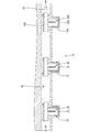
上記した実施形態1の変形例を図4によって説明する。この変形例では、可動部12(イオン生成室20)を3つ備えた除電装置10において、圧電素子24の配置を上記実施形態1とは異ならせたものを例示する。なおこの変形例では、最も下流側の可動部12に関しては、他の2つの可動部12と区別するために符号に添え字Aを付すものとする。
<Modification>
A modification of the first embodiment will be described with reference to FIG. In this modification, in the
圧電素子24は、空気流通路15のうち最も下流側に配置された可動部12A(空気放出口22A)の近傍に配されている。詳しくは、圧電素子24は、空気流通路15における排出口側の端部と、最も下流側の可動部12Aにおける連結管16Aとの間に配置されており、この位置では流通する空気の流圧が、空気流通路15において最も低くなっている。つまり、この変形例では、空気流通路15において最も空気が滞留し易い箇所にて空気の流圧を測定するようにしているから、空気の供給異常を確実に検出することができる。これにより、最も下流側のイオン生成室20A内に空気の滞留した状態でコロナ放電を発生させるのが防がれ、オゾンの発生量を有効に抑制することができる。
The
<実施形態2>
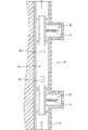
本発明の実施形態2を図5または図6によって説明する。この実施形態2では、上記した実施形態1における圧電素子24に代えて熱式流量センサである感熱素子25,26を用い、空気の流量を測定するようにした場合を示す。なおこの実施形態2では、上記した実施形態1と同様の構造、作用及び効果について重複する説明は省略する。
<Embodiment 2>
A second embodiment of the present invention will be described with reference to FIG. 5 or FIG. In the second embodiment, a case is shown in which the
先に本実施形態の除電装置10の構造を説明する。図5に示すように、空気流通管14における略中央部分には、一対の感熱素子25,26が互いに所定の距離を空けた状態で配置されている。両感熱素子25,26は、空気流通路15に沿って上流側と下流側とにそれぞれ配されている。また下流側の感熱素子26の近くには、加熱手段27(図5では図示を省略する)が設けられている。
The structure of the
次に本実施形態の回路構成について図6を参照しつつ説明する。同図に示すように、両感熱素子25,26及び加熱手段27からの出力信号が制御回路30に取り込まれるようになっている。制御回路30では、このとき入力される信号のレベルに応じてスイッチ素子32,32を開放して共通放電電極21に対する印加を停止することができるようになっている。
Next, the circuit configuration of the present embodiment will be described with reference to FIG. As shown in the figure, output signals from both the
次に本実施形態の除電装置10の動作を説明する。除電装置10が駆動している間は、常に両感熱素子25,26及び加熱手段27にて空気流通路15を流通する空気の流量を検出するようにしている。詳しくは、下流側の感熱素子26を加熱手段27により加熱し、上流側の感熱素子25と下流側の感熱素子26とで測定される温度の差が所定値になるように加熱手段27における発熱量を制御しておく。このときの発熱量は、空気流通路15を流通する空気の流量に比例することになるから、加熱手段27の発熱量に基づいて空気の流量が得られる。これにより得られた空気の流量と、図示しないメモリに記憶された所定の基準値とを比較し、測定した空気の流量の数値が基準値以上なら電源電圧の供給を続行し、基準値以下なら異常を検出して両スイッチ素子32,32を共に開放して電源電圧の供給を停止するよう信号を出力する。従って、イオン生成室20内に空気が滞留した状態でコロナ放電を発生させる事態を防ぐことができる。これにより、イオン生成室20内でのオゾン発生量を減少させることができ、もって共通放電電極21がオゾンによって腐食するなどの問題が生じることが防がれる。
Next, the operation of the
以上説明したように本実施形態によれば、空気流通路15における空気の流量を測定することで、空気の供給状況の異常を検出するようにしたから、従来のように温度を測定したものと比較すると、除電装置10の使用環境に左右されることなく、空気が滞留しているか否かを確実に検出することができる。
As described above, according to the present embodiment, since the abnormality in the air supply status is detected by measuring the flow rate of air in the
<他の実施形態>
本発明は上記記述及び図面によって説明した実施形態に限定されるものではなく、例えば次のような実施形態も本発明の技術的範囲に含まれ、さらに、下記以外にも要旨を逸脱しない範囲内で種々変更して実施することができる。
<Other embodiments>
The present invention is not limited to the embodiments described with reference to the above description and drawings. For example, the following embodiments are also included in the technical scope of the present invention, and further, within the scope not departing from the gist of the invention other than the following. Various modifications can be made.
(1)上記した実施形態1及び2では、異常検出時にコロナ放電を停止させるものを示したが、外部へ異常検出の出力を行うようにしてもよい。詳しくは、異常が検出されたとき、出力回路37(図3及び図6の二点差線で囲んだ部分)を介して異常検知信号を出力するようにし、その出力信号に基づいて、例えば外部に配設した異常検出LEDを点灯させて作業者に報知するようにしてもよい。このようにすれば、作業者にメンテナンスなどの適切な処置を行うよう促すことができる。また異常検知信号の出力に基づいて、除電装置10に向けて帯電体を順次に送り込む移動装置の駆動を停止させるようにしてもよい。このようにすれば、帯電体が除電されなくなる事態を自動的に防ぐことができる。
(1) In the first and second embodiments described above, the corona discharge is stopped when an abnormality is detected. However, an abnormality detection output may be performed to the outside. Specifically, when an abnormality is detected, an abnormality detection signal is output via the output circuit 37 (the portion surrounded by the two-dot chain line in FIGS. 3 and 6), and based on the output signal, for example, externally You may make it alert | report to an operator by lighting the arrange | positioned abnormality detection LED. In this way, it is possible to urge the operator to take appropriate measures such as maintenance. Further, based on the output of the abnormality detection signal, the driving of the moving device that sequentially feeds the charged bodies toward the
(2)上記した実施形態2の変形例として、可動部12(イオン生成室20)を3つ備えた除電装置において、両感熱素子25,26を空気流通路15のうち最も下流側に配置された可動部12の近傍に配するようにしてもよい。このものにおいても、既述した実施形態1の変形例と同様に、空気流通路15において最も空気が滞留し易い箇所にて空気の流量を測定することができるから、空気の供給異常を確実に検出することができる。
(2) As a modification of the above-described second embodiment, in a static eliminator including three movable parts 12 (ion generation chambers 20), both
(3)その他の変形例としては、1つの除電装置に圧電素子24と、両感熱素子25,26及び加熱手段27を設けるようにし、空気の流圧の数値と、空気の流量の数値とが共に、所定の基準値を満たしていないときにのみ、異常を検出するようにしてもよい。
(3) As another modification, the
(4)可動部12(イオン生成室20及び共通放電電極21)の数や配置などについては、任意に変更可能である。また、図7に示すように、外装体18に細長い筒状をなすノズル28を一体形成し、空気放出口22の位置を変更するようにしても構わない。
(4) The number and arrangement of the movable parts 12 (
(5)上記した実施形態では、いわゆる交流電圧印加タイプの除電装置を例示したが、その他にも例えば正極性及び負極性の直流高電圧がそれぞれ印加される正負一対の放電電極を備えた、いわゆる直流電圧印加タイプの除電装置にも本発明は適用可能である。 (5) In the above-described embodiment, a so-called AC voltage application type static eliminator has been exemplified. In addition, for example, a so-called AC voltage application type static eliminator is provided. The present invention is also applicable to a DC voltage application type static eliminator.
10…除電装置
15…空気流通路(空気供給路)
20…イオン生成室(空気供給路)
21…共通放電電極(放電電極)
22…空気放出口
24…圧電素子(空気流測定手段)
25,26…感熱素子(空気流測定手段)
27…加熱手段(空気流測定手段)
30…制御回路(異常検出手段、制御手段)
31a,31b…交流電圧電源(電圧電源)
37…出力回路(出力手段)
10 ...
20 ... Ion generation chamber (air supply path)
21 ... Common discharge electrode (discharge electrode)
22 ...
25, 26 ... thermal element (air flow measuring means)
27. Heating means (air flow measuring means)
30. Control circuit (abnormality detection means, control means)
31a, 31b ... AC voltage power supply (voltage power supply)
37 ... Output circuit (output means)
Claims (6)
周囲が覆われるとともに、電圧電源により電圧が印加されることでコロナ放電を発生して正負のイオンを生成可能な放電電極と、
前記放電電極で生成されたイオンを前記空気供給路から外部に放出するための空気放出口と、
前記空気供給路における空気の流量または流圧を測定するための空気流測定手段と、
空気流測定手段の測定結果に基づいて空気の供給状況の異常を検出するための異常検出手段とを備えていることを特徴とする除電装置。 An air supply path through which air is supplied;
A discharge electrode capable of generating positive and negative ions by generating a corona discharge when a voltage is applied by a voltage power source while the surroundings are covered,
An air discharge port for discharging ions generated by the discharge electrode to the outside from the air supply path;
Air flow measuring means for measuring the flow rate or flow pressure of air in the air supply path;
An antistatic device, comprising: an abnormality detecting means for detecting an abnormality in an air supply status based on a measurement result of the air flow measuring means.
前記空気流測定手段は、空気供給路における最も下流側の空気放出口の近傍に配されていることを特徴とする請求項1記載の除電装置。 A plurality of the air discharge port and the discharge electrode are provided on the upstream side and the downstream side in the air supply path,
2. The static eliminator according to claim 1, wherein the air flow measuring means is disposed in the vicinity of the most downstream air discharge port in the air supply path.
Priority Applications (1)
| Application Number | Priority Date | Filing Date | Title |
|---|---|---|---|
| JP2004106648A JP4497524B2 (en) | 2004-03-31 | 2004-03-31 | Static eliminator |
Applications Claiming Priority (1)
| Application Number | Priority Date | Filing Date | Title |
|---|---|---|---|
| JP2004106648A JP4497524B2 (en) | 2004-03-31 | 2004-03-31 | Static eliminator |
Publications (2)
| Publication Number | Publication Date |
|---|---|
| JP2005294004A true JP2005294004A (en) | 2005-10-20 |
| JP4497524B2 JP4497524B2 (en) | 2010-07-07 |
Family
ID=35326712
Family Applications (1)
| Application Number | Title | Priority Date | Filing Date |
|---|---|---|---|
| JP2004106648A Expired - Lifetime JP4497524B2 (en) | 2004-03-31 | 2004-03-31 | Static eliminator |
Country Status (1)
| Country | Link |
|---|---|
| JP (1) | JP4497524B2 (en) |
Cited By (8)
| Publication number | Priority date | Publication date | Assignee | Title |
|---|---|---|---|---|
| JP2007305403A (en) * | 2006-05-11 | 2007-11-22 | Omron Corp | Corona discharge ionizer, fan unit, and clean room system |
| JP2008171648A (en) * | 2007-01-10 | 2008-07-24 | Sunx Ltd | Static eliminator |
| JP2009285628A (en) * | 2008-05-30 | 2009-12-10 | Sunx Ltd | Apparatus for removing static electricity and dust |
| JP2010000484A (en) * | 2008-06-23 | 2010-01-07 | Sunx Ltd | Charge/dust removal apparatus |
| JP2012182054A (en) * | 2011-03-02 | 2012-09-20 | Kasuga Electric Works Ltd | Explosion-proof discharge device |
| JP2017158277A (en) * | 2016-03-01 | 2017-09-07 | Smc株式会社 | High-voltage generating circuit |
| JPWO2022018873A1 (en) * | 2020-07-22 | 2022-01-27 | ||
| CN121077225A (en) * | 2025-10-31 | 2025-12-05 | 益能电焰科技(深圳)有限公司 | High-voltage circuit for electric flame range |
Citations (4)
| Publication number | Priority date | Publication date | Assignee | Title |
|---|---|---|---|---|
| JPH04370697A (en) * | 1991-06-20 | 1992-12-24 | Takasago Thermal Eng Co Ltd | Charged object neutralizing device |
| JPH06152004A (en) * | 1992-11-13 | 1994-05-31 | Komatsu Ltd | Pulse laser device |
| JPH09108313A (en) * | 1995-10-24 | 1997-04-28 | Mitsubishi Electric Corp | Method and apparatus for preventing microbial reproduction |
| JP2001297854A (en) * | 2000-04-14 | 2001-10-26 | Keyence Corp | Corona discharge lamp |
-
2004
- 2004-03-31 JP JP2004106648A patent/JP4497524B2/en not_active Expired - Lifetime
Patent Citations (4)
| Publication number | Priority date | Publication date | Assignee | Title |
|---|---|---|---|---|
| JPH04370697A (en) * | 1991-06-20 | 1992-12-24 | Takasago Thermal Eng Co Ltd | Charged object neutralizing device |
| JPH06152004A (en) * | 1992-11-13 | 1994-05-31 | Komatsu Ltd | Pulse laser device |
| JPH09108313A (en) * | 1995-10-24 | 1997-04-28 | Mitsubishi Electric Corp | Method and apparatus for preventing microbial reproduction |
| JP2001297854A (en) * | 2000-04-14 | 2001-10-26 | Keyence Corp | Corona discharge lamp |
Cited By (13)
| Publication number | Priority date | Publication date | Assignee | Title |
|---|---|---|---|---|
| JP2007305403A (en) * | 2006-05-11 | 2007-11-22 | Omron Corp | Corona discharge ionizer, fan unit, and clean room system |
| JP2008171648A (en) * | 2007-01-10 | 2008-07-24 | Sunx Ltd | Static eliminator |
| JP2009285628A (en) * | 2008-05-30 | 2009-12-10 | Sunx Ltd | Apparatus for removing static electricity and dust |
| JP2010000484A (en) * | 2008-06-23 | 2010-01-07 | Sunx Ltd | Charge/dust removal apparatus |
| JP2012182054A (en) * | 2011-03-02 | 2012-09-20 | Kasuga Electric Works Ltd | Explosion-proof discharge device |
| CN107147308A (en) * | 2016-03-01 | 2017-09-08 | Smc株式会社 | high voltage generating circuit |
| JP2017158277A (en) * | 2016-03-01 | 2017-09-07 | Smc株式会社 | High-voltage generating circuit |
| JPWO2022018873A1 (en) * | 2020-07-22 | 2022-01-27 | ||
| WO2022018873A1 (en) * | 2020-07-22 | 2022-01-27 | 株式会社日立ハイテク | Dc high-voltage source device and charged particle beam device |
| GB2611697A (en) * | 2020-07-22 | 2023-04-12 | Hitachi High Tech Corp | DC high-voltage source device and charged particle beam device |
| JP7519442B2 (en) | 2020-07-22 | 2024-07-19 | 株式会社日立ハイテク | DC high voltage power supply and charged particle beam device |
| US12525883B2 (en) | 2020-07-22 | 2026-01-13 | Hitachi High-Tech Corporation | DC high-voltage source device including plurality of variable DC voltage sources and plurality of switching circuits, and charged particle beam device including the DC high-voltage source device |
| CN121077225A (en) * | 2025-10-31 | 2025-12-05 | 益能电焰科技(深圳)有限公司 | High-voltage circuit for electric flame range |
Also Published As
| Publication number | Publication date |
|---|---|
| JP4497524B2 (en) | 2010-07-07 |
Similar Documents
| Publication | Publication Date | Title |
|---|---|---|
| US8018710B2 (en) | Ionizer and static elimination method | |
| JP4412357B2 (en) | Air flow measurement device | |
| JP4497524B2 (en) | Static eliminator | |
| US20140069210A1 (en) | Flowmeter | |
| JP2010276549A (en) | Exhaust gas analyzer and probe unit | |
| US20150233746A1 (en) | Differential pressure type flowmeter and flow controller provided with the same | |
| US10451597B2 (en) | Determination device | |
| KR101390130B1 (en) | Air Ion Measuring Device | |
| WO2018100887A1 (en) | Physical quantity measuring device, abnormality detection device, and abnormality detection method | |
| ES2654938T3 (en) | Plasma spray device, as well as a method to control the status of a plasma spray device | |
| WO2019049429A1 (en) | Fluid property detection device | |
| US20050063130A1 (en) | Electrical ionizer | |
| TWI698627B (en) | Liquid sensing device and sensing method thereof | |
| CN107110696A (en) | Thermal type flow measuring apparatus with diagnostic function | |
| JP4170945B2 (en) | Leak inspection system | |
| CN110940464B (en) | Water leakage detection method and water leakage detection device | |
| JP2004127858A (en) | Static eliminator | |
| CN112640584A (en) | Gas supply determination method and plasma generator | |
| JP5150571B2 (en) | Electrode type leak detector | |
| JP2017201293A (en) | Judgment device | |
| US9874416B2 (en) | Cooling device having function to detect clogging of radiation fins | |
| JP4388059B2 (en) | Anomaly detection device for painted surface ground inspection device | |
| US20070125167A1 (en) | Fluid flow detecting apparatus | |
| JP2009216550A (en) | Correction value inspection method of thermistor for heating detection, and control method of device equipped with thermistor for heating detection | |
| CN108225613A (en) | A kind of blown using strut reduces the temperature probe of strut blockage effect |
Legal Events
| Date | Code | Title | Description |
|---|---|---|---|
| A621 | Written request for application examination |
Free format text: JAPANESE INTERMEDIATE CODE: A621 Effective date: 20070209 |
|
| RD04 | Notification of resignation of power of attorney |
Free format text: JAPANESE INTERMEDIATE CODE: A7424 Effective date: 20070709 |
|
| RD04 | Notification of resignation of power of attorney |
Free format text: JAPANESE INTERMEDIATE CODE: A7424 Effective date: 20070710 |
|
| RD02 | Notification of acceptance of power of attorney |
Free format text: JAPANESE INTERMEDIATE CODE: A7422 Effective date: 20090924 |
|
| RD04 | Notification of resignation of power of attorney |
Free format text: JAPANESE INTERMEDIATE CODE: A7424 Effective date: 20090924 |
|
| A131 | Notification of reasons for refusal |
Free format text: JAPANESE INTERMEDIATE CODE: A131 Effective date: 20091117 |
|
| A521 | Request for written amendment filed |
Free format text: JAPANESE INTERMEDIATE CODE: A523 Effective date: 20100118 |
|
| TRDD | Decision of grant or rejection written | ||
| A01 | Written decision to grant a patent or to grant a registration (utility model) |
Free format text: JAPANESE INTERMEDIATE CODE: A01 Effective date: 20100408 |
|
| A01 | Written decision to grant a patent or to grant a registration (utility model) |
Free format text: JAPANESE INTERMEDIATE CODE: A01 |
|
| A61 | First payment of annual fees (during grant procedure) |
Free format text: JAPANESE INTERMEDIATE CODE: A61 Effective date: 20100412 |
|
| FPAY | Renewal fee payment (event date is renewal date of database) |
Free format text: PAYMENT UNTIL: 20130423 Year of fee payment: 3 |
|
| R150 | Certificate of patent or registration of utility model |
Ref document number: 4497524 Country of ref document: JP Free format text: JAPANESE INTERMEDIATE CODE: R150 Free format text: JAPANESE INTERMEDIATE CODE: R150 |
|
| FPAY | Renewal fee payment (event date is renewal date of database) |
Free format text: PAYMENT UNTIL: 20130423 Year of fee payment: 3 |
|
| S533 | Written request for registration of change of name |
Free format text: JAPANESE INTERMEDIATE CODE: R313533 |
|
| FPAY | Renewal fee payment (event date is renewal date of database) |
Free format text: PAYMENT UNTIL: 20130423 Year of fee payment: 3 |
|
| R350 | Written notification of registration of transfer |
Free format text: JAPANESE INTERMEDIATE CODE: R350 |
|
| FPAY | Renewal fee payment (event date is renewal date of database) |
Free format text: PAYMENT UNTIL: 20130423 Year of fee payment: 3 |
|
| FPAY | Renewal fee payment (event date is renewal date of database) |
Free format text: PAYMENT UNTIL: 20140423 Year of fee payment: 4 |
|
| R250 | Receipt of annual fees |
Free format text: JAPANESE INTERMEDIATE CODE: R250 |
|
| R250 | Receipt of annual fees |
Free format text: JAPANESE INTERMEDIATE CODE: R250 |
|
| R250 | Receipt of annual fees |
Free format text: JAPANESE INTERMEDIATE CODE: R250 |
|
| R250 | Receipt of annual fees |
Free format text: JAPANESE INTERMEDIATE CODE: R250 |
|
| R250 | Receipt of annual fees |
Free format text: JAPANESE INTERMEDIATE CODE: R250 |
|
| R250 | Receipt of annual fees |
Free format text: JAPANESE INTERMEDIATE CODE: R250 |
|
| R250 | Receipt of annual fees |
Free format text: JAPANESE INTERMEDIATE CODE: R250 |
|
| R250 | Receipt of annual fees |
Free format text: JAPANESE INTERMEDIATE CODE: R250 |
|
| R250 | Receipt of annual fees |
Free format text: JAPANESE INTERMEDIATE CODE: R250 |
|
| R250 | Receipt of annual fees |
Free format text: JAPANESE INTERMEDIATE CODE: R250 |
|
| R250 | Receipt of annual fees |
Free format text: JAPANESE INTERMEDIATE CODE: R250 |
|
| EXPY | Cancellation because of completion of term |