JP2005294330A - Method of manufacturing ferrite magnet - Google Patents
Method of manufacturing ferrite magnet Download PDFInfo
- Publication number
- JP2005294330A JP2005294330A JP2004103416A JP2004103416A JP2005294330A JP 2005294330 A JP2005294330 A JP 2005294330A JP 2004103416 A JP2004103416 A JP 2004103416A JP 2004103416 A JP2004103416 A JP 2004103416A JP 2005294330 A JP2005294330 A JP 2005294330A
- Authority
- JP
- Japan
- Prior art keywords
- ferrite magnet
- magnet
- ferrite
- preform
- density
- Prior art date
- Legal status (The legal status is an assumption and is not a legal conclusion. Google has not performed a legal analysis and makes no representation as to the accuracy of the status listed.)
- Pending
Links
- 229910000859 α-Fe Inorganic materials 0.000 title claims abstract description 62
- 238000004519 manufacturing process Methods 0.000 title claims abstract description 18
- 239000000463 material Substances 0.000 claims abstract description 35
- 239000008187 granular material Substances 0.000 claims abstract description 33
- 239000000843 powder Substances 0.000 claims description 45
- 238000000465 moulding Methods 0.000 claims description 14
- 239000002245 particle Substances 0.000 claims description 12
- 238000003825 pressing Methods 0.000 claims description 5
- 229910052712 strontium Inorganic materials 0.000 claims description 5
- 238000010304 firing Methods 0.000 claims description 4
- 229910052788 barium Inorganic materials 0.000 claims description 3
- 229910052791 calcium Inorganic materials 0.000 claims description 3
- 239000013078 crystal Substances 0.000 claims description 3
- 229910052761 rare earth metal Inorganic materials 0.000 claims description 3
- 229910052725 zinc Inorganic materials 0.000 claims description 3
- 229910052745 lead Inorganic materials 0.000 claims description 2
- 229910052746 lanthanum Inorganic materials 0.000 abstract description 7
- 238000000034 method Methods 0.000 description 21
- 239000000203 mixture Substances 0.000 description 13
- 229910004298 SiO 2 Inorganic materials 0.000 description 11
- 239000002994 raw material Substances 0.000 description 9
- 230000000052 comparative effect Effects 0.000 description 8
- 238000010298 pulverizing process Methods 0.000 description 8
- XLYOFNOQVPJJNP-UHFFFAOYSA-N water Substances O XLYOFNOQVPJJNP-UHFFFAOYSA-N 0.000 description 8
- 238000011049 filling Methods 0.000 description 6
- 230000004907 flux Effects 0.000 description 5
- 238000005469 granulation Methods 0.000 description 3
- 230000003179 granulation Effects 0.000 description 3
- 238000002156 mixing Methods 0.000 description 3
- 239000000047 product Substances 0.000 description 3
- 238000007493 shaping process Methods 0.000 description 3
- 239000007858 starting material Substances 0.000 description 3
- 238000005406 washing Methods 0.000 description 3
- DSSYKIVIOFKYAU-XCBNKYQSSA-N (R)-camphor Chemical compound C1C[C@@]2(C)C(=O)C[C@@H]1C2(C)C DSSYKIVIOFKYAU-XCBNKYQSSA-N 0.000 description 2
- 241000723346 Cinnamomum camphora Species 0.000 description 2
- 229910020599 Co 3 O 4 Inorganic materials 0.000 description 2
- 239000011230 binding agent Substances 0.000 description 2
- 239000011575 calcium Substances 0.000 description 2
- CJZGTCYPCWQAJB-UHFFFAOYSA-L calcium stearate Chemical compound [Ca+2].CCCCCCCCCCCCCCCCCC([O-])=O.CCCCCCCCCCCCCCCCCC([O-])=O CJZGTCYPCWQAJB-UHFFFAOYSA-L 0.000 description 2
- 235000013539 calcium stearate Nutrition 0.000 description 2
- 239000008116 calcium stearate Substances 0.000 description 2
- 229960000846 camphor Drugs 0.000 description 2
- 229930008380 camphor Natural products 0.000 description 2
- 238000007906 compression Methods 0.000 description 2
- 230000006835 compression Effects 0.000 description 2
- 238000000748 compression moulding Methods 0.000 description 2
- 238000007796 conventional method Methods 0.000 description 2
- 238000010586 diagram Methods 0.000 description 2
- 239000002612 dispersion medium Substances 0.000 description 2
- 239000012467 final product Substances 0.000 description 2
- -1 for example Substances 0.000 description 2
- 229910052742 iron Inorganic materials 0.000 description 2
- 239000011812 mixed powder Substances 0.000 description 2
- 239000002002 slurry Substances 0.000 description 2
- 239000007787 solid Substances 0.000 description 2
- 238000000859 sublimation Methods 0.000 description 2
- 230000008022 sublimation Effects 0.000 description 2
- 239000000654 additive Substances 0.000 description 1
- 230000000996 additive effect Effects 0.000 description 1
- 229910052797 bismuth Inorganic materials 0.000 description 1
- 238000001354 calcination Methods 0.000 description 1
- 238000005336 cracking Methods 0.000 description 1
- 230000006866 deterioration Effects 0.000 description 1
- 238000005516 engineering process Methods 0.000 description 1
- 230000002093 peripheral effect Effects 0.000 description 1
- 229920002635 polyurethane Polymers 0.000 description 1
- 239000004814 polyurethane Substances 0.000 description 1
- 238000010008 shearing Methods 0.000 description 1
Images
Landscapes
- Press-Shaping Or Shaping Using Conveyers (AREA)
- Hard Magnetic Materials (AREA)
- Manufacturing Cores, Coils, And Magnets (AREA)
- Magnetic Ceramics (AREA)
Abstract
Description
本発明は、円筒状のフェライト磁石の製造方法に関する。 The present invention relates to a method for manufacturing a cylindrical ferrite magnet.
従来の圧縮成形法に基づく2極異方性円筒状フェライト磁石(以下、単にフェライト磁石と称する)の製造においては、所要の金型に充填されたフェライト磁石粉末に対して、磁界を印加しながら予備的な成形を施した予備成形体を解砕して顆粒材にしたもの(以下、磁場顆粒材と呼ぶ)を出発原料として用いるのが一般的である。しかしながら、従来のこの種の磁場顆粒材では金型への充填性が不十分であったために、材料の充填性が悪いときには製品の寸法バラツキが大きくなったり、クラックが発生しやすくなる等の問題が生じる。このため、寸法のバラツキやクラック発生等の生産性上の問題点から、圧縮方向の高さ寸法(L)と外径(R)との比(L/R)が2.0以上のフェライト磁石を、工業的に安定した状態で製造するのは極めて困難であった。 In the production of a bipolar anisotropic cylindrical ferrite magnet (hereinafter simply referred to as a ferrite magnet) based on a conventional compression molding method, a magnetic field is applied to a ferrite magnet powder filled in a required mold. In general, a preform formed by preliminarily molding is crushed into granules (hereinafter referred to as magnetic field granules) as a starting material. However, since this type of magnetic field granule material has insufficient filling ability in the mold, problems such as large dimensional variation of the product or prone to cracks occur when the filling ability of the material is poor. Occurs. Therefore, a ferrite magnet having a ratio (L / R) between the height dimension (L) in the compression direction and the outer diameter (R) of 2.0 or more due to productivity problems such as dimensional variation and cracking. It was extremely difficult to produce the product in an industrially stable state.
従って、上記材料の充填性をできるだけ向上させることが重要である。そして、このような状態を実現するために必要なことは、その充填性の向上を阻害している材料内の含有微粉を可能な限り少なくすることである。
しかしながら、磁場顆粒材として従来のものを用いたときには、その分級処理・造粒処理や解砕処理等を適用して当該材料の含有微粉を少なくすると、最終製品の磁気特性が低下してしまうという難点があり、目標の磁石を製造する際の材料の充填性を十分に高めることは不可能であった。
Therefore, it is important to improve the filling property of the material as much as possible. And what is necessary to realize such a state is to reduce the contained fine powder in the material that hinders the improvement of the filling property as much as possible.
However, when the conventional magnetic granule material is used, if the classification process, granulation process, pulverization process, etc. are applied to reduce the content fine powder of the material, the magnetic properties of the final product will be reduced. There is a difficulty, and it has been impossible to sufficiently increase the filling property of the material when manufacturing the target magnet.
そこで、本出願人は、製品の高磁気特性と使用材料の高充填性との両立を目標として研究に努め、予備成形の処理に工夫を施すことにより、磁場顆粒材における微粉の含有割合を少なくした場合であっても、最終製品の磁気特性が劣化しない磁場顆粒材を得ることに成功した(特許文献1参照)。
即ち、本出願人が開発した手法によれば、フェライト磁石粉末に磁界を印加しながら乾式成形法によって得た予備成形体について、解砕処理を施すことによって顆粒材にしたものを出発原料とする。そして、この出発原料を所定の成形金型に充填して、磁界を印加しながら加圧・成形を実行する。ここで、予備成形体の密度については理論密度の42%以上51%以下とし、また、顆粒材に含まれる75μm以下の粒子比率を10wt%以下にすることにより、磁気特性の劣化がない磁場顆粒材を得ることができる。このようにして得た磁場顆粒材を用いることにより、良好な磁気特性を有する所望のフェライト磁石を製造することが可能となる。
このようにして、従来では製造が困難であった、高さ方向の寸法(L)と外径(R)との比(L/R)が2.0以上のフェライト磁石を製造することが可能となった。
Therefore, the present applicant strives for research with the goal of achieving both high magnetic properties of the product and high fillability of the materials used, and by devising the preforming process, the content ratio of fine powder in the magnetic granule material is reduced. Even in this case, a magnetic field granule material that does not deteriorate the magnetic properties of the final product was successfully obtained (see Patent Document 1).
That is, according to the technique developed by the present applicant, the preformed material obtained by the dry molding method while applying a magnetic field to the ferrite magnet powder is used as a starting material that is granulated by crushing treatment. . Then, the starting material is filled in a predetermined molding die, and pressing and molding are performed while applying a magnetic field. Here, the density of the preform is set to 42% or more and 51% or less of the theoretical density, and the particle ratio of 75 μm or less contained in the granule material is set to 10 wt% or less, thereby preventing magnetic properties from being deteriorated. A material can be obtained. By using the magnetic field granule thus obtained, it becomes possible to produce a desired ferrite magnet having good magnetic properties.
Thus, it is possible to manufacture a ferrite magnet having a ratio (L / R) of the dimension (L) in the height direction to the outer diameter (R) of 2.0 or more, which has conventionally been difficult to manufacture. It became.
しかしながら、この方法で製造したフェライト磁石は、特に高強度が要求される用途の場合、磁気特性は満足しつつも、強度が不足するという問題があった。このような用途としては、例えば、洗濯機や皿洗い機等に用いられるウォーターポンプ用のモータに組み込まれるマグネットがある。ウォーターポンプのマグネットは、ウォーターポンプを駆動するためのモータにおいて、回転駆動力を発生するロータの一部を構成する。ロータは、回転シャフトとその外周部に一体に設けられたマグネットとから構成され、このマグネットとして、円筒状のフェライト磁石が用いられる。このようなモータでは、高トルクを発生するため、ロータが回転を開始するときや回転を停止するときに、慣性により回転シャフトとマグネットとの間にせん断力が作用し、これによってマグネットが破損したり、回転シャフトから脱落したりするという問題が生じるのである。
本発明は、このような技術的課題に基づいてなされたもので、高強度を有する円筒状のフェライト磁石を形成できるフェライト磁石の製造方法を提供することを目的とする。
However, the ferrite magnet manufactured by this method has a problem in that the strength is insufficient while satisfying the magnetic characteristics, particularly in applications where high strength is required. As such an application, for example, there is a magnet incorporated in a motor for a water pump used in a washing machine, a dishwasher or the like. The magnet of the water pump constitutes a part of a rotor that generates a rotational driving force in a motor for driving the water pump. The rotor is composed of a rotating shaft and a magnet integrally provided on the outer peripheral portion thereof, and a cylindrical ferrite magnet is used as the magnet. In such a motor, a high torque is generated. Therefore, when the rotor starts rotating or stops rotating, a shearing force acts between the rotating shaft and the magnet due to inertia, which causes the magnet to break. Or a problem of falling off the rotating shaft.
The present invention has been made based on such a technical problem, and an object thereof is to provide a method of manufacturing a ferrite magnet capable of forming a cylindrical ferrite magnet having high strength.
かかる目的のもと、本発明のフェライト磁石の製造方法は、フェライト磁石材料を、磁界を印加しながら加圧成形し、予備成形体を得る予備成形工程と、予備成形体を解砕して顆粒材(磁場顆粒材)を得る解砕工程と、得られた顆粒材を、磁界を印加しながら加圧成形して本成形体を得る本成形工程と、本成形体を焼成して、焼成体を得る焼成工程と、焼成体を加工して、円筒状で、外径(R)とその中心軸線方向の長さ(L)との比(L/R)が2.0以上の磁石体を得る加工工程と、を備え、予備成形工程では、予備成形体の密度が理論密度の51%を上回り、かつ57%以下となるようにフェライト磁石材料を加圧成形することを特徴とする。
このように、予備成形体の密度を上記範囲とすることで、円筒状で長尺のフェライト磁石を高強度なものとすることができる。また、予備成形体の密度を上記範囲とすることにより、解砕によって得られる顆粒の顆粒内密度も高くなり、充填性も向上する。
また、予備成形工程では、フェライト磁石材料としてフェライト磁石粉末を用い、予備成形を粉末状態のまま乾式で行うのが好ましい。
For this purpose, the method for producing a ferrite magnet according to the present invention includes a preforming step in which a ferrite magnet material is pressure-formed while applying a magnetic field to obtain a preform, and the preform is crushed and granulated. A crushing step for obtaining a material (magnetic granule material), a main forming step for press-molding the obtained granule material while applying a magnetic field to obtain a main molded body, and firing the main molded body, And firing the sintered body to obtain a cylindrical magnet body having an outer diameter (R) and a length (L) in the direction of the central axis (L / R) of 2.0 or more. A pre-molding step, wherein the ferrite magnet material is pressure-molded so that the density of the preform exceeds 51% of the theoretical density and is 57% or less.
Thus, by setting the density of the preform to the above range, a cylindrical and long ferrite magnet can be made high in strength. Moreover, the density in a granule obtained by crushing also becomes high by making the density of a preform into the above-mentioned range, and the filling property improves.
In the preforming step, it is preferable to use a ferrite magnet powder as the ferrite magnet material and perform the preforming in a dry state in a powder state.
ところで、解砕工程では、顆粒材の平均粒径が0.1mm以上0.4mm未満となるよう、予備成形体を解砕するのが好ましい。これには、解砕工程で、メッシュサイズが#40を超え#70以下のスクリーンに、予備成形体を通すことで顆粒材を得るのが好ましい。
By the way, in the crushing step, it is preferable to crush the preform so that the average particle diameter of the granule is 0.1 mm or more and less than 0.4 mm. For this, it is preferable to obtain a granule material by passing a preformed body through a screen having a mesh
このような磁石体としては、六方晶構造を有するフェライトを主相とし、式(1) A1−xRx(Fe12−yMy)zO19 (ただし、AはSr、Ba、CaおよびPbから選択され、Srを必須とする少なくとも1種の元素、Rは希土類元素(Yを含む)およびBiから選択され、Laを必須とする少なくとも1種の元素、MはCo、またはCoおよびZn、x、y、zはモル数)で表され、
0.04≦x≦0.5
0.04≦y≦0.5
0.7 ≦z≦1.2
1≦(x/y)
であるものが好適である。
As such a magnet body, a ferrite having a hexagonal crystal structure is used as a main phase, and the formula (1) A 1-x R x (Fe 12-y M y ) z O 19 (where A is Sr, Ba, Ca And at least one element selected from Sb, R is selected from rare earth elements (including Y) and Bi, and at least one element required from La, M is Co, or Co and Zn, x, y, z are expressed in moles)
0.04 ≦ x ≦ 0.5
0.04 ≦ y ≦ 0.5
0.7 ≦ z ≦ 1.2
1 ≦ (x / y)
Are preferred.
特許文献1にも記載されているように、予備成形体の密度が高いと、これを解砕して得られる磁場顆粒材における顆粒内の密度も高くなる。そして、この顆粒内の密度が高いときには、その成形のために加圧・圧縮力が加わったときに、顆粒が潰れる可能性は極めて低い。この場合において、顆粒に加わる加圧・圧縮力だけではなく、他の顆粒からの摩擦力も大きくなり、顆粒の配向が磁界印加方向から大きく逸脱してしまう。このため、予備成形体の密度が理論密度の51%を超えると、磁気特性の劣化が著しくなる。
もちろん、強度のみが要求される用途であれば、上記したように、予備成形体の密度が理論密度の51%を超えていれば良い。しかし、強度だけでなく高い磁気特性も要求される場合は、上記のようにLa、Coを必須とするのが好ましく、これによって磁気特性の劣化を抑制し、高強度でかつ高特性のフェライト磁石を得ることが可能となるのである。
As described in Patent Document 1, if the density of the preform is high, the density in the granule in the magnetic field granule obtained by crushing the preform also increases. And when the density in this granule is high, when pressurization and compression force are added for the shaping | molding, possibility that a granule will be crushed is very low. In this case, not only the pressurizing / compressing force applied to the granules but also the frictional force from other granules increases, and the orientation of the granules deviates greatly from the magnetic field application direction. For this reason, when the density of the preform exceeds 51% of the theoretical density, the magnetic properties are significantly deteriorated.
Of course, if the application requires only strength, as described above, the density of the preform may be more than 51% of the theoretical density. However, when not only strength but also high magnetic properties are required, it is preferable to make La and Co essential as described above, thereby suppressing deterioration of magnetic properties, and high strength and high performance ferrite magnets. It becomes possible to obtain.
本発明によれば、円筒状で、外径(R)とその中心軸線方向の長さ(L)との比(L/R)が2.0以上のフェライト磁石を製造するに際し、予備成形工程において、予備成形体の密度が理論密度の51%を超え、57%以下となるようにすることで、高強度のフェライト磁石を得ることができる。また、La、Coを添加することで、高強度でかつ高い磁気特性を有したフェライト磁石を得ることができる。 According to the present invention, when producing a ferrite magnet having a cylindrical shape and a ratio (L / R) of the outer diameter (R) to the length (L) in the central axis direction of 2.0 or more, a preforming step In the above, a high-strength ferrite magnet can be obtained by making the density of the preformed body exceed 51% of the theoretical density and not more than 57%. Further, by adding La and Co, a ferrite magnet having high strength and high magnetic properties can be obtained.
以下、添付図面に示す実施の形態に基づいてこの発明を詳細に説明する。
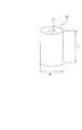
図1は、本実施の形態におけるフェライト磁石の概略を説明するための図である。
図1に示すように、フェライト磁石10は、外形円筒状で、その中央部には軸線方向に伸びる孔11が形成されて、リング状の断面を有している。このフェライト磁石10は、高さ方向の寸法(L)と外径(R)との比(L/R)が2.0以上とされている。
このようなフェライト磁石10は、孔11に図示しない回転シャフトが挿入・固定されることで、洗濯機、皿洗い機等のウォーターポンプ用のモータに組み込まれるマグネットを構成する。
Hereinafter, the present invention will be described in detail based on embodiments shown in the accompanying drawings.
FIG. 1 is a diagram for explaining the outline of a ferrite magnet in the present embodiment.
As shown in FIG. 1, the
Such a
このようなフェライト磁石10は、六方晶構造を有するフェライトを主相とし、Sr、Ba、CaおよびPbから選択される少なくとも1種の元素であって、Srを必ず含むものをAとし、希土類元素(Yを含む)およびBiから選択される少なくとも1種の元素であって、Laを必須とするものをRとし、Co、またはCoおよびZnをMとしたとき、A、R、FeおよびMを含有し、
式(1) A1−xRx(Fe12−yMy)zO19(x、y、zはモル数)
と表したとき、
0.04≦x≦0.5
0.04≦y≦0.5
0.7 ≦z≦1.2
1≦(x/y)
であるものとするのが好ましい。
Such a
Equation (1) A 1-x R x (Fe 12-y M y) z O 19 (x, y, z is the number of moles)
When
0.04 ≦ x ≦ 0.5
0.04 ≦ y ≦ 0.5
0.7 ≦ z ≦ 1.2
1 ≦ (x / y)
It is preferable that
さて、このようなフェライト磁石10は、以下のような工程を経て製造される。
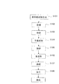
図2は、本実施の形態におけるフェライト磁石の製造工程の流れの一例を示す図である。なお、本実施の形態で示すフェライト磁石の製造工程はあくまでも一例に過ぎず、適宜変更を加えることが可能なのは言うまでも無い。
Now, such a
FIG. 2 is a diagram showing an example of the flow of the manufacturing process of the ferrite magnet in the present embodiment. In addition, it cannot be overemphasized that the manufacturing process of the ferrite magnet shown in this Embodiment is only an example, and can change suitably.
(原料組成物生成工程)
この図2に示すように、フェライト磁石を製造するには、まず原料粉末を所定の配合比で混合する(ステップS101)。原料粉末としては、例えば、Fe2O3粉末、SrCO3粉末、SiO2粉末、CaCO3粉末を用いる。FeとSrが所定の比率(モル比)になるようにFe2O3粉末およびSrCO3粉末を秤量し、さらにこの混合物に対してSiO2粉末、CaCO3粉末を所定量添加して原料組成物を得る。
(Raw material composition production process)
As shown in FIG. 2, to manufacture a ferrite magnet, first, raw material powders are mixed at a predetermined blending ratio (step S101). As the raw material powder, for example, Fe 2 O 3 powder, SrCO 3 powder, SiO 2 powder, and CaCO 3 powder are used. Fe 2 O 3 powder and SrCO 3 powder are weighed so that Fe and Sr have a predetermined ratio (molar ratio), and then a predetermined amount of SiO 2 powder and CaCO 3 powder are added to this mixture to obtain a raw material composition Get.
(仮焼工程)
得られた原料組成物を、アトライタ等で所定時間湿式混合し、造粒して、乾燥させた後に、所定温度で所定時間の仮焼を行うことで、仮焼体を得る(ステップS102)。
(Calcination process)
The obtained raw material composition is wet-mixed with an attritor or the like for a predetermined time, granulated and dried, and then calcined at a predetermined temperature for a predetermined time to obtain a calcined body (step S102).
(粉砕工程)
次いで、得られた仮焼体を粗粉砕工程、微粉砕工程を経ることでサブミクロンサイズまで粉砕し(ステップS103)、フェライト粒子からなる微粉砕粉末を得る。
粗粉砕工程では、仮焼体をローラーミル等で粗粉砕する。この後、粗粉砕された仮焼体に、磁気特性を向上させるための添加剤として、例えば、Fe2O3粉末、La(OH)3粉末、Co3O4粉末、SiO2粉末、CaCO3粉末を添加し、アトライタ等で微粉砕を行う。なお、微粉砕には分散媒として水等を用いることができる。
この後、微粉砕スラリーを脱水することにより固形分濃度を調整し、これを乾燥する。得られた乾燥粉に対して、SiO2、ステアリン酸カルシウム、昇華性バインダ(カンファ)等を添加し、これらを混合した後に、ハンマーミル等を使用して混合粉末を解砕する。
(Crushing process)
Next, the obtained calcined body is pulverized to a submicron size through a coarse pulverization step and a fine pulverization step (step S103) to obtain a fine pulverized powder composed of ferrite particles.
In the coarse pulverization step, the calcined body is coarsely pulverized with a roller mill or the like. Thereafter, as an additive for improving the magnetic characteristics of the coarsely pulverized calcined body, for example, Fe 2 O 3 powder, La (OH) 3 powder, Co 3 O 4 powder, SiO 2 powder, CaCO 3 Add powder and pulverize with an attritor. Note that water or the like can be used as a dispersion medium for the fine pulverization.
Thereafter, the solid content concentration is adjusted by dehydrating the finely pulverized slurry and dried. To the obtained dry powder, SiO 2 , calcium stearate, sublimation binder (camphor) and the like are added, and after mixing these, the mixed powder is crushed using a hammer mill or the like.
(予備成形工程)
そして、解砕した粉末を、所定の磁場を印加しつつ予備成形する。このとき、印加する磁場は、加圧方向と平行な方向とし、いわゆる縦磁場成形とする(ステップS104)。
このとき、予備成形により得られる予備成形体は、例えば円柱状とし、その成形体密度を、理論密度の51%を超え、57%以下となるようにするのが好ましい。
(Preliminary molding process)
Then, the pulverized powder is preformed while applying a predetermined magnetic field. At this time, the magnetic field to be applied is a direction parallel to the pressurizing direction, so-called longitudinal magnetic field shaping (step S104).
At this time, it is preferable that the preformed body obtained by the preforming is, for example, cylindrical, and the density of the molded body is more than 51% of the theoretical density and not more than 57%.
(解砕工程)
得られた予備成形体を、解砕し、磁場顆粒材を得る(ステップS105)。このとき、解砕後に得られる磁場顆粒材の平均粒径が0.1mm以上0.4mm未満となるように解砕するのが好ましい。これには、メッシュサイズが#40を超え#70以下のスクリーンメッシュに、予備成形体を通すことで解砕を行うのが好ましい。さらに好ましくは、メッシュサイズが#50〜#70のスクリーンメッシュに予備成形体を通すことで解砕を行う。
(Crushing process)
The obtained preform is crushed to obtain a magnetic granule (step S105). At this time, it is preferable to crush so that the average particle diameter of the magnetic field granule material obtained after crushing may be 0.1 mm or more and less than 0.4 mm. For this purpose, it is preferable to perform crushing by passing the preform through a screen mesh having a mesh
(本成形工程)
この磁場顆粒材を用いて磁場中成形を行い、リング状の成形体を得る(ステップS106)。このとき、得られる成形体の密度は、理論密度の52〜56%となるようにするのが好ましい。
磁場中成形では、加圧方向と垂直な方向とした、いわゆる横磁場成形とし、所定の強度の磁場を印加する。
(Main molding process)
Using this magnetic granule material, molding is performed in a magnetic field to obtain a ring-shaped molded body (step S106). At this time, the density of the obtained molded body is preferably 52 to 56% of the theoretical density.
In the magnetic field forming, so-called transverse magnetic field forming in a direction perpendicular to the pressing direction is applied, and a magnetic field having a predetermined strength is applied.
(焼成工程、加工工程)
このようにして作製した成形体を所定条件で焼成して焼結体を得る(ステップS107)。次いで焼結体を所定寸法に加工することで、フェライト磁石が得られる(ステップS108)。
(Baking process, processing process)
The molded body thus produced is fired under predetermined conditions to obtain a sintered body (step S107). Next, the sintered body is processed into a predetermined dimension, whereby a ferrite magnet is obtained (step S108).
さて、本発明においては、予備成形体の密度を、理論密度の51%を超え、57%以下となるようにし、この予備成形体を、平均粒径が0.1mm以上0.4mm未満となるように解砕した磁場顆粒材を用いて圧縮成形することで、フェライト磁石を得るようにした。これにより、高さ方向の寸法(L)と外径(R)との比(L/R)が2.0以上の、長尺のフェライト磁石を得ることができ、しかもその強度が高いものとなる。従来材料では、予備成形体の密度を上記のように上げると磁気特性が低下するが、本発明においては、La、Coを添加することで、磁気特性を従来と同等以上とすることができる。
このようにして、高特性・高強度のフェライト磁石を得ることができ、高トルクが作用する、洗濯機、皿洗い機等のウォーターポンプ用のモータに組み込まれるマグネットに好適である。
In the present invention, the density of the preform is over 51% of the theoretical density and 57% or less, and the preform has an average particle size of 0.1 mm or more and less than 0.4 mm. The ferrite magnet was obtained by compression molding using the pulverized magnetic field granule material. As a result, a long ferrite magnet having a ratio (L / R) of the dimension (L) in the height direction to the outer diameter (R) of 2.0 or more can be obtained, and the strength is high. Become. In the case of the conventional material, when the density of the preform is increased as described above, the magnetic characteristics are deteriorated. However, in the present invention, the magnetic characteristics can be made equal to or higher than the conventional one by adding La and Co.
Thus, a ferrite magnet having high characteristics and high strength can be obtained, and it is suitable for a magnet incorporated in a motor for a water pump such as a washing machine or a dishwasher, on which high torque acts.
原料粉末としては、例えば、Fe2O3粉末、SrCO3粉末、SiO2粉末、CaCO3粉末を用いる。これら原料粉末を、FeとSrが所定の比率(モル比)になるようにFe2O3粉末およびSrCO3粉末を秤量し、さらにこの混合物に対してSiO2粉末を0.21wt%、CaCO3粉末を0.09wt%添加して原料組成物を得た。この原料組成物をアトライタで1時間湿式混合し、乾燥して整粒した後に、1350℃で2時間仮焼を行った。 As the raw material powder, for example, Fe 2 O 3 powder, SrCO 3 powder, SiO 2 powder, and CaCO 3 powder are used. From these raw material powders, Fe 2 O 3 powder and SrCO 3 powder are weighed so that Fe and Sr have a predetermined ratio (molar ratio), and 0.21 wt% of SiO 2 powder and CaCO 3 are added to this mixture. The raw material composition was obtained by adding 0.09 wt% of the powder. This raw material composition was wet mixed with an attritor for 1 hour, dried and sized, and then calcined at 1350 ° C. for 2 hours.
仮焼体をローラーミルで粗粉砕した後に、Fe2O3粉末(平均粒径=0.3μm)、La(OH)3粉末(平均粒径=0.5μm)、Co3O4粉末(平均粒径1.0〜5.0μm)、SiO2粉末(平均粒径=0.01μm)、CaCO3粉末(平均粒径=1.0μm)を添加し、アトライタで比表面積(BET)が6.5m2/gになるように微粉砕を行った。なお、微粉砕には分散媒として水を使用した。この時のフェライト組成はSr0.792La0.208Fe11.84Co0.162O19である。また、SiO2粉末およびCaCO3粉末は、CaCO3/SiO2=1.75(モル比)、SiO2+CaCO3=1.96wt%となるように添加した。 After roughly pulverizing the calcined body with a roller mill, Fe 2 O 3 powder (average particle size = 0.3 μm), La (OH) 3 powder (average particle size = 0.5 μm), Co 3 O 4 powder (average) Particle size 1.0-5.0 μm), SiO 2 powder (average particle size = 0.01 μm), CaCO 3 powder (average particle size = 1.0 μm) were added, and the specific surface area (BET) was 6. Fine pulverization was performed so as to be 5 m 2 / g. Note that water was used as a dispersion medium for the fine pulverization. The ferrite composition at this time is Sr 0.792 La 0.208 Fe 11.84 Co 0.162 O 19 . Further, SiO 2 powder and CaCO 3 powder, CaCO 3 / SiO 2 = 1.75 ( molar ratio) was added to a SiO 2 + CaCO 3 = 1.96wt% .
微粉砕スラリーを脱水することにより固形分濃度を76wt%に調整し、これを350℃にて乾燥して水分濃度を0.3wt%以下にした。得られた乾燥粉に対して、SiO2を0.06wt%、ステアリン酸カルシウムを0.4wt%、昇華性バインダ(カンファ)を0.7wt%添加し、ヘンシェルミキサーで10分間混合した後に、ハンマーミルを使用して混合粉末を1回解砕した。この時、ハンマーミルの出口側には穴径が2mmのスクリーンを配置した。 The solid content concentration was adjusted to 76 wt% by dehydrating the finely pulverized slurry, and this was dried at 350 ° C. to reduce the water concentration to 0.3 wt% or less. After adding 0.06 wt% of SiO 2 , 0.4 wt% of calcium stearate and 0.7 wt% of sublimation binder (camphor) to the obtained dry powder, mixing with a Henschel mixer for 10 minutes, hammer mill Was used to break up the mixed powder once. At this time, a screen having a hole diameter of 2 mm was disposed on the outlet side of the hammer mill.
以上で得られた粉末を加圧と同一方向に磁場を印加し予備成形した。予備成形により、2.9、2.7、2.5g/cm3の成形体密度(それぞれ理論密度の56%、52%、49%)の予備成形体を得た(2.5g/cm3は比較例)。予備成形体の寸法はφ60mm×15mmhとした。また、予備成形時に印加した磁場は500kA/mである。 The powder obtained above was preformed by applying a magnetic field in the same direction as pressing. The preformed molded bodies 2.9,2.7,2.5g / cm 3 density (56% of each theoretical density, 52%, 49%) was obtained preform (2.5 g / cm 3 Is a comparative example). The dimensions of the preform were φ60 mm × 15 mmh. Moreover, the magnetic field applied at the time of preforming is 500 kA / m.
得られた予備成形体を#30(目開き0.532mm)、#40(目開き0.381mm)、#60(目開き0.301mm)、#70(目開き0.211mm)のスクリーンに通す解砕を行って磁場顆粒材を得た(#30、#40のスクリーンは比較例)。 The obtained preform is passed through screens of # 30 (aperture 0.532 mm), # 40 (aperture 0.381 mm), # 60 (aperture 0.301 mm), and # 70 (aperture 0.211 mm). Crushing was performed to obtain a magnetic granule (# 30 and # 40 screens are comparative examples).
この磁場顆粒材を用いて磁場中成形を行い、高さ53mmのリング状の成形体を得た。成形密度は2.75g/cm3(理論密度の53%)とした。リング状の成形体は外径が長径26mm、短径22mmの楕円状で内径は直径7.2mmの円形であった。磁場は加圧方向と垂直な方向に600kA/mの強度で印加した。 Using this magnetic granule, molding was performed in a magnetic field to obtain a ring-shaped molded body having a height of 53 mm. The molding density was 2.75 g / cm 3 (53% of the theoretical density). The ring-shaped compact had an elliptical shape with an outer diameter of 26 mm and a minor diameter of 22 mm, and an inner diameter of a circular shape with a diameter of 7.2 mm. A magnetic field was applied at a strength of 600 kA / m in a direction perpendicular to the pressing direction.
作製した成形体を1230℃で1時間焼成して焼結体を得た。次いで焼結体を外径19mm、高さ45mmに加工して磁石体を得た。 The formed body was fired at 1230 ° C. for 1 hour to obtain a sintered body. The sintered body was then processed to an outer diameter of 19 mm and a height of 45 mm to obtain a magnet body.
そしてまず、得られた磁石体を、磁化容易軸方向に730kA/mの磁場を印加して着磁した後、所定の測定用冶具とフラックスメーターを用いて総磁束量(Total Flux)を測定した。
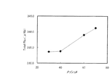
図3は、測定した結果のうち、予備成形体の密度を理論密度に対し52%とした磁石体の結果を示すものである。
この図3に示すように、予備成形体の解砕に、メッシュサイズが#40を上回るスクリーンを用いると、磁気特性(総磁束量)が向上するのが確認された。これにより、予備成形体を解砕し、磁場中成形する際の磁場顆粒材の粒径を小さくすることで、磁気特性を高めることが可能であることがわかる。
First, the obtained magnet body was magnetized by applying a magnetic field of 730 kA / m in the easy axis direction, and then the total flux was measured using a predetermined measuring jig and a flux meter. .
FIG. 3 shows the result of the magnet body in which the density of the preform is 52% of the theoretical density among the measured results.
As shown in FIG. 3, it was confirmed that when a screen having a mesh
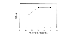
続いて、高い磁気特性を有していた、メッシュサイズが#60のスクリーンを用いて解砕した磁石体を用い、予備成形体の密度と磁石体の強度との関係を調べた。磁石体の強度を調べるには、着磁を行っていない磁石体の空隙にポリウレタン製のチューブを挿入し、治具を用いて上下方向からチューブを加圧し、磁石体の破壊強度を測定した。
図4は、その結果を示すものである。
この図4に示すように、予備成形体の密度を、理論密度に対し51%を上回るようにすることで、磁石体の破壊強度が2kN以上となり、高い強度が得られることが確認された。
さらに、メッシュサイズが#60のスクリーンを用いて解砕した磁石体について、予備成形体の密度と磁気特性の結果も図5のようにまとめた。図5に示すように、磁気特性は、予備成形体の密度を、理論密度に対し51%以上を上回るようにすると、340(μWb)を下回り、51%以下とした場合に比較すると低下する傾向にある。
Subsequently, the relationship between the density of the preform and the strength of the magnet body was examined using a magnet body that had high magnetic properties and was crushed using a screen having a mesh size of # 60. In order to examine the strength of the magnet body, a polyurethane tube was inserted into the gap of the magnet body that was not magnetized, and the tube was pressurized from above and below using a jig to measure the breaking strength of the magnet body.
FIG. 4 shows the result.
As shown in FIG. 4, it was confirmed that the fracture strength of the magnet body was 2 kN or more and a high strength was obtained by making the density of the preformed body exceed 51% of the theoretical density.
Further, the results of the density and magnetic properties of the preforms for the magnet bodies crushed using a screen having a mesh size of # 60 are summarized as shown in FIG. As shown in FIG. 5, when the density of the preform is made to exceed 51% or more of the theoretical density, the magnetic properties tend to be lower than 340 (μWb) and less than 51%. It is in.
そこで、従来材との比較を行った。ここで、本発明を適用した試料1、2、3、従来材に相当する比較試料1とも、解砕工程においては、メッシュサイズが#60のスクリーンを用いて予備成形体を解砕した。
比較試料1:フェライト組成をSrFe12O19とし、予備成形密度を2.35g/cm3(理論密度の46%)とし、顆粒化後に振動篩機を用いて造粒を行った他は、上記と同様の手法で磁石体を作製した。
試料1:予備成形密度を2.7g/cm3(理論密度の52%)とし、フェライト組成をSrFe12O19とした他は、上記と同様の手法で磁石体を作製した。
試料2:上記と同様の手法で得た、フェライト組成がSr0.792La0.208Fe11.84Co0.162O19の磁石体を用いた。ここで、予備成形体の密度を2.7g/cm3(理論密度の52%)とした。
試料3:上記と同様の手法で得た、フェライト組成がSr0.792La0.208Fe11.84Co0.162O19の磁石体を用いた。ここで、予備成形体の密度を2.9g/cm3(理論密度の56%)とした。
Therefore, a comparison with conventional materials was performed. Here, in
Comparative sample 1: SrFe 12 O 19 was used as the ferrite composition, the preforming density was 2.35 g / cm 3 (46% of the theoretical density), and granulation was performed using a vibrating sieve after granulation. A magnet body was prepared in the same manner as described above.
Sample 1: A magnet body was prepared in the same manner as described above except that the preforming density was 2.7 g / cm 3 (52% of the theoretical density) and the ferrite composition was SrFe 12 O 19 .
Sample 2: A magnet body having a ferrite composition of Sr 0.792 La 0.208 Fe 11.84 Co 0.162 O 19 obtained by the same method as described above was used. Here, the density of the preform was 2.7 g / cm 3 (52% of the theoretical density).
Sample 3: A magnet body having a ferrite composition of Sr 0.792 La 0.208 Fe 11.84 Co 0.162 O 19 obtained by the same method as described above was used. Here, the density of the preform was 2.9 g / cm 3 (56% of the theoretical density).
そして、作製した試料1、2、3、比較試料1について、磁気特性および強度を、上記と同様にして測定した。
表1はその結果を示すものである。
And about the produced
Table 1 shows the results.
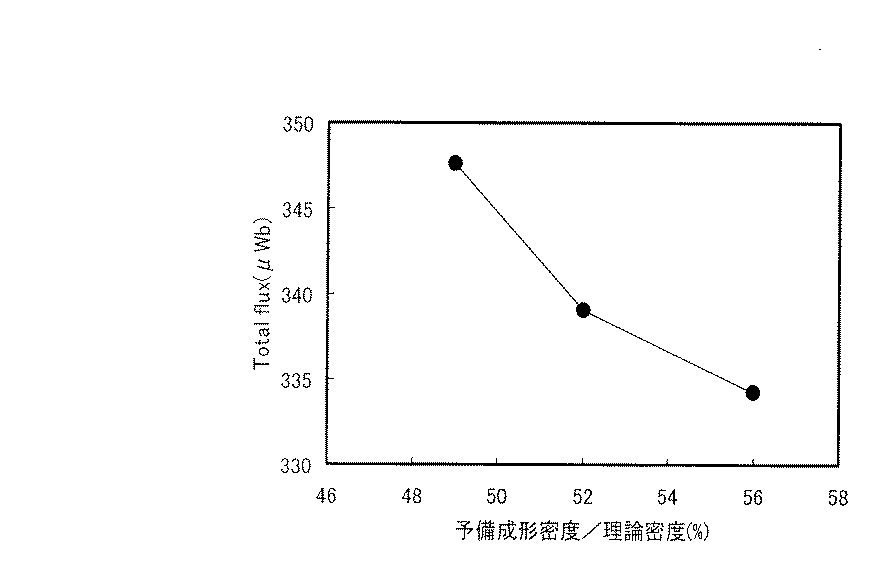
表1に示すように、特許文献1に記載された技術を適用し、予備成形体の密度を理論密度の46%とした比較試料1では、磁気特性は332.8(μWb)、強度は1.15(kN)であった。
これに対し、フェライト組成を比較試料1と同じくし、予備成形密度を本発明の範疇である理論密度の52%に向上させた試料1では、強度が2.25(kN)となり、比較試料1に比較し、著しく向上していることが確認された。しかし、磁気特性については、320.3(μWb)となり、特許文献1にも記載されているように、予備成形密度を高めることで磁気特性が低下してしまっていることが確認された。
試料2、3は、図4および図5に示した結果と同様、磁気特性が334(μWb)以上、強度が2.5(kN)以上となり、磁気特性は比較試料1の同等以上、強度は大幅に向上した。予備成形密度を等しくした試料1、2を比較すると、La、Coを添加することで、磁気特性が向上することが確認できた。また、試料2、3を比較すると、La、Coを添加した場合も、予備成形体の密度の理論密度に対する割合が高まると、磁気特性が低下する傾向にあることも確認されたが、それでも磁気特性、強度ともに、比較試料1を上回っている。
これにより、本発明によれば、特許文献1に記載された技術を適用した従来手法に比較し、予備成形密度を高めることで、強度を大幅に向上させることができることが明らかとなった。また、予備成形体の密度を上げると磁気特性が低下する傾向にあるが、La、Coを添加することで、従来手法以上に磁気特性を向上できることも確認された。
As shown in Table 1, in Comparative Sample 1 in which the technology described in Patent Document 1 was applied and the density of the preform was 46% of the theoretical density, the magnetic properties were 332.8 (μWb), and the strength was 1. .15 (kN).
On the other hand, in the case of the sample 1 in which the ferrite composition is the same as that of the comparative sample 1 and the preforming density is improved to 52% of the theoretical density which is the category of the present invention, the strength is 2.25 (kN). It was confirmed that it was remarkably improved compared to. However, the magnetic property was 320.3 (μWb), and as described in Patent Document 1, it was confirmed that the magnetic property was lowered by increasing the preforming density.
Similar to the results shown in FIGS. 4 and 5,
Thereby, according to this invention, compared with the conventional method to which the technique described in patent document 1 was applied, it became clear that intensity | strength can be improved significantly by raising a preforming density. Further, when the density of the preform is increased, the magnetic properties tend to decrease. However, it was confirmed that the addition of La and Co can improve the magnetic properties more than the conventional method.
10…フェライト磁石 10. Ferrite magnet
Claims (5)
前記予備成形体を解砕し、顆粒材を得る解砕工程と、
前記顆粒材を、磁界を印加しながら加圧成形し、本成形体を得る本成形工程と、
前記本成形体を焼成して、焼成体を得る焼成工程と、
前記焼成体を加工し、円筒状で、外径(R)とその中心軸線方向の長さ(L)との比(L/R)が2.0以上の磁石体を得る加工工程と、を備え、
前記予備成形工程では、前記予備成形体の密度が理論密度の51%を上回り、かつ57%以下となるように前記フェライト磁石材料を加圧成形することを特徴とするフェライト磁石の製造方法。 A preforming step of pressing a ferrite magnet material while applying a magnetic field to obtain a preform,
Crushing the preformed body to obtain a granule; and
The granule is pressure-molded while applying a magnetic field, and a main molding step for obtaining a main molded body,
A firing step of firing the main body to obtain a fired body,
A processing step of processing the fired body to obtain a magnet body having a cylindrical shape and a ratio (L / R) of the outer diameter (R) to the length (L) in the central axis direction of 2.0 or more. Prepared,
In the preforming step, the ferrite magnet material is pressure-molded so that the density of the preform is more than 51% of the theoretical density and not more than 57%.
式(1) A1−xRx(Fe12−yMy)zO19 (ただし、AはSr、Ba、CaおよびPbから選択され、Srを必須とする少なくとも1種の元素、Rは希土類元素(Yを含む)およびBiから選択され、Laを必須とする少なくとも1種の元素、MはCo、またはCoおよびZn、x、y、zはモル数)で表され、
0.04≦x≦0.5
0.04≦y≦0.5
0.7 ≦z≦1.2
1≦(x/y)
であることを特徴とする請求項1から4のいずれかに記載のフェライト磁石の製造方法。 The magnet body is mainly composed of ferrite having a hexagonal crystal structure,
Formula (1) A 1-x R x (Fe 12-y M y ) z O 19 (where A is selected from Sr, Ba, Ca and Pb, and at least one element in which Sr is essential, R is At least one element selected from rare earth elements (including Y) and Bi and requiring La, M is represented by Co, or Co and Zn, x, y, and z are in moles);
0.04 ≦ x ≦ 0.5
0.04 ≦ y ≦ 0.5
0.7 ≦ z ≦ 1.2
1 ≦ (x / y)
The method for producing a ferrite magnet according to any one of claims 1 to 4, wherein:
Priority Applications (1)
| Application Number | Priority Date | Filing Date | Title |
|---|---|---|---|
| JP2004103416A JP2005294330A (en) | 2004-03-31 | 2004-03-31 | Method of manufacturing ferrite magnet |
Applications Claiming Priority (1)
| Application Number | Priority Date | Filing Date | Title |
|---|---|---|---|
| JP2004103416A JP2005294330A (en) | 2004-03-31 | 2004-03-31 | Method of manufacturing ferrite magnet |
Publications (1)
| Publication Number | Publication Date |
|---|---|
| JP2005294330A true JP2005294330A (en) | 2005-10-20 |
Family
ID=35326968
Family Applications (1)
| Application Number | Title | Priority Date | Filing Date |
|---|---|---|---|
| JP2004103416A Pending JP2005294330A (en) | 2004-03-31 | 2004-03-31 | Method of manufacturing ferrite magnet |
Country Status (1)
| Country | Link |
|---|---|
| JP (1) | JP2005294330A (en) |
Cited By (8)
| Publication number | Priority date | Publication date | Assignee | Title |
|---|---|---|---|---|
| EP1798211A1 (en) * | 2005-12-19 | 2007-06-20 | TDK Corporation | Ferrite magnetic material |
| JP2007191374A (en) * | 2006-01-23 | 2007-08-02 | Tdk Corp | Method for producing ferrite magnetic material |
| JP2008160052A (en) * | 2006-03-30 | 2008-07-10 | Tdk Corp | Method of manufacturing ferrite magnet |
| JP2008270785A (en) * | 2007-03-26 | 2008-11-06 | Tdk Corp | Manufacturing method of sintered ferrite magnet |
| JP2009001476A (en) * | 2007-03-28 | 2009-01-08 | Hitachi Metals Ltd | Ferrite sintered magnet, method for producing the same and magnet roll and non-reciprocal circuit element using the same |
| CN103646770A (en) * | 2013-08-29 | 2014-03-19 | 上海晶鑫电工设备有限公司 | Rectangular iron core pressing and stacking device for electric reactor |
| CN110156452A (en) * | 2019-05-28 | 2019-08-23 | 横店集团东磁股份有限公司 | A kind of M-type strontium ferrite and preparation method thereof |
| CN110608608A (en) * | 2019-10-08 | 2019-12-24 | 海宁凌通磁业科技有限公司 | Sintering production line for ferrite |
-
2004
- 2004-03-31 JP JP2004103416A patent/JP2005294330A/en active Pending
Cited By (11)
| Publication number | Priority date | Publication date | Assignee | Title |
|---|---|---|---|---|
| EP1798211A1 (en) * | 2005-12-19 | 2007-06-20 | TDK Corporation | Ferrite magnetic material |
| US7919007B2 (en) | 2005-12-19 | 2011-04-05 | Tdk Corporation | Ferrite magnetic material |
| JP2007191374A (en) * | 2006-01-23 | 2007-08-02 | Tdk Corp | Method for producing ferrite magnetic material |
| JP2008160052A (en) * | 2006-03-30 | 2008-07-10 | Tdk Corp | Method of manufacturing ferrite magnet |
| JP2008270785A (en) * | 2007-03-26 | 2008-11-06 | Tdk Corp | Manufacturing method of sintered ferrite magnet |
| JP2009001476A (en) * | 2007-03-28 | 2009-01-08 | Hitachi Metals Ltd | Ferrite sintered magnet, method for producing the same and magnet roll and non-reciprocal circuit element using the same |
| CN103646770A (en) * | 2013-08-29 | 2014-03-19 | 上海晶鑫电工设备有限公司 | Rectangular iron core pressing and stacking device for electric reactor |
| CN110156452A (en) * | 2019-05-28 | 2019-08-23 | 横店集团东磁股份有限公司 | A kind of M-type strontium ferrite and preparation method thereof |
| CN110156452B (en) * | 2019-05-28 | 2020-12-22 | 横店集团东磁股份有限公司 | M-type strontium ferrite and preparation method thereof |
| CN110608608A (en) * | 2019-10-08 | 2019-12-24 | 海宁凌通磁业科技有限公司 | Sintering production line for ferrite |
| CN110608608B (en) * | 2019-10-08 | 2024-02-20 | 海宁凌通磁业科技有限公司 | Sintering production line for ferrite |
Similar Documents
| Publication | Publication Date | Title |
|---|---|---|
| CN101316803B (en) | Oxide based magnetic material, process for producing the same, sintered ferrite magnet and process for producing the same | |
| KR102360147B1 (en) | Magnesium oxide-containing spinel powder and manufacturing method thereof | |
| JP6947490B2 (en) | Ferrite powder for bonded magnets, their manufacturing methods, and ferrite-based bonded magnets | |
| JP5358998B2 (en) | Manufacturing method of sintered ferrite magnet | |
| KR20080037521A (en) | Hexagonal Jet Ferrite Sintered Body and Manufacturing Method Thereof | |
| JP4821792B2 (en) | Manufacturing method of sintered ferrite magnet | |
| JP6797735B2 (en) | Ferrite powder for bonded magnets and its manufacturing method | |
| JP4877514B2 (en) | Manufacturing method of sintered ferrite magnet | |
| US6755988B1 (en) | Method for making ferrite magnets | |
| JP7347296B2 (en) | Ferrite sintered magnets and rotating electrical machines | |
| JP4753054B2 (en) | Manufacturing method of sintered ferrite magnet | |
| JP2708160B2 (en) | Ferrite manufacturing method | |
| CN1561316A (en) | Ferrite type magnet manufacturing method | |
| JPH0927430A (en) | Manufacturing method of ferrite magnet | |
| JP7636106B2 (en) | Sintered ferrite magnets and rotating electrical machines | |
| JP2003257725A (en) | Oxide magnetic material, its manufacturing method, core forming method, magnetic component and coil component | |
| JP4400710B2 (en) | Ferrite magnet manufacturing method | |
| JP2001274010A (en) | Polar anisotropic cylindrical ferrite magnet and magnetic field granules | |
| JP2009027032A (en) | Manufacturing method of ferrite sintered magnet | |
| CN113436822A (en) | Ferrite sintered magnet | |
| JP2021150620A (en) | Ferrite sintered magnet | |
| JPH10265260A (en) | Method for producing calcined ferrite powder and method for producing ferrite magnet using the same | |
| JP7773329B2 (en) | Hexagonal ferrite magnetic powder for bonded magnets and its manufacturing method, and bonded magnets and its manufacturing method | |
| CN116190032B (en) | Anisotropic dry-pressed ferrite multipole magnetic ring and its preparation method | |
| JPH09312211A (en) | Oxide permanent magnet and manufacture thereof |
Legal Events
| Date | Code | Title | Description |
|---|---|---|---|
| A621 | Written request for application examination |
Free format text: JAPANESE INTERMEDIATE CODE: A621 Effective date: 20061227 |
|
| A977 | Report on retrieval |
Free format text: JAPANESE INTERMEDIATE CODE: A971007 Effective date: 20090611 |
|
| A131 | Notification of reasons for refusal |
Free format text: JAPANESE INTERMEDIATE CODE: A131 Effective date: 20090617 |
|
| A02 | Decision of refusal |
Free format text: JAPANESE INTERMEDIATE CODE: A02 Effective date: 20091014 |