JP2005294847A - Light and series light - Google Patents
Light and series light Download PDFInfo
- Publication number
- JP2005294847A JP2005294847A JP2005106359A JP2005106359A JP2005294847A JP 2005294847 A JP2005294847 A JP 2005294847A JP 2005106359 A JP2005106359 A JP 2005106359A JP 2005106359 A JP2005106359 A JP 2005106359A JP 2005294847 A JP2005294847 A JP 2005294847A
- Authority
- JP
- Japan
- Prior art keywords
- light
- emitting diode
- varistor
- diode
- light emitting
- Prior art date
- Legal status (The legal status is an assumption and is not a legal conclusion. Google has not performed a legal analysis and makes no representation as to the accuracy of the status listed.)
- Pending
Links
Images








Classifications
-
- H—ELECTRICITY
- H05—ELECTRIC TECHNIQUES NOT OTHERWISE PROVIDED FOR
- H05B—ELECTRIC HEATING; ELECTRIC LIGHT SOURCES NOT OTHERWISE PROVIDED FOR; CIRCUIT ARRANGEMENTS FOR ELECTRIC LIGHT SOURCES, IN GENERAL
- H05B47/00—Circuit arrangements for operating light sources in general, i.e. where the type of light source is not relevant
- H05B47/20—Responsive to malfunctions or to light source life; for protection
- H05B47/23—Responsive to malfunctions or to light source life; for protection of two or more light sources connected in series
-
- H—ELECTRICITY
- H05—ELECTRIC TECHNIQUES NOT OTHERWISE PROVIDED FOR
- H05B—ELECTRIC HEATING; ELECTRIC LIGHT SOURCES NOT OTHERWISE PROVIDED FOR; CIRCUIT ARRANGEMENTS FOR ELECTRIC LIGHT SOURCES, IN GENERAL
- H05B45/00—Circuit arrangements for operating light-emitting diodes [LED]
- H05B45/50—Circuit arrangements for operating light-emitting diodes [LED] responsive to malfunctions or undesirable behaviour of LEDs; responsive to LED life; Protective circuits
- H05B45/54—Circuit arrangements for operating light-emitting diodes [LED] responsive to malfunctions or undesirable behaviour of LEDs; responsive to LED life; Protective circuits in a series array of LEDs
Landscapes
- Circuit Arrangement For Electric Light Sources In General (AREA)
- Led Device Packages (AREA)
- Led Devices (AREA)
- Non-Portable Lighting Devices Or Systems Thereof (AREA)
- Illuminated Signs And Luminous Advertising (AREA)
Abstract
【課題】 設置する時に極性を考慮する必要がなく、設置、交換が便利なライトを提供する。
【解決手段】 ライトは、発光ダイオードから構成されたライトであり、発光ダイオードの両端にはバリスタを設置する。これにより、発光ダイオードとバリスタから構成された装飾用ライトは交流電源に対して無極性ライトになり、交流電源内の一周期電圧内で常に半波発光する。この種の装飾用ライトを使用した直列ライトは、一本の電線上に繋いだ発光ダイオードが全て正負極性を考慮する必要がなく、仮に発光ダイオードが焼き切れても、この発光ダイオードに接続したバリスタは通電し続け、同一電線上のその他の発光ダイオードは通電発光する。発光ダイオードが点滅しても壊れにくく、使用寿命が長い。更に設置時に極性を考慮する必要がなく、設置、交換が便利である。更に装飾用ライトは分圧抵抗を具え、電圧又は電流の瞬間衝撃を受ける。
【選択図】 図1PROBLEM TO BE SOLVED: To provide a light that is convenient to install and replace without having to consider polarity when installing.
The light is a light composed of light emitting diodes, and varistors are installed at both ends of the light emitting diodes. As a result, the decorative light composed of the light emitting diode and the varistor becomes a nonpolar light with respect to the AC power supply, and always emits half-wave light within one cycle voltage in the AC power supply. Series lights using this type of decorative light do not need to consider the positive and negative polarity of all the light-emitting diodes connected on a single electric wire. Continues to be energized, and other light emitting diodes on the same wire emit light. Even if the light emitting diode blinks, it is hard to break and has a long service life. Furthermore, there is no need to consider the polarity during installation, and installation and replacement are convenient. Furthermore, the decorative light has a voltage dividing resistance and is subjected to an instantaneous shock of voltage or current.
[Selection] Figure 1
Description
本発明は、照明技術、特にライト及び直列ライトに関するものである。 The present invention relates to lighting technology, in particular to lights and series lights.
現在の白熱灯は、発光輝度が限られており、電圧も低く、一般に数ボルトの交流電圧である。その構造は、ガラス電球の中にタングステン線が設置され、白熱灯は消費電力が大きい上に、タングステン線は焼き切れやすい。特に電圧箇所が通電、切断の状態であったり、明りの箇所が点滅状態である場合、更に焼き切れやすくなる。ライトを繋いで直列ライトにした時、そのうちのライトの一つ、もしくは幾つかのライトが壊れた場合、その直列ライトの回路は温度が上昇し、電球は更に明るくなり、電線が熱くなって火事の危険がある。発光ダイオードは低圧駆動、省電力、壊れにくい等の特性を具えることから、発光ダイオードの照明器具は抗振動、省電力、発熱しない、環境に優しい等の長所を具え、現在、発光ダイオードは白熱灯に取って代わりつつある。発光ダイオードは単方向誘導性を具え、交流電気の正半周に発光ダイオードの正負極が加わると、発光ダイオードは通電して発光する。また、交流電気の逆半周に発光ダイオードの正負極が加わると、発光ダイオードが消える。これによって交流電源は一周期内で常にハーフ周波発光する。一般交流電気の周波数は50Hzから60Hzである。このように発光ダイオードが消える時間は僅か0.01秒で人の目では発光ダイオードはずっと発光しているように見える。しかし、発光ダイオードの単方向誘導性は直列全ての発光ダイオードが同方向で電源の電線上に繋がり、ようやく電線全てに通電し、発光ダイオードが発光する。もし反対接続もしくは損傷した場合、その電線のライトは全て発光しない。直列ライトの電線は、交織結合構造で、製造もしくはメンテナンスの時、ライトを一本の線上に前後が隣り合うライトが交織されるが、この時、どれが前でどれが後かを判別しにくい。発光ダイオードを電線上に繋げるには、交織されて一緒になっている電線を分け、前後を正確に繋げなければならない。これは電線の交織構造に影響を与えるだけでなく、作業量が大きくなり、操作が不便である。 Current incandescent lamps have limited emission brightness, low voltage, and are generally several volts AC voltage. The structure is such that a tungsten wire is installed in a glass bulb, the incandescent lamp consumes a large amount of power, and the tungsten wire is easy to burn out. In particular, when the voltage portion is energized and disconnected, or when the light portion is blinking, it becomes easier to burn out. When connecting lights into a series light, if one or several of the lights break, the series light circuit will rise in temperature, the bulbs will become brighter, the wires will heat up and the fire There is a danger of. Since light emitting diodes have characteristics such as low voltage drive, power saving, and resistance to breakage, light emitting diode lighting fixtures have advantages such as anti-vibration, power saving, no heat generation, and environmental friendliness. Currently, light emitting diodes are incandescent. It is replacing the light. The light emitting diode is unidirectionally inductive, and when the positive and negative electrodes of the light emitting diode are added to the positive and negative circumferences of AC electricity, the light emitting diode emits light when energized. Further, when the positive and negative electrodes of the light emitting diode are added to the reverse half of AC electricity, the light emitting diode disappears. As a result, the AC power supply always emits half-frequency light within one cycle. The frequency of general AC electricity is 50 Hz to 60 Hz. In this way, the light-emitting diode disappears for only 0.01 seconds, and it seems that the light-emitting diode is continuously emitting light to the human eye. However, the unidirectional inductivity of the light-emitting diode is such that all light-emitting diodes in series are connected to the power supply wires in the same direction, and finally all the wires are energized and the light-emitting diodes emit light. If the connection is reversed or damaged, all the lights on the wire will not emit light. The electric wire of the series light has an union structure, and at the time of manufacturing or maintenance, it is difficult to distinguish which light is front and which is behind after light is woven on one line. . In order to connect a light emitting diode on an electric wire, it is necessary to divide the electric wires that are interwoven together and connect them accurately. This not only affects the union structure of the electric wires, but also increases the amount of work and is inconvenient to operate.
本発明の解決しようとする問題点は、製造、設置の時に方向性を考慮しなければならないため、作業効率が上がらない上、作業強度が高い点である。 The problem to be solved by the present invention is that work efficiency is not increased and work strength is high because directionality must be taken into consideration during manufacture and installation.
本発明は、発光ダイオードから構成されたライト及び直列ライトで、発光ダイオードの両端にはバリスタを設置する。これによって、発光ダイオードとバリスタから構成された装飾用ライトは交流電源に対して無極性ライトになり、交流電源内の一周期電圧内で、常に半波発光する。この種の装飾用ライトを使用した直列ライトは、一本の電線上に繋いだ発光ダイオードが全て正負極性を考慮する必要がなく、且つ仮に発光ダイオードが焼き切れても、この発光ダイオードに接続したバリスタは通電し続け、同一電線上のその他の発光ダイオードは通電発光する。発光ダイオードが点滅しても壊れにくく、使用寿命が長い。更に設置する時に極性を考慮する必要がなく、設置、交換が便利である。更に装飾用ライトには分圧抵抗を具え、電圧もしくは電流の瞬間衝撃を受けることを最も主要な特徴とする。 The present invention is a light composed of light emitting diodes and a series light, and varistors are installed at both ends of the light emitting diodes. As a result, the decorative light composed of the light emitting diode and the varistor becomes a nonpolar light with respect to the AC power supply, and always emits half-wave light within one cycle voltage in the AC power supply. A series light using this type of decorative light does not need to consider all the light-emitting diodes connected on a single electric wire, and even if the light-emitting diodes burn out, they are connected to this light-emitting diode. The varistor continues to be energized, and the other light emitting diodes on the same wire emit energized light. Even if the light emitting diode blinks, it is hard to break and has a long service life. Furthermore, there is no need to consider polarity when installing, and installation and replacement are convenient. In addition, the decorative light has a voltage dividing resistance, and the most important feature is that it receives an instantaneous shock of voltage or current.
本発明のライト及び直列ライトは、使用寿命が長く、交流電気の時、電源の方向性を考慮する必要がなく、電源の正半周もしくは負半周に関わらず、電流が通過するという利点がある。
更に、使用寿命が長く、交流電気の時、ライトの方向一致を考慮する必要がなく、交流電気の正半周もしくは負半周に関わりなく、各ライトは電流が通過し、設置、メンテナンスが容易であるという利点がある。
The light and the series light of the present invention have a long service life, and there is an advantage that current does not need to be taken into consideration in the case of AC electricity, and the current passes regardless of the positive or negative half of the power supply.
Furthermore, it has a long service life, and it is not necessary to consider the light direction coincidence when using AC electricity. Regardless of the positive or negative half of the AC electricity, each light passes current and is easy to install and maintain. There is an advantage.
本発明のライトは、照明灯、探査灯、またはクリスマスライト等の装飾用ライトに応用可能である。本発明の実施例では、装飾用ライトを例とする。図1に示すとおり、発光ダイオード1の両端にはバリスタ2が接続される。
The light of the present invention can be applied to a decoration light such as an illumination light, an exploration light, or a Christmas light. In the embodiment of the present invention, a decorative light is taken as an example. As shown in FIG. 1,
図2に示すバリスタ2は、発光ダイオード1と反方向で接続した整流ダイオードDである。装飾用ライトを交流電源上に接続し、交流電源の正半周に発光ダイオード1の正負極を加えた場合、発光ダイオード1は通電して発光し、整流ダイオードDで止まる。交流電源の負半周に発光ダイオード1の正負極を加えた場合、発光ダイオード1は光が消え、整流ダイオードDに通電する。電流は装飾用ライトを通過することが出来るので、この装飾用ライトに加わった電圧はハーフ周波で発光ダイオード1に通電して発光する。また、ハーフ周波が整流ダイオードDを通過して通電し、一つの交流電気で発光ダイオード1と整流ダイオードDが組み合わさった装飾用ライトに常に電流が通過する。
The
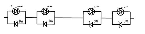
図3に示すバリスタ2は、発光ダイオード1と反方向で接続した定電圧ダイオードDWである。装飾用ライトを交流電源上に接続し、交流電源の正半周に発光ダイオード1の正負極を加えた場合、発光ダイオード1は通電して発光し、定電圧ダイオードDWで止まる。交流電源の負半周に発光ダイオード1の正負極を加えた場合、発光ダイオード1は光が消え、定電圧ダイオードDWに通電する。電流は装飾用ライトを通過することが出来るので、この装飾用ライトに加わった電圧はハーフ周波で発光ダイオード1に通電して発光する。また、ハーフ周波が定電圧ダイオードDWを通過して通電し、一つの交流電気で発光ダイオード1と定電圧ダイオードDWが組み合わさった装飾用ライトに常に電流が通過する。
The
図4に示すバリスタ2は、発光ダイオード1と反方向で接続したツェナダイオードZDである。装飾用ライトを交流電源上に接続し、交流電源の正半周に発光ダイオード1の正負極を加えた場合、発光ダイオード1は通電して発光し、ツェナダイオードZDで止まる。交流電源の負半周に発光ダイオード1の正負極を加えた場合、発光ダイオード1は光が消え、ツェナダイオードZDに通電する。電流は装飾用ライトを通過することが出来るので、この装飾用ライトに加わった電圧はハーフ周波で発光ダイオード1に通電して発光する。また、ハーフ周波がツェナダイオードZDを通過して通電し、一つの交流電気で発光ダイオード1とツェナダイオードZDが組み合わさった装飾用ライトに常に電流が通過する。
The
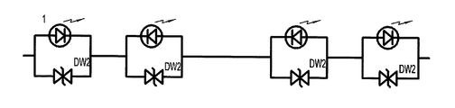
図5に示すバリスタ2は、発光ダイオード1の両端に接続する双方向定電圧ダイオードDW2である。装飾用ライトを交流電気に接続し、交流電源の正半周に発光ダイオード1の正負極を加えた場合、発光ダイオード1は通電して発光する。交流電源の負半周に発光ダイオード1の正負極を加えた場合、発光ダイオード1は光が消え、双方向定電圧ダイオードDW2を突き抜け、電流は双方向定電圧ダイオードDW2を通過する。この装飾用ライトに加わった電圧はハーフ周波で発光ダイオード1に通電して発光する。また、ハーフ周波が双方向定電圧ダイオードDW2を通過して通電し、一つの交流電気で発光ダイオード1と双方向定電圧ダイオードDW2が組み合わさった装飾用ライトが常に通電する。
The
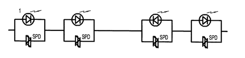
図6に示すバリスタ2は、発光ダイオード1の両端に接続するショットキ・バリア・ダイオードSPDとする。装飾用ライトを交流電気に接続し、交流電源の正半周に発光ダイオード1の正負極を加えた場合、発光ダイオード1は通電して発光する。交流電源の負半周に発光ダイオード1の正負極を加えた場合、発光ダイオード1は光が消え、ショットキ・バリア・ダイオードSPDを突き抜け、電流はショットキ・バリア・ダイオードSPDを通過する。この装飾用ライトに加わった電圧はハーフ周波で発光ダイオード1に通電して発光する。また、ハーフ周波がショットキ・バリア・ダイオードSPDを通過して通電し、一つの交流電気で発光ダイオード1とショットキ・バリア・ダイオードSPDが組み合わさった装飾用ライトが常に通電する。
The
本発明の実施例によるライトは、図7に示すとおり、バリスタ2が発光ダイオード1の樹脂密封外体3の二本の内管脚4に接続される。
In the light according to the embodiment of the present invention, the
本発明の実施例によるライトの別種構造は図8に示すとおり、バリスタ2が発光ダイオード1の二本の外導線4´に接続される。
As shown in FIG. 8, another type of light structure according to the embodiment of the present invention has a
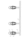
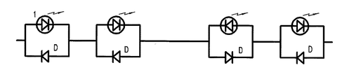
本発明の実施例による直列ライトは、装飾用ライトを例とする。図9に示すとおり、発光ダイオード1、バリスタ2、交織主電線5、交織支電線6、ライト台7、導電片8から構成される。装飾用ライトは、交流電圧の120Vの電源に接続し、60個のライト台7を繋ぐ。交織主電線5は、交織して一緒になったアース線と活線で、アース線は外向きに60本の交織支電線6が伸びる。更に交織支電線6上には分断開口が設置され、各交織支電線6は各々のライト台7に連接する。ライト台7内には二個の交織支電線6を分ける箇所と連接する導電片8が設置され、発光ダイオード1の樹脂密封外体3内の内管脚4にはバリスタ2が設置され、発光ダイオード1の二個の外導線4´は各々ライト台7内の二個の導電片8に各々挿し込まれる。この種の構造に依る装飾用直列ライトの回路は図11から図14に示すとおり、バリスタが半方向で発光ダイオード1両端に接続した整流ダイオードDもしくは定電圧ダイオードDWもしくはツェナダイオードZDであるか、またはバリスタ2が発光ダイオード1両端に接続した双方向定電圧ダイオードDW2もしくはショットキ・バリア・ダイオードSPDである。バリスタ2が発光ダイオード1の樹脂密封外体3内に設置され、発光ダイオード1とバリスタ2が組み合わさった各装飾用ライトは交流電源で無極性ライトに相当するため、連接された発光ダイオード1の極性が一致するか否かに関わらず、装飾用ライトに通電し、製造時には設置する極性を考慮する必要がなく、作業効率が上がり、労働強度が下がる。また検査時、仮に発光ダイオード1の何個かが壊れていた場合、使用者が自分で交換でき、光らなくなった発光ダイオード1を抜き、新しい発光ダイオード1を差し込めばよいだけである。発光ダイオード1内に予めバリスタ2が接続し、発光ダイオード1を接続する時、新しく差し込む発光ダイオード1両端の電圧瞬間は高くなく、発光ダイオード1は焼き切れしにくい。公知の技術である発光ダイオード1が連接された連なりは、もしもそのうちの一個が壊れた場合、壊れた発光ダイオード1を抜いた後、両端の電圧は120もしくは220Vで、新しく交換した発光ダイオード1を接続した後、壊れやすかったり、焼き切れやすかったりして、使用寿命が短かった。しかし、本発明の実施例では、バリスタ2が120もしくは20Vの電源内で良好な保護作用をするため、発光ダイオード1は壊れたり、焼ききれたりしにくく、発光ダイオード1の使用寿命を延ばす。
The serial light according to the embodiment of the present invention is exemplified by a decorative light. As shown in FIG. 9, the
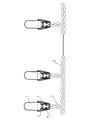
本発明の実施例による装飾用直列ライトの別種構造は、図10に示すもので、発光ダイオード1、バリスタ2、交織主電線5、交織支電線6、ライト台7、そして導電片8から構成される。交織主電線5は交織で一つになったアース線と活線で、アース線は装飾用ライトの個数に基づいて外に伸びる交織支電線6となる。更に交織支電線6上には分断開口が設置され、各交織支電線6は各々ライト台7と連接し、ライト台7内には二個の交織支電線6の分断開口点二箇所と連接する導電片8が設置される。バリスタ2にこの導電片8上に設置され、発光ダイオード1の外導線4´二本は各々ライト台7内の導電片8二個に差し込む。この種の構造の装飾用ライトは回路原理が図11から12に示す。バリスタ2は発光ダイオード1両端の双方向定電圧ダイオードDW2、もしくはショットキ・バリア・ダイオードSPDに接続される。このように発光ダイオード1と双方向定電圧ダイオードDW2、もしくはショットキ・バリア・ダイオードSPDが組み合わさった各装飾用ライトは交流電源に対して発光ダイオード1の方向性の影響を受けず、無極性ライトに相当する。そのため、直列の発光ダイオード1の極性が一致するか否かに関わらず、装飾用ライトは通電する。生産時にも同様に極性を考慮することなく設置できるので、作業効率が上がり、作業強度は下がる。更に発光ダイオード1を交換する場合、予め設置下双方向定電圧ダイオードDW2、もしくはショットキ・バリア・ダイオードSPDによって、発光ダイオード1を差し込むとき、新しく差し込む発光ダイオード1両端の電圧瞬間は高くならず、発光ダイオード1が傷ついたり、焼き切れたりしにくく、発光ダイオード1の使用寿命が延びる。
Another type of decorative series light according to an embodiment of the present invention is shown in FIG. 10, and is composed of a
1 発光ダイオード、2 バリスタ、3 樹脂密封外体、4 内管脚、4´ 外導線、 5 交織主電線、6 交織支電線、7 ライト台、D 整流ダイオード、DW 定電圧ダイオード、ZD ツェナダイオード、DW2 双方向定電圧ダイオード、SPD ショットキ・バリア・ダイオード
DESCRIPTION OF
Claims (11)
発光ダイオードと交織して一つになった交織主電線を含み、そのうち一本の交織主電線上には、分断した交織支電線が設置され、その交織支電線上にライト台が接続され、発光ダイオードの樹脂密封外体内の二個の内管脚には、前記バリスタが接続され、更にライト台内には交織支電線の分断点には二個の導電体を各々接続し、発光ダイオードの二本の外導線にはライト台内の二個の導電体を各々対応して差し込むことを特徴とする直列ライト。 A series light having the varistor according to claim 2,
It includes a union main wire that is combined with a light-emitting diode, and a single union main wire is installed on the union main wire, and a light stand is connected to the union main wire to emit light. The two varistors are connected to the two inner tube legs in the resin-sealed outer body of the diode, and two conductors are connected to the dividing points of the weaving branch wires in the light base. A serial light characterized in that two conductors in a light stand are respectively inserted into the outer conductor of the book.
発光ダイオードと交織して一つになった交織主電線を含み、そのうち一本の交織主電線上には、分断して開いた交織支電線が設置され、交織支電線上にライト台が設置され、ライト台内には、交織支電線の二つの分断点と電気連接された二個の導電体が設置され、前記バリスタが前記ライト台内に設置され、このバリスタの両端は交織支電線の二箇所の分断点と各々電気連接され、発光ダイオードの二本の外導電はライト台内の二個の導電体に差し込まれることを特徴とする直列ライト。 A serial light having a varistor according to claim 5 or 6,
It includes a union main wire that is united with a light-emitting diode, and a single union main wire is installed on the union main wire, and a light stand is installed on the union branch wire. In the light stand, two conductors electrically connected to the two breaking points of the union branch wire are installed, the varistor is installed in the light stand, and both ends of the varistor are connected to the two ends of the union branch wire. A series light characterized in that the two external conductors of the light-emitting diode are respectively inserted into two conductors in the light stand, and are electrically connected to the breaking point of the location.
Applications Claiming Priority (1)
| Application Number | Priority Date | Filing Date | Title |
|---|---|---|---|
| CNU2004200443054U CN2694702Y (en) | 2004-04-02 | 2004-04-02 | Decorative lights and decorative lighting strings |
Publications (1)
| Publication Number | Publication Date |
|---|---|
| JP2005294847A true JP2005294847A (en) | 2005-10-20 |
Family
ID=34775197
Family Applications (1)
| Application Number | Title | Priority Date | Filing Date |
|---|---|---|---|
| JP2005106359A Pending JP2005294847A (en) | 2004-04-02 | 2005-04-01 | Light and series light |
Country Status (5)
| Country | Link |
|---|---|
| US (1) | US20080130283A1 (en) |
| EP (1) | EP1605731A3 (en) |
| JP (1) | JP2005294847A (en) |
| CN (1) | CN2694702Y (en) |
| CA (1) | CA2503416A1 (en) |
Cited By (2)
| Publication number | Priority date | Publication date | Assignee | Title |
|---|---|---|---|---|
| KR100757827B1 (en) | 2006-09-29 | 2007-09-11 | 서울반도체 주식회사 | Light emitting element |
| JP2012109202A (en) * | 2010-11-15 | 2012-06-07 | Huh Sea-Kyoung | Light emitting diode lamp |
Families Citing this family (25)
| Publication number | Priority date | Publication date | Assignee | Title |
|---|---|---|---|---|
| US20100109538A1 (en) * | 2005-02-23 | 2010-05-06 | Mei-Ling Peng | Continuous current control circuit modules of series string bulbs type |
| US7535180B2 (en) * | 2005-04-04 | 2009-05-19 | Cree, Inc. | Semiconductor light emitting circuits including light emitting diodes and four layer semiconductor shunt devices |
| US20070018594A1 (en) * | 2005-06-08 | 2007-01-25 | Jlj. Inc. | Holiday light string devices |
| US7520771B2 (en) * | 2005-07-13 | 2009-04-21 | Lumination Llc | LED string light engine and devices that are illuminated by the string light engine |
| CN201007448Y (en) * | 2007-02-12 | 2008-01-16 | 邵炽良 | Single lamp control LED light string |
| US20090278463A1 (en) * | 2008-05-06 | 2009-11-12 | Tai-Ning Tang | Power interruption protection structure for led string light |
| US20100148694A1 (en) * | 2008-12-15 | 2010-06-17 | Chu-Cheng Chang | LED light string with capacitor based rectifier filter for increasing output voltage |
| US8044599B2 (en) * | 2009-02-17 | 2011-10-25 | Chu-Cheng Chang | Light string with alternate LED lamps and incandescent lamps |
| CN101493197B (en) * | 2009-03-06 | 2013-09-04 | 北京中庆微数字设备开发有限公司 | Hose lamp |
| US8007129B2 (en) * | 2009-05-22 | 2011-08-30 | Chen-Sheng Yang | LED-based christmas light string assembly with parallel-wired lighting units |
| US9713211B2 (en) | 2009-09-24 | 2017-07-18 | Cree, Inc. | Solid state lighting apparatus with controllable bypass circuits and methods of operation thereof |
| US10264637B2 (en) | 2009-09-24 | 2019-04-16 | Cree, Inc. | Solid state lighting apparatus with compensation bypass circuits and methods of operation thereof |
| US8901845B2 (en) | 2009-09-24 | 2014-12-02 | Cree, Inc. | Temperature responsive control for lighting apparatus including light emitting devices providing different chromaticities and related methods |
| US8476836B2 (en) | 2010-05-07 | 2013-07-02 | Cree, Inc. | AC driven solid state lighting apparatus with LED string including switched segments |
| JP5740115B2 (en) * | 2010-08-24 | 2015-06-24 | 楊 泰和 | LED circuit |
| US8569974B2 (en) | 2010-11-01 | 2013-10-29 | Cree, Inc. | Systems and methods for controlling solid state lighting devices and lighting apparatus incorporating such systems and/or methods |
| US9839083B2 (en) | 2011-06-03 | 2017-12-05 | Cree, Inc. | Solid state lighting apparatus and circuits including LED segments configured for targeted spectral power distribution and methods of operating the same |
| US8742671B2 (en) | 2011-07-28 | 2014-06-03 | Cree, Inc. | Solid state lighting apparatus and methods using integrated driver circuitry |
| US8823285B2 (en) | 2011-12-12 | 2014-09-02 | Cree, Inc. | Lighting devices including boost converters to control chromaticity and/or brightness and related methods |
| US8847516B2 (en) | 2011-12-12 | 2014-09-30 | Cree, Inc. | Lighting devices including current shunting responsive to LED nodes and related methods |
| CN102588788A (en) * | 2012-02-16 | 2012-07-18 | 南通恺誉照明科技有限公司 | Mains supply LED (light emitting diode) module |
| US9980356B2 (en) * | 2013-01-04 | 2018-05-22 | Cree, Inc. | Lighting fixture with integral circuit protection |
| CN103456729B (en) * | 2013-07-26 | 2016-09-21 | 利亚德光电股份有限公司 | Light emitting diode (LED) display screen |
| CN106740440B (en) * | 2017-01-13 | 2023-10-17 | 华域视觉科技(上海)有限公司 | Automobile signal lamp switching circuit |
| IT201800010788A1 (en) * | 2018-12-04 | 2020-06-04 | Fenix S R L | LAMP AND LUMINARY |
Citations (12)
| Publication number | Priority date | Publication date | Assignee | Title |
|---|---|---|---|---|
| JPS5684368U (en) * | 1979-11-29 | 1981-07-07 | ||
| JPS60183459U (en) * | 1984-05-16 | 1985-12-05 | 日本電気株式会社 | light emitting diode |
| JPS62112165U (en) * | 1986-01-07 | 1987-07-17 | ||
| JPS62178551U (en) * | 1986-04-30 | 1987-11-12 | ||
| JPH01157384U (en) * | 1988-04-20 | 1989-10-30 | ||
| JPH0368736A (en) * | 1989-08-08 | 1991-03-25 | Nippon Steel Corp | Ni-mo reduced type fe-ni series magnetic alloy having excellent hot workability and magnetic characteristics |
| JPH0371016A (en) * | 1989-08-10 | 1991-03-26 | Mitsubishi Kasei Corp | Signal calibrating device |
| JPH1116683A (en) * | 1997-06-23 | 1999-01-22 | Masanori Minato | Light emitting display |
| JPH1154803A (en) * | 1997-07-30 | 1999-02-26 | Rohm Co Ltd | Semiconductor light emitting device |
| JP2000216442A (en) * | 1999-01-22 | 2000-08-04 | Sanken Electric Co Ltd | Semiconductor light emitting device |
| JP2001015815A (en) * | 1999-04-28 | 2001-01-19 | Sanken Electric Co Ltd | Semiconductor light emitting device |
| JP2001036140A (en) * | 1999-07-16 | 2001-02-09 | Stanley Electric Co Ltd | Antistatic surface mount LED |
Family Cites Families (5)
| Publication number | Priority date | Publication date | Assignee | Title |
|---|---|---|---|---|
| US2072337A (en) * | 1936-05-05 | 1937-03-02 | Nofade Electric Corp | Safety lighting circuit |
| US20020047594A1 (en) * | 1995-06-26 | 2002-04-25 | Janning John L. | Series connected light string with filament shunting |
| US6283797B1 (en) * | 1999-07-30 | 2001-09-04 | Jeng-Shyong Wu | Structure of a lamp base |
| US6650064B2 (en) * | 2000-09-29 | 2003-11-18 | Aerospace Optics, Inc. | Fault tolerant led display design |
| US20020043943A1 (en) * | 2000-10-10 | 2002-04-18 | Menzer Randy L. | LED array primary display light sources employing dynamically switchable bypass circuitry |
-
2004
- 2004-04-02 CN CNU2004200443054U patent/CN2694702Y/en not_active Expired - Fee Related
-
2005
- 2005-04-01 US US11/096,570 patent/US20080130283A1/en not_active Abandoned
- 2005-04-01 CA CA002503416A patent/CA2503416A1/en not_active Abandoned
- 2005-04-01 JP JP2005106359A patent/JP2005294847A/en active Pending
- 2005-04-01 EP EP05007145A patent/EP1605731A3/en not_active Withdrawn
Patent Citations (12)
| Publication number | Priority date | Publication date | Assignee | Title |
|---|---|---|---|---|
| JPS5684368U (en) * | 1979-11-29 | 1981-07-07 | ||
| JPS60183459U (en) * | 1984-05-16 | 1985-12-05 | 日本電気株式会社 | light emitting diode |
| JPS62112165U (en) * | 1986-01-07 | 1987-07-17 | ||
| JPS62178551U (en) * | 1986-04-30 | 1987-11-12 | ||
| JPH01157384U (en) * | 1988-04-20 | 1989-10-30 | ||
| JPH0368736A (en) * | 1989-08-08 | 1991-03-25 | Nippon Steel Corp | Ni-mo reduced type fe-ni series magnetic alloy having excellent hot workability and magnetic characteristics |
| JPH0371016A (en) * | 1989-08-10 | 1991-03-26 | Mitsubishi Kasei Corp | Signal calibrating device |
| JPH1116683A (en) * | 1997-06-23 | 1999-01-22 | Masanori Minato | Light emitting display |
| JPH1154803A (en) * | 1997-07-30 | 1999-02-26 | Rohm Co Ltd | Semiconductor light emitting device |
| JP2000216442A (en) * | 1999-01-22 | 2000-08-04 | Sanken Electric Co Ltd | Semiconductor light emitting device |
| JP2001015815A (en) * | 1999-04-28 | 2001-01-19 | Sanken Electric Co Ltd | Semiconductor light emitting device |
| JP2001036140A (en) * | 1999-07-16 | 2001-02-09 | Stanley Electric Co Ltd | Antistatic surface mount LED |
Cited By (3)
| Publication number | Priority date | Publication date | Assignee | Title |
|---|---|---|---|---|
| KR100757827B1 (en) | 2006-09-29 | 2007-09-11 | 서울반도체 주식회사 | Light emitting element |
| JP2012109202A (en) * | 2010-11-15 | 2012-06-07 | Huh Sea-Kyoung | Light emitting diode lamp |
| US8659241B2 (en) | 2010-11-15 | 2014-02-25 | Sea-Kyoung HUH | LED lamp |
Also Published As
| Publication number | Publication date |
|---|---|
| EP1605731A3 (en) | 2009-08-19 |
| US20080130283A1 (en) | 2008-06-05 |
| CN2694702Y (en) | 2005-04-20 |
| CA2503416A1 (en) | 2005-10-02 |
| EP1605731A2 (en) | 2005-12-14 |
Similar Documents
| Publication | Publication Date | Title |
|---|---|---|
| US11950332B2 (en) | Resistive bypass for series lighting circuit | |
| EP1605731A2 (en) | LED with load connected in parallel | |
| CN100472118C (en) | LED decorative lamp string | |
| US11716080B2 (en) | Smart switch apparatus | |
| US20230098381A1 (en) | Lighting apparatus | |
| US11168870B2 (en) | Lighting apparatus | |
| US11085622B1 (en) | Lighting apparatus | |
| US11859785B2 (en) | Lighting apparatus | |
| US11262057B2 (en) | Lighting apparatus | |
| US11828423B2 (en) | Light bulb apparatus | |
| US11441763B2 (en) | Lighting apparatus | |
| KR20060045453A (en) | Light bulb and tree bulb | |
| US20210148557A1 (en) | Lighting apparatus | |
| CN105042445A (en) | Lighting equipment used for electric system | |
| CN1838847A (en) | Lights and String Lights | |
| US11415306B2 (en) | Panel light apparatus | |
| US11719426B2 (en) | Lighting apparatus | |
| US11632839B2 (en) | Lighting apparatus | |
| US11428387B2 (en) | Lighting apparatus | |
| US11598500B2 (en) | Downlight apparatus | |
| CN2216191Y (en) | Double-lamp double-stage light-control incandescent lamp | |
| CN2786416Y (en) | Superbright portable searchlight |
Legal Events
| Date | Code | Title | Description |
|---|---|---|---|
| A621 | Written request for application examination |
Free format text: JAPANESE INTERMEDIATE CODE: A621 Effective date: 20080331 |
|
| A977 | Report on retrieval |
Free format text: JAPANESE INTERMEDIATE CODE: A971007 Effective date: 20110125 |
|
| A131 | Notification of reasons for refusal |
Free format text: JAPANESE INTERMEDIATE CODE: A131 Effective date: 20110310 |
|
| A02 | Decision of refusal |
Free format text: JAPANESE INTERMEDIATE CODE: A02 Effective date: 20110802 |