JP2005295514A - Image forming apparatus and job management method - Google Patents
Image forming apparatus and job management method Download PDFInfo
- Publication number
- JP2005295514A JP2005295514A JP2005057889A JP2005057889A JP2005295514A JP 2005295514 A JP2005295514 A JP 2005295514A JP 2005057889 A JP2005057889 A JP 2005057889A JP 2005057889 A JP2005057889 A JP 2005057889A JP 2005295514 A JP2005295514 A JP 2005295514A
- Authority
- JP
- Japan
- Prior art keywords
- job
- information
- image forming
- forming apparatus
- related information
- Prior art date
- Legal status (The legal status is an assumption and is not a legal conclusion. Google has not performed a legal analysis and makes no representation as to the accuracy of the status listed.)
- Pending
Links
Images









Landscapes
- Accessory Devices And Overall Control Thereof (AREA)
- Control Or Security For Electrophotography (AREA)
- Facsimiles In General (AREA)
Abstract
【課題】 画像形成処理に好適なジョブ管理方法と、その方法を実行する画像形成装置を提供する。
【解決手段】 画像形成処理で使用されるハードウェア資源を有し、画像形成に係るジョブを実行する画像形成装置において、1つのジョブと他のジョブとの関連を示すジョブ関連情報を、ジョブごとに生成するジョブ関連情報生成手段と、ジョブ関連情報に基づき、任意のジョブと関連のあるジョブを検索するためのジョブ構造情報を作成するジョブ構造情報作成手段とを有する。
【選択図】 図22PROBLEM TO BE SOLVED: To provide a job management method suitable for image forming processing and an image forming apparatus for executing the method.
In an image forming apparatus that has hardware resources used in image forming processing and executes a job related to image formation, job related information indicating the relationship between one job and another job is displayed for each job. A job-related information generating unit that generates job structure information for searching for a job related to an arbitrary job based on the job-related information.
[Selection] FIG.
Description
本発明は、画像形成処理に係るジョブを管理するジョブ管理方法、及びその方法を実行する画像形成装置に関する。 The present invention relates to a job management method for managing a job related to image forming processing, and an image forming apparatus for executing the method.
近年、ファクシミリ、プリンタ、コピーおよびスキャナなどの各装置の機能を1つの筐体内に収納した画像形成装置が知られるようになった。この画像形成装置は、1つの筐体内に表示部、印刷部および撮像部などを設けると共に、ファクシミリ、プリンタ、コピーおよびスキャナにそれぞれ対応する4種類のアプリケーションを設け、そのアプリケーションを切り替えることより、ファクシミリ、プリンタ、コピーおよびスキャナとして動作させるものである。 In recent years, there has been known an image forming apparatus in which functions of each apparatus such as a facsimile, a printer, a copy, and a scanner are housed in one casing. In this image forming apparatus, a display unit, a printing unit, an imaging unit, and the like are provided in one casing, and four types of applications corresponding to a facsimile, a printer, a copy, and a scanner are provided. , Operate as a printer, copy and scanner.
このような画像を出力、変更、移動動作などの画像形成に係る処理は、ジョブといわれる処理単位で実行される。例えばコピーを行う場合、画像形成装置では原稿を読み取る処理と、読み取った原稿を印刷する処理が行われるため、原稿読み取りジョブと印刷のジョブが発生する。このジョブが発生しない例として、画像形成装置の設定を変更する操作を行う場合があり、このときは画像に対する処理が行われないので、ジョブは発生しない。 Processing related to image formation, such as outputting, changing, and moving images, is executed in units of processing called jobs. For example, when copying, since the image forming apparatus performs a process of reading a document and a process of printing the read document, a document reading job and a printing job are generated. As an example in which this job does not occur, there is a case where an operation for changing the setting of the image forming apparatus is performed. In this case, no processing is performed on the image, and therefore no job is generated.
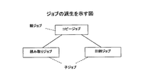
このジョブは、処理の過程でより細かいジョブとなることがある。このことを、図1を用いて説明する。例えばコピーを行う場合、画像形成装置には、まず「コピージョブ」が発生する。そして、このコピージョブから「読み取りジョブ」と「印刷ジョブ」の2つのジョブが派生する。このように1つのジョブから新たなジョブが派生した場合、前者を「親ジョブ」、後者を「子ジョブ」と呼ぶことにする。 This job may become a finer job in the course of processing. This will be described with reference to FIG. For example, when copying, a “copy job” is first generated in the image forming apparatus. Then, two jobs of “read job” and “print job” are derived from this copy job. When a new job is derived from one job in this way, the former is called “parent job” and the latter is called “child job”.
親ジョブ、子ジョブと表現すると、両者が同時に存在するようなイメージとなるが、従来では子ジョブが派生すると、親ジョブは消滅する。上の例で言えば、「読み取りジョブ」と「印刷ジョブ」が派生すると、「コピージョブ」は消滅する。従って、従来において派生するとは、親ジョブが分裂して子ジョブとなるイメージである。 When expressed as a parent job and a child job, the image is such that both exist at the same time, but conventionally, when a child job is derived, the parent job disappears. In the above example, when the “read job” and the “print job” are derived, the “copy job” disappears. Therefore, the conventional derivation is an image in which the parent job is divided into child jobs.
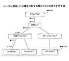
上述したコピージョブでは、1回の派生であったが、処理によってはジョブの派生が複数回行われる場合がある。例えば、図2に示されるような、カラーページと白黒ページが混在した文書を印刷する際に、カラーページと白黒ページを別のプロセスで印刷する場合を考える。 In the copy job described above, derivation is performed once. However, depending on the process, the derivation of the job may be performed a plurality of times. For example, when printing a document in which color pages and black and white pages are mixed as shown in FIG. 2, a case where color pages and black and white pages are printed by different processes is considered.
まず、画像形成装置がユーザから受けた要求により、「印刷ジョブ」が発生する。そして、印刷ジョブから「カラープリントジョブ」と「白黒プリントジョブ」が派生する。さらに、印刷を行うページ数の単位で「プロッタジョブ」が派生する。 First, a “print job” is generated in response to a request received from the user by the image forming apparatus. Then, “color print job” and “monochrome print job” are derived from the print job. Furthermore, a “plotter job” is derived in units of the number of pages to be printed.
このように派生していく様子を図にすると、図2に示されるようなジョブ構造となるが、このジョブ構造における最も根元にあるジョブを「根幹ジョブ」、末端にあるジョブを「末端ジョブ」と呼ぶ。図2の場合、根幹ジョブは、プリントジョブであり、末端ジョブは、プロッタジョブである。この根幹ジョブは、従来、スプールで処理されると消滅するようになっている。 When the state of the derivation is illustrated, the job structure as shown in FIG. 2 is obtained. The most fundamental job in this job structure is “root job”, and the end job is “end job”. Call it. In FIG. 2, the basic job is a print job, and the end job is a plotter job. Conventionally, this basic job disappears when it is processed by a spool.
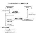
また、従来技術におけるジョブ管理では、各アプリケーション(以下、アプリケーションをアプリと表現することがある)が根幹ジョブ用のキューをそれぞれ持っており、ジョブを処理する順番を管理している。例えば、図3に示されるように、プリンタ用のアプリケーションであるプリンタアプリは、プリンタアプリ根幹ジョブ用キューで、キューに積まれた根幹ジョブA、B、Cのように、順番を管理している。 In the job management in the prior art, each application (hereinafter, the application may be referred to as an application) has a queue for a basic job, and manages the order of job processing. For example, as shown in FIG. 3, a printer application that is an application for a printer is a printer application basic job queue, and manages the order as the basic jobs A, B, and C loaded in the queue. .
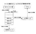
また、プロッタなどのハードウェアに対する末端ジョブも専用のキューがあり、それにより処理する順番の管理を行っている。例えば、図4に示されるように、各アプリや末端のジョブを管理するサービス層のモジュールは、プロッタジョブ用キューで、キューに積まれた末端ジョブA、B、Cのように、順番を管理する。 In addition, a terminal job for hardware such as a plotter also has a dedicated queue, which manages the processing order. For example, as shown in FIG. 4, the service layer module that manages each application and the end job is a plotter job queue, and manages the order like the end jobs A, B, and C loaded in the queue. To do.
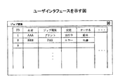
ジョブを管理するモジュールはそれらのキューにアクセスすることでジョブの情報を取得し、その情報をパソコン上のアプリに渡すことで、アプリが図5のようなユーザインタフェースを表示することができる。この表示により、ジョブの管理を行うユーザは、各ジョブの状態を見ることができる。 A module that manages jobs acquires job information by accessing these queues, and passes the information to an application on a personal computer, so that the application can display a user interface as shown in FIG. By this display, the user who manages the job can see the status of each job.
以上のように、従来は、根幹ジョブがスプールで処理されると消滅するので、ある子ジョブがどの親ジョブから派生したものか判別できない。そのため、例えば、ある末端ジョブでエラーが発生したが、それがどの要求で生じたエラーなのか判別できなかった。また、ある要求に対して発生した根幹ジョブを途中で中止しようとしても、派生した子ジョブの中止ができないため、処理が中止できないという問題点がある。 As described above, conventionally, since a basic job disappears when it is processed by spool, it cannot be determined from which parent job a certain child job is derived. Therefore, for example, an error has occurred in a certain end job, but it has not been possible to determine which request caused the error. In addition, there is a problem in that even if an attempt is made to cancel a basic job that has occurred in response to a request, the derived child job cannot be canceled, and the process cannot be canceled.
このように、従来はジョブの管理が不十分なため、ジョブに関する情報の取得や、ジョブに対する操作を十分に行うことができなかった。 Thus, conventionally, since job management is insufficient, it has been impossible to sufficiently acquire information about jobs and perform operations on jobs.
本発明は、このような問題点に鑑み、画像形成処理に好適なジョブ管理方法と、その方法を実行する画像形成装置を提供することを目的とする。 SUMMARY An advantage of some aspects of the invention is that it provides a job management method suitable for image forming processing and an image forming apparatus that executes the method.
上記課題を解決するために、本発明は、画像形成処理で使用されるハードウェア資源を有し、画像形成に係るジョブを実行する画像形成装置において、前記1つのジョブと他のジョブとの関連を示すジョブ関連情報を、前記ジョブごとに生成するジョブ関連情報生成手段と、前記ジョブ関連情報に基づき、任意のジョブと関連のあるジョブを検索するためのジョブ構造情報を作成するジョブ構造情報作成手段とを有することを特徴とする。 In order to solve the above problems, the present invention relates to a relationship between the one job and another job in an image forming apparatus that has hardware resources used in image forming processing and executes a job related to image forming. Job-related information generation means for generating job-related information for each job, and job structure information creation for creating job structure information for searching for a job related to an arbitrary job based on the job-related information Means.
また、上記課題を解決するために、本発明は、前記ジョブ関連情報は、前記ジョブの祖先にあたる全てのジョブの識別情報を含むことを特徴とする。 In order to solve the above problem, the present invention is characterized in that the job-related information includes identification information of all jobs that are ancestors of the job.
また、上記課題を解決するために、本発明は、前記ジョブ関連情報は、前記ジョブの親ジョブの識別情報を含むことを特徴とする。 In order to solve the above problem, the present invention is characterized in that the job related information includes identification information of a parent job of the job.
また、上記課題を解決するために、本発明は、前記ジョブ関連情報は、前記ジョブの子孫にあたる全てのジョブの識別情報を含むことを特徴とする。 In order to solve the above problem, the present invention is characterized in that the job-related information includes identification information of all jobs that are descendants of the job.
また、上記課題を解決するために、本発明は、前記ジョブ関連情報は、前記ジョブの子ジョブの識別情報を含むことを特徴とする。 In order to solve the above problem, the present invention is characterized in that the job related information includes identification information of a child job of the job.
また、上記課題を解決するために、本発明は、前記識別情報と前記ジョブに関する情報とを含むジョブ情報を有することを特徴とする。 In order to solve the above problem, the present invention is characterized by having job information including the identification information and information related to the job.
また、上記課題を解決するために、本発明は、前記ジョブ情報は、前記ジョブに対する操作を許可するかどうかを示すジョブ操作許可情報を含むことを特徴とする。 In order to solve the above-described problem, the present invention is characterized in that the job information includes job operation permission information indicating whether or not an operation for the job is permitted.
また、上記課題を解決するために、本発明は、前記ジョブ情報は、前記ジョブが操作可能となる条件を示すジョブ操作条件情報を含むことを特徴とする。 In order to solve the above problem, the present invention is characterized in that the job information includes job operation condition information indicating a condition under which the job can be operated.
また、上記課題を解決するために、本発明は、前記ジョブに対する操作は、前記ジョブを中止する操作であることを特徴とする。 In order to solve the above problem, the present invention is characterized in that the operation for the job is an operation for canceling the job.
また、上記課題を解決するために、本発明は、前記ジョブに対する操作は、前記ジョブを再実行する操作であることを特徴とする。 In order to solve the above problem, the present invention is characterized in that the operation for the job is an operation for re-executing the job.
また、上記課題を解決するために、本発明は、前記ジョブに対する操作は、前記ジョブを中断する操作であることを特徴とする。 In order to solve the above problem, the present invention is characterized in that the operation for the job is an operation for interrupting the job.
また、上記課題を解決するために、本発明は、前記ジョブに対する操作は、前記ジョブ情報を編集する操作であることを特徴とする。 In order to solve the above problem, the present invention is characterized in that the operation for the job is an operation for editing the job information.
また、上記課題を解決するために、本発明は、前記ジョブに対する操作は、前記ジョブを実行する機器を変更する操作であることを特徴とする。 In order to solve the above problem, the present invention is characterized in that the operation for the job is an operation for changing a device that executes the job.
また、上記課題を解決するために、本発明は、前記ジョブ情報は、各ジョブごとに作成されることを特徴とする。 In order to solve the above problem, the present invention is characterized in that the job information is created for each job.
また、上記課題を解決するために、本発明は、前記ジョブ情報を保存するとともに、前記識別情報に対応するジョブ情報を提供する記憶管理手段をさらに有することを特徴とする。 In order to solve the above problem, the present invention is characterized by further comprising storage management means for storing the job information and providing job information corresponding to the identification information.
また、上記課題を解決するために、本発明は、前記ジョブ構造情報作成手段は、前記記憶管理手段からジョブ情報を取得することにより、前記ジョブ構造情報を作成することを特徴とする。 In order to solve the above problem, the present invention is characterized in that the job structure information creating means creates the job structure information by acquiring job information from the storage management means.
また、上記課題を解決するために、本発明は、画像形成処理で使用されるハードウェア資源を有し、画像形成に係るジョブを実行する画像形成装置で、前記ジョブを管理するジョブ管理方法であって、前記ジョブのジョブ構造情報を作成するためのジョブ関連情報を生成するジョブ関連情報生成段階と、前記ジョブ関連情報に基づきジョブ構造情報を作成するジョブ構造情報作成段階とを有することを特徴とする。 In order to solve the above problems, the present invention provides a job management method for managing a job in an image forming apparatus that has a hardware resource used in image forming processing and executes a job related to image formation. A job related information generation step for generating job related information for generating job structure information for the job, and a job structure information generation step for generating job structure information based on the job related information. And
また、上記課題を解決するために、本発明は、前記ジョブ関連情報は、前記ジョブの祖先にあたる全てのジョブの識別情報を含むことを特徴とする。 In order to solve the above problem, the present invention is characterized in that the job-related information includes identification information of all jobs that are ancestors of the job.
また、上記課題を解決するために、本発明は、前記ジョブ関連情報は、前記ジョブの親ジョブの識別情報を含むことを特徴とする。 In order to solve the above problem, the present invention is characterized in that the job related information includes identification information of a parent job of the job.
また、上記課題を解決するために、本発明は、前記ジョブ関連情報は、前記ジョブの子孫にあたる全てのジョブの識別情報を含むことを特徴とする。 In order to solve the above problem, the present invention is characterized in that the job-related information includes identification information of all jobs that are descendants of the job.
また、上記課題を解決するために、本発明は、前記ジョブ関連情報は、前記ジョブの子ジョブの識別情報を含むことを特徴とする。 In order to solve the above problem, the present invention is characterized in that the job related information includes identification information of a child job of the job.
また、上記課題を解決するために、本発明は、前記識別情報と前記ジョブに関する情報とを含むジョブ情報を有することを特徴とする。 In order to solve the above problem, the present invention is characterized by having job information including the identification information and information related to the job.
また、上記課題を解決するために、本発明は、前記ジョブ情報は、前記ジョブに対する操作を許可するかどうかを示すジョブ操作許可情報を含むことを特徴とする。 In order to solve the above-described problem, the present invention is characterized in that the job information includes job operation permission information indicating whether or not an operation for the job is permitted.
また、上記課題を解決するために、本発明は、前記ジョブ情報は、前記ジョブが操作可能となる条件を示すジョブ操作条件情報を含むことを特徴とする。 In order to solve the above problem, the present invention is characterized in that the job information includes job operation condition information indicating a condition under which the job can be operated.
また、上記課題を解決するために、本発明は、前記ジョブに対する操作は、前記ジョブを中止する操作であることを特徴とする。 In order to solve the above problem, the present invention is characterized in that the operation for the job is an operation for canceling the job.
また、上記課題を解決するために、本発明は、前記ジョブに対する操作は、前記ジョブを再実行する操作であることを特徴とする。 In order to solve the above problem, the present invention is characterized in that the operation for the job is an operation for re-executing the job.
また、上記課題を解決するために、本発明は、前記ジョブに対する操作は、前記ジョブを中断する操作であることを特徴とする。 In order to solve the above problem, the present invention is characterized in that the operation for the job is an operation for interrupting the job.
また、上記課題を解決するために、本発明は、前記ジョブに対する操作は、前記ジョブ情報を編集する操作であることを特徴とする。 In order to solve the above problem, the present invention is characterized in that the operation for the job is an operation for editing the job information.
また、上記課題を解決するために、本発明は、前記ジョブに対する操作は、前記ジョブを実行する機器を変更する操作であることを特徴とする。 In order to solve the above problem, the present invention is characterized in that the operation for the job is an operation for changing a device for executing the job.
また、上記課題を解決するために、本発明は、前記ジョブ情報は、各ジョブごとに作成されることを特徴とする。 In order to solve the above problem, the present invention is characterized in that the job information is created for each job.
また、上記課題を解決するために、本発明は、前記ジョブ情報を保存するとともに、前記識別情報に対応するジョブ情報を提供する記憶管理段階をさらに有することを特徴とする。 In order to solve the above problem, the present invention is characterized by further comprising a storage management stage for storing the job information and providing job information corresponding to the identification information.
また、上記課題を解決するために、本発明は、前記ジョブ構造情報作成段階では、前記記憶管理段階で保存されたジョブ情報を取得することにより、前記ジョブ構造情報を作成することを特徴とする。 In order to solve the above problem, the present invention is characterized in that, in the job structure information creation stage, the job structure information is created by acquiring the job information stored in the storage management stage. .
本発明は以上説明したように、画像形成処理に好適なジョブ管理方法と、その方法を実行する画像形成装置を提供することができる。 As described above, the present invention can provide a job management method suitable for image forming processing and an image forming apparatus that executes the method.
以下、図面を参照し、本発明を実施するための最良の形態について説明する。本実施の形態では、最初に処理の概要を説明し、その後、詳細な説明を行うこととする。また、画像形成装置をMFP(Multi Function Printer)と記すことにする。 The best mode for carrying out the present invention will be described below with reference to the drawings. In the present embodiment, an outline of processing will be described first, and then detailed description will be given. The image forming apparatus is referred to as MFP (Multi Function Printer).
最初に処理の概要について説明する。本実施の形態は、ジョブに関する内容が多くを占めるので、まずジョブに対する操作とジョブの状態について説明する。ジョブに対する操作には、「ジョブの中止」と、「ジョブの中断」と、「ジョブの再実行」と、「ジョブ情報の編集」と、「ジョブを実行する機器の変更」とがある。 First, an outline of the process will be described. In the present embodiment, since the contents related to the job occupy a lot, the operation on the job and the state of the job will be described first. The operations for a job include “job cancellation”, “job suspension”, “job re-execution”, “job information editing”, and “change of device that executes a job”.
「ジョブの中止」とは、ジョブの実行を取り止める操作である。この「ジョブの中止」は、ジョブの状態が「実行中」、「エラー発生中」、「待機中」、「中断中」であるジョブに対して行うことができる。中止されたジョブは、それ以降実行されることはない。 “Cancel job” is an operation to cancel execution of a job. This “cancel job” can be performed for a job whose job status is “executing”, “error is occurring”, “waiting”, or “suspending”. The canceled job is not executed after that.
「ジョブの中断」とは、ジョブの実行を一時的に止める操作である。この「ジョブの中断」は、ジョブの状態が「実行中」もしくは「待機中」であるジョブに対して行うことができる。 “Job interruption” is an operation for temporarily stopping execution of a job. This “job interruption” can be performed on a job whose job status is “executing” or “standby”.
「ジョブの再実行」とは、「エラー発生中」、「中断中」の状態のジョブを再び実行する操作である。再実行時に他のジョブが実行されていて、再実行されたジョブをすぐに実行できない場合、そのジョブの状態は「待機中」となる。 “Re-execution of job” is an operation for re-executing a job in the state of “error occurrence” or “suspended”. If another job is being executed at the time of re-execution and the re-executed job cannot be executed immediately, the status of the job becomes “waiting”.
「ジョブ情報の編集」とは、ジョブを実行する時の条件を変更する操作である。例えばFAX送信の宛先を別の宛先に変更する操作などが、ジョブ情報の編集にあたる。ジョブ情報の編集は、ジョブの状態が「エラー発生中」、「待機中」、「中断中」であるジョブに対して行うことができる。 “Editing job information” is an operation for changing a condition for executing a job. For example, an operation for changing a FAX transmission destination to another destination corresponds to editing of job information. The job information can be edited for a job whose job status is “Error occurrence”, “Waiting”, or “Suspended”.
「ジョブを実行する機器の変更」とは、ジョブを実行する機器を変更する操作である。例えば、2台のMFPがあり、現在印刷しているMFPにかえて、もう1つのMFPで印刷を実行するような操作がジョブを実行する機器の変更にあたる。 “Changing a device that executes a job” is an operation of changing a device that executes a job. For example, there are two MFPs, and instead of the MFP that is currently printing, an operation that executes printing with another MFP corresponds to a change of a device that executes a job.
次に、ジョブの状態について説明する。ジョブの状態には、「実行中」と、「待機中」と、「エラー発生中」と、「中断中」と、「完了」と、「中止」とがある。 Next, the job status will be described. The job status includes “executing”, “waiting”, “error is occurring”, “suspending”, “completed”, and “cancelled”.
「実行中」とは、ジョブが実行されている状態である。「待機中」とは、ジョブが実行されるのを待っている状態である。この状態において、実行の順番が回ってくると、ジョブの状態は「実行中」になる。「エラー発生中」とは、ジョブの実行中に何らかのエラーが発生し、ジョブの実行ができなくなっている状態である。この状態において、エラーが取り除かれるとジョブが再開され、そのジョブの状態は「実行中」になる。 “In execution” means that the job is being executed. “Waiting” is a state of waiting for a job to be executed. In this state, when the execution order comes around, the job state becomes “in execution”. “Error is occurring” means a state in which an error has occurred during job execution and the job cannot be executed. In this state, when the error is removed, the job is resumed, and the state of the job becomes “running”.
「中断中」とは、ユーザからの操作によりジョブの実行が一時的に止まっている状態である。「完了」とは、ジョブが正常に終了した状態である。「中止」とは、ユーザからの操作でジョブの実行が取り止められた状態である。 “Suspended” is a state in which execution of a job is temporarily stopped by a user operation. “Completed” is a state where the job has been completed normally. “Cancel” is a state in which execution of a job is canceled by a user operation.
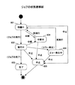
次に、図6を用いてジョブの状態遷移について説明する。図6には、状態とイベントが示されており、この図はそれらイベントによる状態遷移を示す図である。イベントには、ジョブの実行、ジョブの完了、再実行、中断、エラー発生、中止の6つある。このうち、ジョブの実行と、ジョブの完了と、エラー発生は、内部イベントである。 Next, job state transition will be described with reference to FIG. FIG. 6 shows a state and an event, and this figure shows a state transition by the event. There are six events: job execution, job completion, re-execution, interruption, error occurrence, and cancellation. Of these, job execution, job completion, and error occurrence are internal events.
基本的に、イベントが中止の場合、ジョブの状態が何であってもジョブの状態は中止605に遷移し、そのままジョブが終了するだけとなる。またイベントが再実行の場合、ジョブの状態が何であってもジョブの状態は待機中601に遷移する。 Basically, if the event is cancelled, the job state transitions to cancel 605 regardless of the job state, and the job is simply terminated. If the event is re-execution, the job state transitions to “waiting” 601 regardless of the job state.
通常、ジョブの状態は待機中601から、実行中602、そして完了603と遷移する。状態が待機中601のときは、ジョブの実行により実行中602に状態が遷移する。また、イベントが中断のときは、状態が中断中604に遷移する。
Normally, the job status changes from waiting 601 to executing 602 and then to
状態が実行中602のときは、中断、エラー発生、中止のいずれかイベントにより状態が遷移する。まず、イベントが中断のときは、状態が中断中604に遷移する。イベントがエラー発生のときは、状態がエラー発生中606に遷移する。 When the state is 602 being executed, the state is changed by any event of interruption, error occurrence, or cancellation. First, when the event is interrupted, the state transitions to suspending 604. When the event has an error, the state transitions to 606 during error occurrence.
状態が中断中604のときは、再実行または中止のイベントにより状態が遷移する。状態がエラー発生中のときは、再実行または中止のイベントにより状態が遷移する。 When the status is suspending 604, the status is changed by a re-execution or cancellation event. When the error is occurring, the status is changed by re-execution or cancellation event.
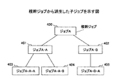
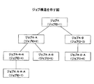
ジョブの状態遷移は以上のようになっている。次に、ジョブの派生について説明する。図7は、根幹ジョブから派生した子ジョブを示す図である。また、図7に示されるような、ジョブとジョブとの関係を示したものをジョブ構造といい、ジョブ構造を示す情報をジョブ構造情報という。このジョブ構造情報は、本実施の形態ではジョブ構造テーブルと表現され、ジョブ構造テーブルについては後に詳しく説明する。 The job state transition is as described above. Next, job derivation will be described. FIG. 7 is a diagram showing a child job derived from the basic job. In addition, as shown in FIG. 7, the relationship between jobs is shown as a job structure, and information indicating the job structure is called job structure information. This job structure information is expressed as a job structure table in the present embodiment, and the job structure table will be described in detail later.
従来技術において、根幹ジョブはスプールで処理されると消滅するので、根幹ジョブから派生した子ジョブとの親子関係が保持されることはなかった。そこで、本実施例では、どのジョブも自分から派生した全ての子ジョブの処理が終了するまで消滅しないように保持しておくようにする。 In the prior art, since the basic job disappears when it is processed by spool, the parent-child relationship with the child job derived from the basic job has not been maintained. Therefore, in this embodiment, any job is held so as not to disappear until the processing of all child jobs derived from itself is completed.
例えば、図7において、従来技術ではジョブA400は、ジョブA-A401とジョブA-B402を派生すると消滅していた。そのため図7のようなジョブ構造がMFP内では分からなかった。しかし、本実施例において、ジョブA400は子ジョブであるジョブA-A401とジョブA-B402が処理されるまで保持される。また、ジョブA-A401は子ジョブであるジョブA-A-A403とジョブA-A-B404が処理されるまで保持される。さらに、ジョブA-B402は、ジョブA-B-A405が処理されるまで保持される。このようにすることにより、図7に示すジョブ構造をMFP内で構築することが可能となる。
For example, in FIG. 7, in the prior art,
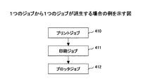
次に、ジョブの派生パターンについて説明する。図8は、1つのジョブから1つのジョブが派生するパターンを示す図である。図8には、1つのプリントジョブ410から1つの印刷ジョブ411が派生し、その印刷ジョブ411から1つのプロッタジョブ412が派生していることが示されている。
Next, a job derivation pattern will be described. FIG. 8 is a diagram illustrating a pattern in which one job is derived from one job. FIG. 8 shows that one
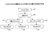
次に、図9を用いて、1つのジョブから複数のジョブが派生するパターンについて説明する。図9には、1つのプリントジョブ415から1つの印刷ジョブ416が派生し、その印刷ジョブ416から白黒プリントジョブ417、カラープリントジョブ418という2つのジョブが派生している。さらに白黒プリントジョブ417からは2つのプロッタジョブ419、420が派生している。また、カラープリントジョブ418からプロッタジョブ421が派生している。
Next, a pattern in which a plurality of jobs are derived from one job will be described with reference to FIG. In FIG. 9, one
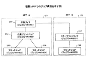
次に、複数のMFPが連携した場合のジョブ構造について説明する。図10は、2つのMFPが連携した場合のジョブ構造を示している。図10には、MFPAが実行するジョブのジョブ構造271と、MFPBが実行するジョブのジョブ構造272とが示されている。
Next, a job structure when a plurality of MFPs are linked will be described. FIG. 10 shows a job structure when two MFPs cooperate. FIG. 10 shows a
ジョブ構造271には、根幹ジョブである印刷ジョブ259と、白黒プリントジョブ254と、プロッタジョブ255、256がある。ジョブ構造272には、カラープリントジョブ257と、プロッタジョブ258がある。
The
このように、印刷ジョブ259から派生した白黒プリントジョブ254は、MFPAに、同様に派生したカラープリントジョブ257は、MFPBに割り当てることで、ジョブの分担が可能となる。
In this manner, the
なお、図10には、ジョブを特定するためのジョブIDが示されている。ジョブ構造271、272に属するジョブのジョブIDは、そのジョブIDをジョブID全体でユニークなものとされる。
FIG. 10 shows a job ID for specifying a job. The job IDs of jobs belonging to the
このジョブIDは、6ビットとされ、上位3ビットをMFPの識別コードとし、下位3ビットを、そのMFP内のジョブのなかでユニークな値としている。実際、図10において、MFPA251の識別コードは「001」とされ、MFPBの識別コードは、「002」とされている。また、各ジョブ構造に属するジョブIDの下位3ビットは、各MFP内のジョブのなかでユニークなものとなっている。 This job ID is 6 bits, with the upper 3 bits being the MFP identification code and the lower 3 bits being a unique value among the jobs in the MFP. In fact, in FIG. 10, the identification code of MFPA 251 is “001”, and the identification code of MFPB is “002”. The lower 3 bits of the job ID belonging to each job structure are unique among jobs in each MFP.
以上説明したように、ジョブの派生には、1つのジョブから1つのジョブが派生するパターンと、1つのジョブから複数のジョブが派生するパターンの2つのパターンがある。 As described above, there are two patterns of job derivation: a pattern in which one job is derived from one job and a pattern in which a plurality of jobs are derived from one job.
次に、ジョブが派生する条件について説明する。あるジョブから他のジョブが派生する条件には、処理を委譲することで他のジョブを派生する場合と、処理を分割して管理するために他のジョブを派生する場合とがある。 Next, a condition for deriving a job will be described. Conditions for deriving another job from a job include deriving another job by delegating the process, and deriving another job to manage the process in a divided manner.
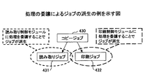
最初に、図11を用いて、処理を委譲することで他のジョブを派生する場合について説明する。処理を委譲するとは、あるソフトウェアが自分のジョブを遂行するため、他のソフトウェアに処理の一部を委譲することである。この委譲によりジョブが派生する。 First, a case where another job is derived by delegating processing will be described with reference to FIG. Delegating a process means delegating a part of the process to other software in order for a certain software to execute its own job. The job is derived by this delegation.
図11は、コピージョブ430の一部の処理を読み取り制御モジュールに委譲することで読み取りジョブ431が派生、印刷制御モジュールに委譲することで印刷ジョブ432が派生した例を示している。
FIG. 11 shows an example in which the
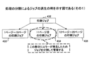
次に、図12を用いて、処理を分割して管理するために他のジョブを派生する場合について説明する。処理を分割して管理するとは、1つのソフトウェア内で、あるジョブの一部をそのジョブとは別に管理することである。この分割によりジョブが派生する。図12は処理を行った印刷ジョブ432の一部にエラーが発生したため、その部分を、正常なジョブ433、435とは別のジョブ434として分割し、個別に状態(実行中/エラーなど)を管理、操作(再実行/中止など)を行う場合の例を示している。
Next, a case where another job is derived in order to divide and manage the process will be described with reference to FIG. Dividing and managing the process means managing a part of a job separately from the job in one software. A job is derived by this division. In FIG. 12, since an error has occurred in a part of the processed
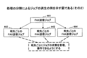
処理を分割することによるジョブの派生の他の例を、図13を用いて説明する。図13は、複数の宛先に同じ文書をFAX送信する場合に、FAX送信ジョブ441を、宛先ごとのFAX送信ジョブ442、443、444として状態を管理、操作を行う場合の例を示している。
Another example of job derivation by dividing processing will be described with reference to FIG. FIG. 13 shows an example in which, when the same document is fax-transmitted to a plurality of destinations, the
以上がジョブの派生に関する説明である。今までの説明に示されるように、本実施の形態におけるジョブとは、印刷処理、プロッタ処理、白黒プリント処理、カラープリント処理、読み取り処理、ページごとの印刷処理、宛先ごとのFAX送信処理である。しかし、これらのジョブは、例示列挙であり、他にも多くのジョブが存在する。これらのジョブを本実施の形態で示すような管理を行うことにより、ジョブの中止など、ジョブに対する操作に加え、ジョブごとに課金が可能なるなどのメリットが生じる。 This completes the explanation of job derivation. As described above, the job in the present embodiment is a printing process, a plotter process, a monochrome printing process, a color printing process, a reading process, a printing process for each page, and a FAX transmission process for each destination. . However, these jobs are exemplary listings, and many other jobs exist. By managing these jobs as shown in this embodiment, there is a merit that charging can be performed for each job in addition to operations for the job such as canceling the job.
次に、ジョブをどのようにソフトウェアが処理するかは実装方法によって異なるので、その実装方法について説明する。 Next, how the software processes the job differs depending on the mounting method, and the mounting method will be described.
ここではシングルプロセス・シングルスレッドで実装する場合、シングルプロセス・マルチスレッドで実装する場合、マルチプロセス・シングルスレッドで実装する場合、マルチプロセス・マルチスレッドで実装する場合の4例の実装方法を示す。 Here, four examples of mounting methods are shown: single-process / single-thread implementation, single-process / multi-thread implementation, multi-process / single-thread implementation, and multi-process / multi-thread implementation.
また、ここでは、ユーザのジョブへ再実行や中止などの操作をどのように実装するかも示す。なお、シングルプロセス・マルチスレッドとは、プロセスは1つだが、そのなかでは複数のスレッドがあることをいう。また、マルチプロセス・シングルスレッドとは、プロセスは複数あるが、個々のプロセスにはスレッドは1つしかないことをいう。 It also shows how to implement operations such as re-execution and cancellation on the user's job. Single process / multi-thread means that there is one process, but there are a plurality of threads. Multi-process / single thread means that there are a plurality of processes, but each process has only one thread.
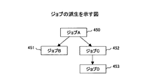
これらの例で用いられるジョブのジョブ構造を図14に示す。図14には、処理の過程でジョブA450からジョブB451とジョブC452が派生し、ジョブC452からジョブD453が派生していることが示されている。 FIG. 14 shows the job structure of the job used in these examples. FIG. 14 shows that job B451 and job C452 are derived from job A450 and job D453 is derived from job C452 in the course of processing.
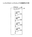
まず、図15を用いて、シングルプロセス・シングルスレッドの場合のジョブ処理の例をについて説明する。図15には、プロセスA500と、スレッドA501とが示されている。このソフトウェアのプロセスは1つ(プロセスA500)であり、スレッドもプロセスA500のメインスレッド(スレッドA501)だけである。この場合、ステップS1601でジョブAが実行される。ステップS1602でジョブBが実行される。ステップS1603でジョブCが実行される。ステップS1601でジョブDが実行される。
First, an example of job processing in the case of single process / single thread will be described with reference to FIG. FIG. 15 shows a
このように、図15のようなシングルプロセス・シングルスレッドの場合、ジョブA〜ジョブDは全てスレッドA501で処理される。 As described above, in the case of a single process / single thread as shown in FIG. 15, all of the jobs A to D are processed by the thread A501.
次に、図16を用いて、シングルプロセス・マルチスレッドの場合のジョブ処理の例を説明する。図16には、プロセスA500と、スレッドA501、スレッドB502、スレッドC503とが示されている。
Next, an example of job processing in the case of single process / multithread will be described with reference to FIG. FIG. 16 shows a
この場合、ステップS1701で、プロセスA500のメインスレッドであるスレッドA501がジョブAを実行する。このジョブAから派生したサブスレッドであるジョブBに対し、スレッドAがステップS1702で処理を依頼する。 In this case, the thread A501, which is the main thread of the process A500, executes the job A in step S1701. In step S1702, the thread A requests the job B, which is a sub thread derived from the job A, in step S1702.
そして、ステップS1703で、スレッドB502がジョブBを実行し、ステップS1704で、スレッドA501に応答を返す。さらにスレッドA501は、サブスレッドであるスレッドC503に、ステップS1705で処理を依頼する。スレッドC503は、ステップS1706でジョブCを実行し、ステップS1707で、ジョブDを実行する。そして、スレッドC503は、ステップS1708でスレッドAに応答を返す。
In step S1703, the thread B502 executes job B, and in step S1704, a response is returned to the thread A501. Furthermore, the
このように、シングルプロセス・マルチスレッドの場合、スレッドA501は、サブスレッドであるスレッドB502にジョブBを実行させ、ジョブCをサブスレッドであるスレッドC503に実行させている。さらに、ジョブCから派生したジョブDもスレッドC503に実行させている。
As described above, in the case of single process multithread, the
次に、図17を用いて、マルチプロセス・シングルスレッドの場合の例を説明する。図17には、プロセスA500と、プロセスB505と、プロセスC506と、スレッドA501、スレッドB502、スレッドC503とが示されている。
Next, an example in the case of multi-process / single thread will be described with reference to FIG. FIG. 17 illustrates a
ステップS1801で、スレッドA501は、ジョブAを実行する。ステップS1802で、スレッドA501は、プロセスB505のスレッドB502に、処理を依頼する。スレッドB502は、ステップS1803で、ジョブBを実行し、ステップS1804で、スレッドA501に応答を返す。 In step S1801, the thread A501 executes job A. In step S1802, the thread A501 requests the thread B502 of the process B505 to perform processing. In step S1803, the thread B502 executes job B, and returns a response to the thread A501 in step S1804.
スレッドA501は、ステップS1805で、プロセスC506のスレッドC503に処理を依頼する。スレッドC503は、ステップS1806で、ジョブCを実行し、さらにステップS1807で、ジョブDを実行し、ステップS1808で、スレッドAに応答を返す。 In step S1805, the thread A501 requests the thread C503 of the process C506 to perform processing. The thread C503 executes job C in step S1806, further executes job D in step S1807, and returns a response to the thread A in step S1808.
このように、マルチプロセス・シングルスレッドの場合、プロセスA500のメインスレッドであるスレッドA501でジョブAを実行する。そして、スレッドA501は、ジョブAから派生したジョブBをプロセスB505のメインスレッドであるスレッドB502に、ジョブCをプロセスC506のメインスレッドであるスレッドC503に実行させている。さらに、スレッドA501は、ジョブCから派生したジョブDもスレッドC503に実行させている。
Thus, in the case of multi-process / single thread, the job A is executed by the
次に、図18を用いて、マルチプロセス・マルチスレッドの場合の例を説明する。図18には、プロセスA500と、プロセスB505と、スレッドA501、スレッドB502、スレッドC503、スレッドD507とが示されている。
Next, an example of multi-process / multi-thread will be described with reference to FIG. FIG. 18 illustrates a
ステップS1901で、プロセスA500のスレッドA501は、ジョブAを実行する。ステップS1902でスレッドA501は、同じプロセスA500内のスレッドB502に処理を依頼する。スレッドB502は、ステップS1903で、ジョブBを実行し、ステップS1904で、スレッドA501に応答を返す。 In step S1901, the thread A501 of the process A500 executes the job A. In step S1902, the thread A501 requests the thread B502 in the same process A500 to perform processing. In step S1903, the thread B502 executes job B, and returns a response to the thread A501 in step S1904.
スレッドA501は、ステップS1905で、プロセスB505のスレッドC503に処理を依頼する。スレッドC503は、ステップS1906で、ジョブCを実行する。ステップS1907でスレッドC503は、同じプロセスB505内のスレッドD507に処理を依頼する。スレッドD507は、ステップS1908で、ジョブDを実行し、ステップS1909で、スレッドC503に応答を返す。スレッドC503は、ステップS1910で、スレッドA501に応答を返す。 In step S1905, the thread A501 requests the thread C503 of the process B505 to perform processing. In step S1906, the thread C503 executes job C. In step S1907, the thread C503 requests the thread D507 in the same process B505 to perform processing. The thread D507 executes the job D in step S1908, and returns a response to the thread C503 in step S1909. In step S1910, the thread C503 returns a response to the thread A501.
このように、マルチプロセス・マルチスレッドの場合、プロセスA500のメインスレッドであるスレッドA501でジョブAが処理される。また、スレッドA501は、ジョブAから派生したジョブBをプロセスA500のサブスレッドであるスレッドB502に実行させる。また、スレッドA501は、ジョブAから派生したジョブCをプロセスB505のメインスレッドであるスレッドC503に実行させ、ジョブCから派生したジョブDをプロセスB505のサブスレッドであるスレッドD507に実行させている。
As described above, in the case of multi-process / multi-thread, the job A is processed by the
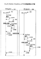
以上が4例の実装方法である。これらの実装方法に加え、さらにマルチプロセス・マルチスレッドという実装方法において、ユーザからの要求によりジョブの処理を操作する例を、図19を用いて説明する。図19には、プロセスA500と、プロセスB505と、プロセスC506と、スレッドA501と、スレッドB502と、スレッドC503と、スレッドE508とが示されている。
The above is the four example mounting methods. In addition to these mounting methods, an example of operating a job process according to a request from a user in a mounting method called multi-process / multi-thread will be described with reference to FIG. FIG. 19 shows a
このうち、プロセスCがユーザからの要求が行われるプロセスとなっている。ステップS2001で、プロセスA500のスレッドA501は、ジョブAを実行する。ステップS2002でスレッドA501は、同じプロセスA500内のスレッドB502に処理を依頼する。スレッドB502は、ステップS2003で、ジョブBを実行し、ステップS2004で、スレッドA501に応答を返す。 Among these, the process C is a process in which a request from the user is performed. In step S2001, the thread A501 of the process A500 executes the job A. In step S2002, the thread A501 requests the thread B502 in the same process A500 to perform processing. The thread B502 executes the job B in step S2003, and returns a response to the thread A501 in step S2004.
スレッドA501は、ステップS2005で、プロセスB505のスレッドC503に処理を依頼する。スレッドC503は、ステップS2006で、ジョブCを実行する。 In step S2005, the thread A501 requests the thread C503 of the process B505 to perform processing. In step S2006, the thread C503 executes job C.
このとき、ステップS2007でプロセスC506のスレッドE508は、スレッドC503に処理の中止を依頼する。スレッドC503は、ステップS2008で、ジョブCの中止処理を実行し、ステップS2009で、スレッドA501に応答を返す。 At this time, in step S2007, the thread E508 of the process C506 requests the thread C503 to cancel the process. In step S2008, the thread C503 executes job C cancellation processing, and in step S2009, a response is returned to the thread A501.
このように、ユーザからの操作の場合、操作の受付用のプロセス(プロセスC506)が存在し、ユーザからの中止要求を受け付け、該当するジョブに中止依頼を出すようになっている。 As described above, in the case of an operation from the user, there is a process for accepting the operation (process C506), and a cancel request from the user is received and a cancel request is issued to the corresponding job.
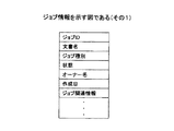
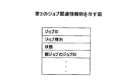
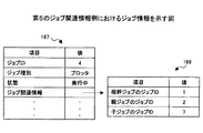
次に、各ジョブに関する情報であるジョブ情報について、図20を用いて説明する。ジョブ情報は、図20に示されるように、識別情報に対応するジョブIDと、文書名と、ジョブ種別と、状態と、オーナー名と、作成日と、ジョブ関連情報とを有する。 Next, job information that is information relating to each job will be described with reference to FIG. As shown in FIG. 20, the job information includes a job ID corresponding to the identification information, a document name, a job type, a state, an owner name, a creation date, and job related information.
このうち、ジョブ関連情報が、ジョブのジョブ構造をMFP内で構築することを可能とするものであり、このジョブ関連情報については後に詳しく説明することとする。ジョブ構造を構築することが可能であれば、ジョブの親子関係が分かる。 Of these, the job related information makes it possible to build the job structure of the job in the MFP, and this job related information will be described in detail later. If the job structure can be constructed, the parent-child relationship of the job can be understood.
上記ジョブ情報のうち、ジョブIDは、「1」や「2」など、各ジョブを識別するもので、各ジョブに一意的に割り当てられるものである。以下の説明では、ジョブIDがnのジョブを単にジョブnと表現することがある。 In the job information, the job ID identifies each job such as “1” or “2”, and is uniquely assigned to each job. In the following description, a job having a job ID n may be simply expressed as job n.
文書名は、印刷する文書の名前を示すもので、例えば文字列で表現される。ジョブ種別は、「印刷」、「FAX送信」など、どのような処理のジョブかを示すものである。「状態」は、「実行中」や「エラー」など、ジョブの状態を示すものである。「オーナー名」は、「鈴木」、「佐藤」など、ジョブの実行を依頼したユーザ名を示すものである。「作成日」は、「2004.02.17.12:15」など、ジョブが作成された日時を示すものである。 The document name indicates the name of the document to be printed, and is represented by a character string, for example. The job type indicates what kind of processing the job is, such as “print” or “FAX transmission”. The “status” indicates the status of the job such as “running” or “error”. “Owner name” indicates the name of the user who requested execution of the job, such as “Suzuki” or “Sato”. “Created date” indicates the date and time when the job was created, such as “2004.02.17.12:15”.
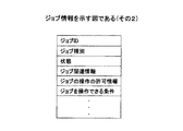
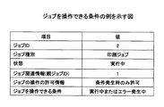
ジョブ情報の他の例を、図21を用いて説明する。図21に示されるジョブ情報と、図20に示されるジョブ情報とが異なる大きな点は、「ジョブの操作の許可情報」と「ジョブを操作できる条件」なる2つの項目である。 Another example of job information will be described with reference to FIG. The major difference between the job information shown in FIG. 21 and the job information shown in FIG. 20 is two items, “job operation permission information” and “job operation condition”.
これらの項目は、ジョブの操作、ジョブの状態閲覧を可能とするための項目である。個々のジョブは実行中やエラー発生中などの状態を持ち、そのジョブに対してユーザが再実行や中止などの操作を行うことができる。 These items are items for enabling job operation and job status browsing. Each job has a status such as executing or error occurrence, and the user can perform operations such as re-execution and cancellation for the job.
しかし、ジョブによってはユーザに操作させなかったり、ある条件を満たす時に限り操作を許したりするものもある。そのような形にジョブを実装する場合、ジョブ情報に図21に示すような「ジョブの操作の許可情報」や「ジョブを操作できる条件」という属性を付加する必要がある。 However, some jobs may not be operated by the user, or may be permitted only when certain conditions are met. When a job is mounted in such a form, it is necessary to add attributes such as “job operation permission information” and “job operation condition” as shown in FIG.
このうち、「ジョブの操作の許可情報」について説明する。この「ジョブの操作の許可情報」が取り得る値には「許可」、「不許可」、「条件発生時のみ許可」がある。 Of these, “job operation permission information” will be described. Possible values of the “job operation permission information” include “permitted”, “not permitted”, and “permitted only when a condition occurs”.
「許可」とは、どのような場合でもそのジョブの状態に見合った操作(再実行/中止/中断など)が行えることを示す。「不許可」とは、どのような場合でもそのジョブに対しては操作が行えないことを示す。「条件発生時のみ許可」とは、図21に示される「ジョブを操作できる条件」が成就した時に、その条件に見合った操作を行えることを示す。具体的に、操作として、エラー発生の場合の再実行または中止が挙げられる。 “Allowed” indicates that in any case, an operation (re-execution / cancellation / interruption, etc.) corresponding to the job status can be performed. “Non-permitted” indicates that an operation cannot be performed on the job in any case. “Allow only when condition occurs” indicates that when the “condition for operating a job” shown in FIG. 21 is fulfilled, an operation corresponding to the condition can be performed. Specifically, the operation includes re-execution or cancellation when an error occurs.
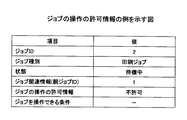
これらの値のうち、「不許可」の場合のジョブ情報を示すのが、図22に示されるジョブ情報である。このジョブ情報の「ジョブの操作の許可情報」は「不許可」となっている。また、「条件発生時のみ許可」の場合のジョブ情報を示すのが、図23に示されるジョブ情報である。このジョブ情報の「ジョブの操作の許可情報」は「条件発生時のみ許可」となっており、「ジョブを操作できる条件」が「実行中&エラー発生中」であることが示されている。 Among these values, job information shown in FIG. 22 indicates job information in the case of “not permitted”. The “job operation permission information” of the job information is “not permitted”. In addition, job information shown in FIG. 23 indicates job information in the case of “permit only when a condition occurs”. In this job information, “job operation permission information” is “permitted only when a condition occurs”, and “condition that the job can be operated” is “execution & error is occurring”.
なお、「ジョブを操作できる条件」は、「エラー発生中」、「実行中またはエラー発生中」、「待機中またはエラー発生中」、「実行中または待機中&エラー発生中」の値もとり得る。「エラー発生中」は、ジョブがエラー発生中という条件である。「実行中またはエラー発生中」は、ジョブが実行中もしくはジョブがエラー発生中という条件である。「待機中またはエラー発生中」は、ジョブが待機中もしくはジョブがエラー発生中という条件である。「実行中または待機中またはエラー発生中」は、ジョブが実行中、ジョブが待機中、ジョブがエラー発生中のうちのいずれか条件である。 Note that the “condition for operating the job” can also take the values “error is occurring”, “running or error is occurring”, “waiting or error is occurring”, “running or waiting & error is occurring” . “Error is occurring” is a condition that the job is in error. “During execution or error occurrence” is a condition that the job is being executed or the job is in error. “Waiting or generating an error” is a condition that the job is waiting or the job is generating an error. “Executing or waiting or error is occurring” is one of the following conditions: the job is being executed, the job is waiting, or the job is in error.
次に、ジョブ関連情報に基づき作成されるジョブ構造テーブルについて、図24を用いて説明する。ジョブ構造テーブル100は、親ジョブと子ジョブのIDからなるものである。「子ジョブ」は、ジョブIDを示し、「親ジョブ」は、子ジョブで示されたジョブIDを有するジョブの親ジョブのジョブIDを示している。従って、親ジョブが記入されていないジョブは、親ジョブが存在しないジョブなので、根幹ジョブということになる。 Next, a job structure table created based on job related information will be described with reference to FIG. The job structure table 100 includes parent job and child job IDs. “Child Job” indicates the job ID, and “Parent Job” indicates the job ID of the parent job of the job having the job ID indicated by the child job. Therefore, a job in which no parent job is entered is a basic job because there is no parent job.
また、ジョブ構造101、102は、ジョブ構造テーブル100をジョブ構造として表現したものである。
図24の場合、ジョブ1と、ジョブ8は根幹ジョブであることが分かる。また、ジョブ構造テーブル100には、ジョブ2、3のジョブの親ジョブのIDが1と示されてあるので、ジョブ2、3は、ジョブ1から派生したジョブであることが分かる。同様に、他のジョブに関しても、ジョブ構造テーブル100に示される各ジョブIDにより、図24に示されるジョブ構造を生成できる。
In the case of FIG. 24, it can be seen that
このように、ジョブの親ジョブのジョブIDを各ジョブごとに保持しておくとことで、ジョブ構造テーブルを作成することができる。また、このジョブ構造テーブルにより、パソコンの画面、あるいはMFPに設けられているオペレーションパネルにジョブ構造を表示することができる。 As described above, the job structure table can be created by storing the job ID of the parent job of each job for each job. Further, the job structure table can display the job structure on the screen of the personal computer or the operation panel provided in the MFP.
なお、ジョブ構造テーブルは、図25に示されるように、XMLで表現することもできる。図25に示されるXML文は、図24で示した根幹ジョブで、ジョブ8から派生したジョブのジョブ構造102を生成するためものである。
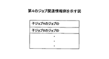
The job structure table can also be expressed in XML as shown in FIG. The XML statement shown in FIG. 25 is for generating the
この図25より、ジョブ8は、ジョブ9、10、11のジョブを、子ジョブあるいは孫ジョブとしていることが分かる。同様に、ジョブ9は、ジョブ8を親ジョブとし、ジョブ10、11を子ジョブとしていることが分かる。さらにジョブ10、11は、ともにジョブ9を親ジョブとしていることが分かる。
From FIG. 25, it can be seen that the
このようにジョブ構造テーブルは、ジョブIDを入れ子とするXML文で表現することができる。 As described above, the job structure table can be expressed by an XML sentence in which job IDs are nested.
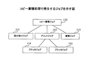
以上が処理の概要である。次に、各処理の詳細な説明をする。まず、図26を用いてMFPに発生するジョブを、コピーを例にして説明する。図26には、コピー蓄積ジョブ110と、読み取りジョブ111と、プリントジョブ112と、蓄積ジョブ113と、プロッタジョブ114、115が示されている。このジョブ構造における根幹ジョブは、コピー蓄積ジョブ110である。
The above is the outline of the processing. Next, each process will be described in detail. First, a job generated in the MFP will be described with reference to FIG. 26 shows a
コピー蓄積の要求に対して、コピー蓄積ジョブ110が発生し、それを実現するために読み取りジョブ111、プリントジョブ112、蓄積ジョブ113が派生する。プリントジョブ112からは、さらにプロッタジョブ114、115が派生する。
In response to a copy accumulation request, a
次に、図27を用いて、MFPのソフトウェアブロックについて説明する。この図27で説明される「アプリ」、「モジュール」、「ハンドラ」をまとめて、プログラムということにする。 Next, a software block of the MFP will be described with reference to FIG. The “application”, “module”, and “handler” described in FIG. 27 are collectively referred to as a program.
図27に示されるソフトウェアブロックは、アプリケーション層5と、サービス層7と、ハンドラ層9の3つの層に分けられる。アプリケーション層5は、コピーアプリ21と、プリンタアプリ20と、FAXアプリ22などのプログラムを含む。サービス層7は、印刷制御モジュール23と、FAX制御モジュール24と、読み取り制御モジュール25と、ジョブ管理モジュール26のプログラムを含む。ハンドラ層9は、プロッタハンドラ27と、FAXユニットハンドラ28と、スキャナハンドラ29と、メモリ管理モジュール30のプログラムを含む。
The software block shown in FIG. 27 is divided into three layers: an
アプリケーション層5のコピーアプリ21、プリンタアプリ20、FAXアプリ22は、それぞれ、コピー用、プリンタ用、FAX用のアプリケーションである。
The
次に、サービス層7のモジュールについて説明する。印刷制御モジュール23は、印刷処理を制御するモジュールである。FAX制御モジュール24は、FAX処理を制御するモジュールである。読み取り制御モジュール25は、読み取り処理を制御するモジュールである。ジョブ構造情報作成手段に対応するジョブ管理モジュール26は、要求によりジョブ構造テーブル(ジョブ構造情報)を作成して要求元に渡すモジュールである。
Next, the module of the
次に、ハンドラ層9のプログラムについて説明する。ハンドラ層9のプログラムは、ハードウェアであるプロッタやスキャナなどのハンドラなどである。
Next, the program of the
プロッタハンドラ27は、プロッタのハンドラである。FAXユニットハンドラ28は、FAXユニットのハンドラである。スキャナハンドラ29は、スキャナのハンドラである。記憶管理手段に対応するメモリ管理モジュール30は、メモリやハードディスクの管理を行うハンドラである。以上説明した各プログラムで、自らジョブを生成するプログラムは、ジョブ関連情報生成手段に対応する。
The
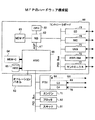
次に、MFPのハードウェア構成図を、図28を用いて説明する。MFPは、コントローラボード60と、オペレーションパネル53と、FCU68と、エンジン71と、スキャナ51と、プロッタ52とを含む。また、FCU68は、G3規格対応ユニット69と、G4規格対応ユニット70とを有する。
Next, a hardware configuration diagram of the MFP will be described with reference to FIG. The MFP includes a
また、コントローラボード60は、CPU61と、ASIC66と、HDD65と、ローカルメモリ(MEM−C)64と、システムメモリ(MEM−P)63と、ノースブリッジ(以下、NBと記す)62と、サウスブリッジ(以下、SBと記す)73と、NIC74(Network Interface Card)と、USBデバイス75と、IEEE1394デバイス76と、セントロニクスデバイス77とを含む。
The
オペレーションパネル53は、コントローラボード60のASIC66に接続されている。また、SB73と、NIC74と、USBデバイス75と、IEEE1394デバイス76と、セントロニクスデバイス77と、NB62にPCIバスで接続されている。
The
また、FCU68と、エンジン71と、スキャナ51、プロッタ52は、コントローラボード60のASIC66にPCIバスで接続されている。
The
なお、コントローラボード60は、ASIC66にローカルメモリ64、HDD65などが接続されると共に、CPU61とASIC66とがCPUチップセットのNB62を介して接続されている。このように、NB62を介してCPU61とASIC66とを接続すれば、CPU61のインタフェースが公開されていない場合に対応できる。
In the
なお、ASIC66とNB62とはPCIバスを介して接続されているのでなく、AGP(Accelerated Graphics Port)67を介して接続されている。このように、図27のアプリケーション層5などを形成する一つ以上のプロセスを実行制御するため、ASIC66とNB62とを低速のPCIバスでなくAGP67を介して接続し、パフォーマンスの低下を防いでいる。
The
CPU61は、MFPの全体制御を行うものである。CPU61は、アプリケーション層5、サービス層7、ハンドラ層9に含まれるプログラムをOS上にそれぞれプロセスとして起動して実行させる。
The
NB62は、CPU61、システムメモリ63、SB73およびASIC66を接続するためのブリッジである。システムメモリ63は、MFPの描画用メモリなどとして用いるメモリである。SB73は、NB62とPCIバス、周辺デバイスとを接続するためのブリッジである。また、ローカルメモリ64はコピー用画像バッファ、符号バッファとして用いるメモリである。
The
ASIC66は、画像処理用のハードウェア要素を有する画像処理用途向けのICである。HDD65は、画像データの蓄積、文書データの蓄積、プログラムの蓄積、フォントデータの蓄積、フォームの蓄積などを行うためのストレージである。また、オペレーションパネル53は、ユーザからの入力操作を受け付けると共に、ユーザに向けた表示を行う操作部である。
The
次に、上述した各ソフトウェアの関係と、各ソフトウェア間でやり取りされる情報について、図29と図30を用いて説明する。図29は、ジョブ情報がHDD65に記憶される場合を示す図であり、図30は、ジョブ情報がメモリ上に記憶される場合を示す図である。
Next, the relationship between the above-described software and information exchanged between the software will be described with reference to FIGS. 29 and 30. FIG. FIG. 29 is a diagram illustrating a case where job information is stored in the
まず、図29の説明をする。図29には、各プログラム130と、メモリ管理モジュール30と、HDD65と、ジョブ情報132と、ジョブ管理モジュール26と、表示アプリ32と、専用キュー131とが示されている。
First, FIG. 29 will be described. FIG. 29 shows each
各プログラム130は、アプリ層、サービス層、ハンドラ層の各プログラムである。具体的には、ジョブ管理モジュールとメモリ管理モジュール以外のプログラムであり、ジョブを発生・処理するプログラムである。表示アプリ32は、パソコンで表示するPCアプリや、上述したオペレーションパネル用のアプリである。ジョブ情報132は、図20で説明したジョブ情報であり、図29の場合、HDD65に記憶されている。専用キュー131は、各プログラム用のメモリ空間に記憶される各プログラムがジョブを管理する専用のキューである。
Each
なお、各プログラムのメモリ空間とは、そのプログラムにそれぞれ割り当てられたメモリ領域を指す。ここに各モジュールは専用のキューを持っており、処理するジョブの順番を管理している。 Note that the memory space of each program refers to a memory area allocated to the program. Each module has a dedicated queue and manages the order of jobs to be processed.
各プログラム130からメモリ管理モジュール30へはジョブ情報が提供される。メモリ管理モジュール30は、ジョブ情報をHDD65に記憶する。また、メモリ管理モジュール30は、ジョブ管理モジュール26にジョブ情報を提供する。ジョブ管理モジュール26は、表示アプリ32にジョブ構造テーブルとジョブ情報を提供する。各プログラム130は、ジョブ管理モジュール26にキューの情報を提供する。また、各プログラム130は、専用キュー131にジョブIDを記憶させる。
Job information is provided from each
次に、図30の説明をする。なお、図29で説明した参照符号と同じものは、説明を省略する。図30と図29で異なるのは、キュー133とジョブ情報132である。キュー133とジョブ情報132は、図30に示されるように、各プログラム用のメモリ空間に記憶される。従って、キュー133とジョブ情報132は、各プログラム専用のものとなる。
Next, FIG. 30 will be described. Note that the description of the same reference numerals as those described in FIG. 29 is omitted. The difference between FIG. 30 and FIG. 29 is the
各プログラム130は、キュー133とジョブ情報132にそれぞれジョブIDとジョブ情報を記憶させる。また、各プログラム130は、ジョブ管理モジュール26にキューの情報とジョブ情報を提供する。ジョブ管理モジュール26は、表示アプリ32にジョブ構造テーブルとジョブ情報を提供する。
Each
この図30の場合、ジョブ情報はHDDではなく各プログラムが管理するメモリ空間で保存されている。よって、ジョブ管理モジュール62はジョブを持っている各プログラムからジョブ情報を取得し、ジョブ構造テーブルを作成する。
In the case of FIG. 30, job information is stored not in the HDD but in a memory space managed by each program. Therefore, the
次に、ジョブ関連情報について説明する。このジョブ関連情報は上述したように、ジョブ構造テーブルの作成に必要なものである。このジョブ関連情報は、ジョブ構造テーブルを作成できればよいので、いくつかの種類が考えられる。以下、7種類のジョブ関連情報の例とそのときの処理を示すシーケンス図について説明する。シーケンス図で説明する処理は、印刷要求を行ったときのジョブ登録処理と、ジョブの参照を行ったときの処理である。 Next, job related information will be described. As described above, this job related information is necessary for creating the job structure table. There are several types of job related information as long as a job structure table can be created. Hereinafter, an example of seven types of job related information and a sequence diagram showing processing at that time will be described. The processes described in the sequence diagram are a job registration process when a print request is made and a process when a job is referred to.
なお、それぞれで示されるジョブ情報は図20または図21で説明した構造を例としている。また、以下の説明で用いられるジョブ構造は、図31に示されるジョブ構造とする。図31に示されるジョブ構造は、ジョブAから派生したジョブで構成されるジョブのジョブ構造である。また、各シーケンス図において、「ジョブの生成」なる記載があるが、このジョブを生成する段階が、ジョブ関連情報生成段階に対応する。さらに、「ジョブ一覧の作成」を行う段階は、ジョブ構造情報作成段階に対応する。「ジョブ情報の保存」を行う段階は、記憶管理段階に対応する。 Note that the job information shown in each example has the structure described in FIG. 20 or 21 as an example. Further, the job structure used in the following description is the job structure shown in FIG. The job structure shown in FIG. 31 is a job structure of a job composed of jobs derived from job A. In each sequence diagram, there is a description of “job generation”, but the stage of generating this job corresponds to the stage of generating job related information. Furthermore, the stage of “creating a job list” corresponds to the stage of creating job structure information. The stage of “saving job information” corresponds to the storage management stage.
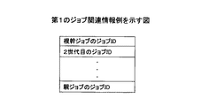
第1のジョブ関連情報例について、図32を用いて説明する。図32に示されるジョブ関連情報は、子ジョブの親ジョブのジョブIDから根幹ジョブのジョブIDまで、というように、子ジョブが全ての先祖のジョブのジョブIDを持っているものである。 A first job related information example will be described with reference to FIG. The job-related information shown in FIG. 32 is that the child job has the job IDs of all ancestor jobs, such as from the job ID of the parent job of the child job to the job ID of the basic job.
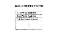
具体的に、図33に示されるジョブ情報を用いて説明する。この図33に示されるジョブ情報は、図31のジョブ7のジョブ情報である。
This will be specifically described using the job information shown in FIG. The job information shown in FIG. 33 is the job information of
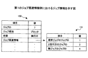
図33には、ジョブ情報150と、ジョブ関連情報151とが示されている。ジョブ情報150は、図20で説明したものである。ジョブ関連情報151は、項目に「根幹ジョブのジョブID」と「2世代目のジョブID」と、「親ジョブのジョブID」があり、それぞれ値が「1」、「2」、「4」となっている。
FIG. 33
実際に、ジョブ7の親ジョブはジョブ4であり、2世代目のジョブはジョブ2であり、根幹ジョブはジョブ1である。
Actually, the parent job of
このように、子ジョブが全ての先祖のジョブのジョブIDを持っており、ジョブ管理モジュールが末端ジョブを識別する仕組みが構築されると、ジョブ管理モジュールは末端ジョブの情報を取得するだけで、ジョブ構造テーブルを作成できる。また、アプリ層、サービス層、ハンドラ層の各プログラムは、ジョブ生成時に、親ジョブのジョブ構造テーブルに、親のジョブIDを追記するだけで、ジョブ関連情報を作成できる。なお、ジョブ管理モジュールが末端ジョブを識別する仕組みとして、ジョブ情報に末端ジョブかを判別するフラグを設けるなどの仕組みが挙げられる。 In this way, when the child job has the job IDs of all ancestor jobs and the job management module identifies a terminal job, the job management module simply acquires the information of the terminal job. A job structure table can be created. The application layer, service layer, and handler layer programs can create job-related information simply by adding the parent job ID to the job structure table of the parent job at the time of job generation. As a mechanism for identifying the end job by the job management module, there is a mechanism such as providing a flag for determining whether the job is the end job in the job information.
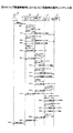
以上説明した第1のジョブ関連情報例の場合の処理を、シーケンス図を用いて説明する。図34は、ジョブ登録時の動作シーケンスを示すもので、ユーザ160と、プリンタアプリ20と、印刷制御モジュール23と、プロッタハンドラ27と、メモリ管理モジュール30との間で行われる処理を示している。このことは、以降のジョブ登録時の動作シーケンス図でもほぼ同じである。
Processing in the case of the first job related information example described above will be described with reference to a sequence diagram. FIG. 34 shows an operation sequence at the time of job registration, and shows processing performed among the
ステップS101で、プリンタアプリ20は、ユーザ160から印刷要求を通知される。プリンタアプリ20は、ステップS102で、ジョブの生成を行い、ステップS103で、ジョブIDをキューに追加する。ステップS104で、プリンタアプリ20は、メモリ管理モジュールにジョブ情報を通知することで、ジョブ情報を保存する。
In step S <b> 101, the
ステップS105で、プリンタアプリ20は、キューからジョブIDを取得する。ステップS107で、メモリ管理モジュール30は、プリンタアプリ20にジョブ情報を通知する。ステップS108は、プリンタアプリ20の処理の実行である。
In step S105, the
ステップS109で、プリンタアプリ20は、印刷制御モジュール23に印刷処理要求を通知する。このとき、親ジョブのジョブ関連情報と、親ジョブのジョブIDも通知される。印刷モジュール23は、ステップS110でジョブの生成を行い、ステップS111でジョブIDをキューに追加する。そして、ステップS112で印刷制御モジュール23は、ジョブ情報を保存する。次のステップS113で、印刷制御モジュール23は、ジョブIDをキューから取得する。
In step S <b> 109, the
印刷制御モジュール23は、ステップS114で、メモリ管理モジュール30にジョブ情報の取得を要求する。メモリ管理モジュール30は、ステップS115で、印刷制御モジュール23にジョブ情報を通知する。
In step S114, the
ステップS116は、印刷制御モジュール23の処理の実行である。ステップS117で印刷制御モジュール23は、プロッタハンドラ27にプロット要求を通知する。このとき、親ジョブのジョブ関連情報と親ジョブIDも通知される。
Step S <b> 116 is execution of processing of the
ステップS118で、プロッタハンドラ27は、ジョブの生成を行う。ステップS119で、プロッタハンドラ27は、ジョブIDをキューに追加し、ステップS120で、ジョブ情報を保存する。ステップS121で、プロッタハンドラ27は、ジョブIDをキューから取得する。ステップS122で、プロッタハンドラ27は、メモリ管理モジュール30にジョブ情報の取得を要求する。ステップS123で、メモリ管理モジュール30は、プロッタハンドラ27にジョブ情報を通知する。
In step S118, the
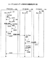
プロッタハンドラ27は、ステップS124で、プロットを実行する。プロッタハンドラ27は、印刷制御モジュール23に、ステップS125で、プロット終了を通知する。印刷制御モジュール23は、ステップS126で、プリンタアプリ20に印刷終了を通知する。プリンタアプリ20は、ステップS127で、ユーザ160に印刷終了を通知(表示)する。
The
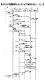
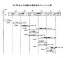
次に、図35を用いて、ジョブ参照時の動作シーケンスを説明する。図35は、ユーザ160と、オペパネアプリ161と、ジョブ管理モジュール26と、メモリ管理モジュール30と、プリンタアプリ20との間で行われる処理を示している。このことは、以降のジョブ参照時の動作シーケンス図でもほぼ同じである。
Next, an operation sequence at the time of job reference will be described with reference to FIG. FIG. 35 shows processing performed among the
ステップS201で、オペパネアプリ161は、ユーザ160からジョブ参照要求を通知される。ステップS202で、オペパネアプリ161は、ジョブ管理モジュール26にジョブ一覧要求を通知する。ジョブ管理モジュール26は、ステップS203で、メモリ管理モジュール30に末端ジョブの検索を通知する。ステップS204で、メモリ管理モジュール30は、ジョブ管理モジュール26に末端ジョブの検索結果を通知する。ステップS205で、ジョブ管理モジュール26は、メモリ管理モジュール30にジョブ情報の取得を要求する。ステップS206で、メモリ管理モジュール30は、ジョブ管理モジュール26にジョブ情報を通知する。ジョブ管理モジュール26は、ステップS207で、ジョブ一覧の作成を行う。
In step S <b> 201, the
ステップS208で、ジョブ管理モジュール26は、オペパネアプリ161にジョブ一覧を通知する。オペパネアプリ161は、ステップS209で、ユーザ160に、ジョブ一覧を通知(表示)する。ステップS210で、オペパネアプリ161は、ユーザ160からジョブ情報を要求される。ステップS211で、オペパネアプリ161は、ジョブ管理モジュール26にジョブ情報の取得を要求する。ジョブ管理モジュール26は、ステップS212で、メモリ管理モジュール30にジョブ情報の取得を要求する。メモリ管理モジュール30は、ステップS213で、ジョブ管理モジュール26にジョブ情報を通知する。
In step S208, the
ステップS214で、ジョブ管理モジュール26は、プリンタアプリ20に、キューの順番取得を要求する。プリンタアプリ20は、ステップS215で、ジョブ管理モジュール26にキューの順番を通知する。ジョブ管理モジュール26は、ステップS216で、オペパネアプリ161にジョブ情報を通知する。ステップS217で、オペパネアプリ161は、ユーザ160にジョブ情報を通知(表示)する。
In step S214, the
次に、第2のジョブ関連情報例について、図36を用いて説明する。第2のジョブ関連情報例は、図36に示されるように、ジョブ情報内のジョブ関連情報に、親ジョブのジョブIDのみを持っているものである。 Next, a second job related information example will be described with reference to FIG. In the second job related information example, as shown in FIG. 36, the job related information in the job information has only the job ID of the parent job.
具体的に、図37に示されるジョブ情報を用いて説明する。この図37に示されるジョブ情報は、図31のジョブ7のジョブ情報である。ジョブ関連情報は、項目に「親ジョブのジョブID」のみであり、値が「4」となっている。
Specifically, description will be made using the job information shown in FIG. The job information shown in FIG. 37 is the job information of
このように、ジョブ関連情報が親ジョブのジョブIDのみであれば、ジョブ情報の情報量を抑えることが可能となる。この場合、ジョブ管理モジュールが全ジョブにアクセスする仕組みが必要となる。 Thus, if the job related information is only the job ID of the parent job, the amount of job information can be suppressed. In this case, a mechanism is required for the job management module to access all jobs.
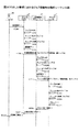
以上説明した第2のジョブ関連情報例の場合のジョブ登録時の動作を、図38のシーケンス図を用いて説明する。なお、このシーケンス図は、図34で示したシーケンス図でのステップのうち、2つのステップ以外は同じであるので、異なるステップ以外の説明は省略する。 The operation at the time of job registration in the case of the second job related information example described above will be described with reference to the sequence diagram of FIG. Note that this sequence diagram is the same as the sequence diagram shown in FIG. 34 except for two steps, and therefore the description other than the different steps will be omitted.
異なるステップは、図34におけるステップS109とステップS117であり、図38では、それぞれステップS309とステップS317に対応する。 The different steps are step S109 and step S117 in FIG. 34, and correspond to step S309 and step S317 in FIG. 38, respectively.
ステップS109では、親ジョブのジョブ関連情報が通知されるが、ステップS309では、親ジョブのジョブIDのみが通知される。また、ステップS117も同様に、親ジョブのジョブ関連情報と親ジョブのジョブIDの2つが通知されるが、ステップS317では、親ジョブのジョブIDのみが通知される。 In step S109, the job related information of the parent job is notified, but in step S309, only the job ID of the parent job is notified. Similarly, in step S117, the job related information of the parent job and the job ID of the parent job are notified, but only the job ID of the parent job is notified in step S317.
いずれのステップの処理も、ジョブ関連情報が親ジョブのジョブIDとなったことによるものである。 The processing in any step is due to the fact that the job related information becomes the job ID of the parent job.
次に、図39を用いて、ジョブ参照時の動作シーケンスを説明する。なお、このシーケンス図は、図35で示したシーケンス図のステップS201、202は、ステップS401、402に対応し、ステップS205からステップS217は、ステップS404からステップS415に対応する。 Next, an operation sequence at the time of job reference will be described with reference to FIG. In this sequence diagram, steps S201 and 202 in the sequence diagram shown in FIG. 35 correspond to steps S401 and 402, and steps S205 to S217 correspond to steps S404 to S415.
従って、図39に示される処理は、図35の処理から、末端ジョブの検索処理であるステップS203、204の処理を除いたものである。これは、ジョブ管理モジュールが全ジョブにアクセスするため、特定のジョブの検索の必要がないためである。 Therefore, the processing shown in FIG. 39 is obtained by removing the processing of steps S203 and S204, which is the end job search processing, from the processing of FIG. This is because there is no need to search for a specific job because the job management module accesses all jobs.
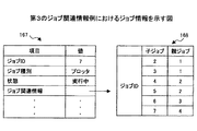
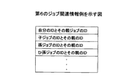
次に、第3のジョブ関連情報例について、図40を用いて説明する。図40に示されるジョブ関連情報は、ジョブが全ての子孫ジョブのジョブIDを持っているものである。 Next, a third job related information example will be described with reference to FIG. The job related information shown in FIG. 40 indicates that the job has the job IDs of all the descendant jobs.
具体的に、図41に示されるジョブ情報を用いて説明する。図41には、ジョブ情報167と、ジョブ関連情報168とが示されている。ジョブ情報167に示されるように、このジョブ情報は、図31に示されているジョブ7のジョブ情報である。
Specifically, description will be made using the job information shown in FIG. FIG. 41
ジョブ関連情報168は、値に「子ジョブ」と「親ジョブ」がある。子ジョブで示されるジョブIDの親ジョブのジョブIDが親ジョブの欄に記載される。
The job
実際に、ジョブ2、3の親ジョブはジョブ1であり、ジョブ4、5の親ジョブは、ジョブ2であり、ジョブ6の親ジョブはジョブ3であり、ジョブ7の親ジョブはジョブ4である。
Actually, the parent job of
このように、ジョブ関連情報が子孫ジョブのジョブIDあれば、ジョブ管理モジュールは、根幹ジョブのジョブ情報を取得するだけでジョブ構造テーブルの作成が可能となる。この場合、ジョブを生成したモジュールが、先祖のジョブを生成した全モジュールにジョブIDを通知する仕組みが必要である。さらに、ジョブ管理モジュールが保存されているジョブから根幹ジョブを探す仕組みが必要である。 As described above, if the job-related information is the job ID of the descendant job, the job management module can create the job structure table only by acquiring the job information of the basic job. In this case, a mechanism is required in which the module that generated the job notifies the job ID to all modules that generated the ancestor job. Furthermore, a mechanism for searching for a basic job from jobs stored in the job management module is required.
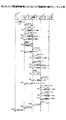
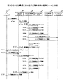
以上説明した第3のジョブ関連情報例の場合のジョブ登録時の動作を、図42のシーケンス図を用いて説明する。なお、このシーケンス図は、図34で示したシーケンス図のステップS101からステップS108までの処理と、ステップS501からステップS508までの処理が同じなので説明を省略する。 The operation at the time of job registration in the case of the third job related information example described above will be described with reference to the sequence diagram of FIG. In this sequence diagram, the processing from step S101 to step S108 and the processing from step S501 to step S508 in the sequence diagram shown in FIG.
ステップS509で、プリンタアプリ20は、印刷制御モジュール23に印刷処理要求を通知する。このとき、親ジョブのジョブ関連情報と、親ジョブのジョブIDは通知されない。印刷モジュール23は、ステップS510でジョブの生成を行い、ステップS511でプリンタアプリ20に子ジョブ生成を通知する。次のステップS512で、プリンタアプリ20は、ジョブIDをキューに追加する。そして、ステップS513で印刷制御モジュール23は、ジョブ情報を保存する。次のステップS514で、印刷制御モジュール23は、ジョブIDをキューから取得する。
In step S509, the
印刷制御モジュール23は、ステップS515で、メモリ管理モジュール30にジョブ情報の取得を要求する。メモリ管理モジュール30は、ステップS516で、印刷制御モジュール23にジョブ情報を通知する。
In step S515, the
ステップS517は、印刷制御モジュール23の処理の実行である。ステップS518で印刷制御モジュール23は、プロッタハンドラ27にプロット要求を通知する。ステップS519で、プロッタハンドラ27は、ジョブの生成を行う。
Step S517 is execution of processing of the
ステップS520で、プロッタハンドラ27は、印刷制御モジュール23に、ジョブIDとともに子ジョブの生成を通知する。ステップS521で、印刷制御モジュール23は、プリンタアプリ20に子孫ジョブの生成を通知する。このとき、親ジョブIDと子ジョブIDも通知される。
In step S520, the
ステップS522で、プロッタハンドラ27は、ジョブIDをキューに追加し、ステップS523で、ジョブ情報を保存する。ステップS524で、プロッタハンドラ27は、ジョブIDをキューから取得する。ステップS525で、プロッタハンドラ27は、メモリ管理モジュール30にジョブ情報の取得を要求する。ステップS526で、メモリ管理モジュール30は、プロッタハンドラ27にジョブ情報を通知する。
In step S522, the
プロッタハンドラ27は、ステップS527で、プロットを実行する。プロッタハンドラ27は、印刷制御モジュール23に、ステップS528で、プロット終了を通知する。印刷制御モジュール23は、ステップS529で、プリンタアプリ20に印刷終了を通知する。プリンタアプリ20は、ステップS530で、ユーザ160に印刷終了を通知(表示)する。
The
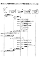
次に、図43を用いて、ジョブ参照時の動作シーケンスを説明する。なお、このシーケンス図は、図35で示したシーケンス図でのステップのうち、2つのステップ以外は同じであるので、異なるステップ以外の説明は省略する。 Next, an operation sequence at the time of job reference will be described with reference to FIG. Note that this sequence diagram is the same as the sequence diagram shown in FIG. 35 except for two steps, and thus the description other than the different steps will be omitted.
異なるステップは、図35におけるステップS203とステップS204であり、図43では、それぞれステップS603とステップS604に対応する。図35の場合、検索の対象は、末端ジョブであったが、図43では、検索の対象が根幹ジョブとなる。 The different steps are step S203 and step S204 in FIG. 35, and correspond to step S603 and step S604 in FIG. 43, respectively. In FIG. 35, the search target is the end job, but in FIG. 43, the search target is the basic job.
次に、第4のジョブ関連情報例について、図44を用いて説明する。図44に示されるジョブ関連情報は、ジョブが全ての子ジョブのジョブIDを持っているものである。 Next, a fourth job related information example will be described with reference to FIG. The job-related information shown in FIG. 44 is that the job has job IDs of all child jobs.
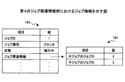
具体的に、図45に示されるジョブ情報を用いて説明する。図45には、ジョブ情報163と、ジョブ関連情報164とが示されている。ジョブ情報163に示されるように、このジョブ情報は、図31に示されているジョブ1のジョブ情報である。
Specifically, description will be made using the job information shown in FIG. FIG. 45
ジョブ関連情報164には、項目に2つの「子ジョブのジョブID」があり、それぞれ値が「2」、「3」となっている。実際に、ジョブ1の子ジョブはジョブ2とジョブ3である。
In the job
このように、ジョブ関連情報が子ジョブのジョブIDのみであれば、ジョブ情報の情報量を抑えることが可能となる。この場合、ジョブ管理モジュールが全ジョブにアクセスする仕組みが必要となる。 Thus, if the job related information is only the job ID of the child job, the information amount of the job information can be suppressed. In this case, a mechanism is required for the job management module to access all jobs.
以上説明した第4のジョブ関連情報例の場合の処理を、図46のシーケンス図を用いて説明する。なお、このシーケンス図は、図42で示したシーケンス図のステップS521の処理を行わないこと以外は、処理が同じなので説明を省略する。これは、第4のジョブ関連情報は、子孫ジョブを必要としないので、子孫ジョブの生成を通知する図42のステップS521の処理は不要となるからである。 The processing in the case of the fourth job related information example described above will be described with reference to the sequence diagram of FIG. This sequence diagram is the same as the sequence diagram except that step S521 in the sequence diagram shown in FIG. This is because the fourth job-related information does not require a child job, and therefore the process of step S521 in FIG. 42 for notifying generation of a child job is not necessary.
ジョブ参照時の動作シーケンスは、図39と同じであるため、説明を省略する。 The operation sequence at the time of referring to the job is the same as that in FIG.
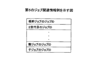
次に、第1、4のジョブ関連情報を組み合わせた第5のジョブ関連情報例について、図47を用いて説明する。図47に示されるジョブ関連情報は、ジョブが全ての先祖のジョブIDと、全ての子ジョブのジョブIDからなる。 Next, a fifth job-related information example in which the first and fourth job-related information are combined will be described with reference to FIG. The job related information shown in FIG. 47 includes job IDs of all ancestors of jobs and job IDs of all child jobs.
具体的に、図48に示されるジョブ情報を用いて説明する。図48には、ジョブ情報166と、ジョブ関連情報169とが示されている。ジョブ情報166に示されるように、このジョブ情報は、図31に示されているジョブ4のジョブ情報である。
Specifically, description will be made using the job information shown in FIG. FIG. 48 shows job information 166 and job
ジョブ関連情報169には、項目に「根幹ジョブのジョブID」と、「親ジョブのジョブID」と、「子ジョブのジョブID」があり、それぞれ値が「1」、「2」、「7」となっている。実際に、ジョブ4の根幹ジョブはジョブ1であり、親ジョブはジョブ2であり、子ジョブは、ジョブ7である。
In the job-related
このようなジョブ関連情報であれば、ジョブ管理モジュールは末端ジョブの情報を取得するだけで、ジョブ構造テーブルが作成できる。また、アプリ層、サービス層、ハンドラ層の各プログラムは、親のジョブ関連情報に親のジョブIDを追記するだけなので、ジョブ生成時にジョブ関連情報を作成するのが容易となる。さらに、子ジョブのジョブIDの項目に値がない場合は末端ジョブであるので、末端ジョブの検索が子ジョブのジョブIDの項目に値が入っているかどうかを見ることで可能となる。なお、値が入っていないとは、実質的な値が入っていないことであり、例えばNULLもしくは0xffffなど、設計でよく用いられる値が入っていることであっても良い。なお、ジョブを生成するモジュールは、親ジョブを生成したモジュールに子ジョブのジョブIDを通知する必要がある。 With such job-related information, the job management module can create a job structure table simply by acquiring end job information. In addition, since each program of the application layer, service layer, and handler layer only adds the parent job ID to the parent job related information, it is easy to create job related information when generating a job. Further, if there is no value in the job ID item of the child job, it is a terminal job, and therefore, it becomes possible to search for the terminal job by checking whether or not a value is entered in the job ID item of the child job. It should be noted that the absence of a value means that a substantial value is not contained, and may include a value often used in design, such as NULL or 0xffff. Note that the module that generates the job needs to notify the job ID of the child job to the module that generated the parent job.
以上説明した第5のジョブ関連情報例の場合のジョブ登録時の動作を、図49のシーケンス図を用いて説明する。なお、このシーケンス図は、図34で示したシーケンス図と一部異なるので、その異なる部分を説明することにする。 The operation at the time of job registration in the case of the fifth job related information example described above will be described with reference to the sequence diagram of FIG. Since this sequence diagram is partially different from the sequence diagram shown in FIG. 34, the different parts will be described.
ステップS809は、ステップSS109に対応するが、親ジョブ用のジョブ関連情報のみが通知される。また、ステップS810でジョブを生成した後、ステップS811で、プリンタアプリ20に子ジョブの生成を通知する処理が追加される。
Step S809 corresponds to step SS109, but only the job related information for the parent job is notified. In addition, after the job is generated in step S810, processing for notifying the
またステップS818のプロット要求では、親ジョブのジョブ関連情報のみが通知される。さらに、ステップS819のジョブの生成後に、プロッタハンドラ27から印刷制御モジュール23へ子ジョブの生成が通知される。
In the plot request in step S818, only the job related information of the parent job is notified. Further, after the job is generated in step S819, the
ジョブ参照時の動作シーケンスは、図35と同じであるため、説明を省略する。 The operation sequence when referring to the job is the same as that shown in FIG.
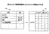
次に、第2、3のジョブ関連情報を組み合わせた第6のジョブ関連情報例について、図50を用いて説明する。図50に示されるジョブ関連情報は、親ジョブのジョブIDと、全ての子孫ジョブのジョブIDからなる。 Next, a sixth job related information example in which the second and third job related information are combined will be described with reference to FIG. The job related information shown in FIG. 50 includes the job ID of the parent job and the job IDs of all descendant jobs.
具体的に、図51に示されるジョブ情報を用いて説明する。図51には、ジョブ情報170と、ジョブ関連情報171とが示されている。ジョブ情報170に示されるように、このジョブ情報は、図31に示されているジョブ1のジョブ情報である。
Specifically, description will be made using the job information shown in FIG. FIG. 51
ジョブ関連情報171には、項目に「子ジョブ」と、「親ジョブ」がある。子ジョブで示されるジョブIDの親ジョブのジョブIDが親ジョブの欄に記載される。
The job
実際、ジョブ1は根幹ジョブであるので、親ジョブは存在せず、ジョブ2、3の親ジョブはジョブ1であり、ジョブ4、5の親ジョブはジョブ2であり、ジョブ6の親ジョブはジョブ3であり、ジョブ7の親ジョブは、ジョブ4である。
Actually, since
この第6のジョブ関連情報では、根幹ジョブの情報を取得するだけで、ジョブ構造テーブルが作成できる。なお、根幹ジョブのジョブ関連情報には、親ジョブのジョブIDの項目に値が入っていないことから、根幹ジョブを判別することができる。 With this sixth job-related information, a job structure table can be created simply by acquiring information on the basic job. Since the job-related information of the basic job does not include a value in the job ID item of the parent job, the basic job can be determined.
以上説明した第6のジョブ関連情報例の場合のジョブ登録時の動作を、図52のシーケンス図を用いて説明する。なお、このシーケンス図は、図34で示したシーケンス図と一部異なるので、その異なる部分を説明することにする。 The operation at the time of job registration in the case of the sixth job related information example described above will be described with reference to the sequence diagram of FIG. Since this sequence diagram is partially different from the sequence diagram shown in FIG. 34, the different parts will be described.
ステップS909は、ステップS109に対応するが、親ジョブのジョブIDのみ通知される。また、ステップS910でジョブを生成した後、ステップS911で、プリンタアプリ20に子ジョブの生成を通知する処理が追加される。また、ステップS918は、ステップS117に対応するが、親ジョブのジョブIDのみ通知される。さらに、ステップS920で子ジョブの生成通知後、ステップS921で、印刷制御モジュール23からプリンタアプリ20に子孫ジョブの生成が通知される処理が加わる。
Step S909 corresponds to step S109, but only the job ID of the parent job is notified. Further, after the job is generated in step S910, a process for notifying the
ジョブ参照時の動作シーケンスは、図43と同じであるため、説明を省略する。 The operation sequence at the time of referring to the job is the same as that in FIG.
次に、ジョブ管理モジュール26で一括管理する第7のジョブ関連情報例について、図53を用いて説明する。
Next, a seventh job related information example collectively managed by the
第7のジョブ関連情報例は、各モジュールでの処理において子ジョブが派生した場合は、各モジュールがジョブ管理モジュールに派生した子ジョブのジョブIDと親のジョブIDの対応を通知することで生成される。ジョブ管理モジュール26は、全ジョブの対応関係を保持しており、表示アプリにジョブ構造を表示させる場合はその情報を表示アプリに通知するようになっている。
The seventh example of job-related information is generated by notifying the correspondence between the job ID of the derived child job and the parent job ID to the job management module when a child job is derived in the processing of each module. Is done. The
図53には、ジョブの関係図172、173、174と、プリンタアプリ20と、印刷制御モジュール23と、ジョブ管理モジュール26とが示されている。
FIG. 53 shows job relationship diagrams 172, 173, and 174, the
関係図172は、プリンタアプリ20が生成したジョブの関係図である。関係図173は、印刷制御モジュール23が生成したジョブの関係図である。関係図174は、関係図172、173に基づき、ジョブ管理モジュール26が生成した関係図である。
A relationship diagram 172 is a relationship diagram of jobs generated by the
関係図172で示されているジョブの関係と、関係図173で示されているジョブの関係が、関係図174に反映されていることが分かる。この場合、ジョブ情報は、ジョブ関連情報を持たなくても良い。 It can be seen that the job relationship shown in the relationship diagram 172 and the job relationship shown in the relationship diagram 173 are reflected in the relationship diagram 174. In this case, the job information may not have job related information.
以上説明した第7のジョブ関連情報例の場合のジョブ登録時の動作を、図54のシーケンス図を用いて説明する。なお、このシーケンス図は、図34で示したシーケンス図と一部異なるので、その異なる部分を説明することにする。 The operation at the time of job registration in the case of the seventh job related information example described above will be described with reference to the sequence diagram of FIG. Since this sequence diagram is partially different from the sequence diagram shown in FIG. 34, the different parts will be described.
ステップS1002のプリンタアプリ20がジョブを生成する処理の後に、ステップS1003と、ステップS1004の処理が追加される。ステップS1003の処理は、プリンタアプリ20からジョブ管理モジュール26へのジョブ生成の通知である。このとき、親ジョブIDと子ジョブIDが通知される。また、ステップS1004は、ジョブ管理モジュール26によるジョブ構造テーブルの更新である。
Steps S1003 and S1004 are added after the
ステップS1011は、ステップS109に対応するが、親ジョブのジョブIDのみの通知となる。 Step S1011 corresponds to step S109, but only the job ID of the parent job is notified.
ステップS1012の印刷制御モジュール23がジョブを生成する処理の後に、ステップS1013と、ステップS1014の処理が追加される。ステップS1013の処理は、印刷制御モジュール23からジョブ管理モジュール26へのジョブ生成の通知である。このとき、親ジョブIDと子ジョブIDが通知される。また、ステップS1014は、ジョブ管理モジュール26によるジョブ構造テーブルの更新である。
Steps S1013 and S1014 are added after the
ステップS1021は、ステップS117に対応するが、親ジョブのジョブIDのみの通知となる。 Step S1021 corresponds to step S117, but only the job ID of the parent job is notified.
ステップS1022のプロッタハンドラ27がジョブを生成する処理の後に、ステップS1023と、ステップS1024の処理が追加される。ステップS1023の処理は、プロッタハンドラ27からジョブ管理モジュール26へのジョブ生成の通知である。このとき、親ジョブIDと子ジョブIDが通知される。また、ステップS1024は、ジョブ管理モジュール26によるジョブ構造テーブルの更新である。
After the process in which the
次に、図55を用いて、ジョブ参照時の動作シーケンスを説明する。図55は、ユーザ160と、オペパネアプリ161と、ジョブ管理モジュール26と、プリンタアプリ20と、メモリ管理モジュール30との間で行われる処理を示している。
Next, an operation sequence at the time of job reference will be described with reference to FIG. FIG. 55 shows processing performed among the
ステップS1101で、オペパネアプリ161は、ユーザ160からジョブ参照要求を通知される。ステップS1102で、オペパネアプリ161は、ジョブ管理モジュール26にジョブ一覧要求を通知する。ステップS1103で、ジョブ管理モジュール26は、オペパネアプリ161にジョブ一覧を通知する。オペパネアプリ161は、ステップS1104で、ユーザ160に、ジョブ一覧を通知(表示)する。ステップS1105で、オペパネアプリ161は、ユーザ160からジョブ情報を要求される。ステップS1106で、オペパネアプリ161は、ジョブ管理モジュール26にジョブ情報の取得を要求する。
In step S1101, the
ジョブ管理モジュール26は、ステップS1107で、メモリ管理モジュール30に、ジョブ情報の取得を要求する。メモリ管理モジュール30は、ステップS1108で、ジョブ管理モジュール26にジョブ情報を通知する。
In step S1107, the
ジョブ管理モジュール26は、ステップS1109で、プリンタアプリ20に、キューの順番取得を要求する。プリンタアプリ20は、ステップS1110で、ジョブ管理モジュール26にキューの順番を通知する。ジョブ管理モジュール26は、ステップS1111で、オペパネアプリ161にジョブ情報を通知する。ステップS1112で、オペパネアプリ161は、ユーザ160にジョブ情報を通知(表示)する。
In step S1109, the
次に、ソフトウェアの構成が図30で説明した構成であり、ジョブ関連情報が図32に示したジョブ関連情報の場合の処理について説明する。図30における構成は、ジョブ情報は各アプリ層、サービス層のモジュールが各自のメモリ空間に保持する構成である。この構成でのジョブ登録時の動作シーケンスを、図56を用いて説明する。 Next, processing when the software configuration is the configuration described with reference to FIG. 30 and the job related information is the job related information illustrated in FIG. 32 will be described. The configuration in FIG. 30 is a configuration in which job information is stored in its own memory space by each application layer and service layer module. An operation sequence at the time of job registration in this configuration will be described with reference to FIG.
図56には、ユーザ160と、プリンタアプリ20と、印刷制御モジュール23と、プロッタハンドラ27との間で行われる処理を示している。
FIG. 56 shows processing performed among the
ステップS1201で、プリンタアプリ20は、ユーザ160から印刷要求を通知される。プリンタアプリ20は、ステップS1202で、ジョブの生成を行い、ステップS1203で、ジョブIDをキューに追加する。ステップS1204で、プリンタアプリ20は、キューからジョブIDを取得し、ステップS1205で、処理を実行する。
In step S <b> 1201, the
ステップS1206で、プリンタアプリ20は、印刷制御モジュール23に印刷処理要求を通知する。このとき、親ジョブのジョブ関連情報と、親ジョブのジョブIDも通知される。印刷モジュール23は、ステップS1207でジョブの生成を行い、ステップS1208でジョブIDをキューに追加する。そして、印刷制御モジュール23は、ステップS1209でジョブIDをキューから取得し、ステップS1210で処理を実行する。
In step S1206, the
ステップS1211で印刷制御モジュール23は、プロッタハンドラ27にプロット要求を通知する。このとき、親ジョブのジョブ関連情報と親ジョブIDも通知される。
In step S1211, the
ステップS1212で、プロッタハンドラ27は、ジョブの生成を行う。ステップS1213で、プロッタハンドラ27は、ジョブIDをキューに追加し、ステップS1214でジョブIDをキューから取得する。
In step S1212, the
プロッタハンドラ27は、ステップS1215で、プロットを実行する。プロッタハンドラ27は、印刷制御モジュール23に、ステップS1216で、プロット終了を通知する。印刷制御モジュール23は、ステップS1217で、プリンタアプリ20に印刷終了を通知する。プリンタアプリ20は、ステップS1218で、ユーザ160に印刷終了を通知(表示)する。
In step S1215, the
次に、図57を用いて、ジョブ参照時の動作シーケンスを説明する。図57は、ユーザ160と、オペパネアプリ161と、ジョブ管理モジュール26と、プリンタアプリ20と、印刷制御モジュール23と、プロッタハンドラ27との間で行われる処理を示している。
Next, an operation sequence at the time of job reference will be described with reference to FIG. FIG. 57 shows processing performed among the
ステップS1301で、オペパネアプリ161は、ユーザ160からジョブ参照要求を通知される。ステップS1302で、オペパネアプリ161は、ジョブ管理モジュール26にジョブ一覧要求を通知する。
In step S1301, the
ジョブ管理モジュール26は、ステップS1303で、プリンタアプリ20にジョブ情報の取得を要求する。ステップS1304で、プリンタアプリ20は、ジョブ管理モジュール26にジョブ情報を通知する。
In step S1303, the
ジョブ管理モジュール26は、ステップS1305で、印刷制御モジュール23にジョブ情報の取得を要求する。ステップS1306で、印刷制御モジュール23は、ジョブ管理モジュール26にジョブ情報を通知する。
In step S1305, the
ジョブ管理モジュール26は、ステップS1307で、プロッタハンドラ27にジョブ情報の取得を要求する。ステップS1308で、プロッタハンドラ27は、ジョブ管理モジュール26にジョブ情報を通知する。
In step S1307, the
ステップS1309で、ジョブ管理モジュール26は、ジョブ一覧の作成を行う。ステップS1310で、ジョブ管理モジュール26は、オペパネアプリ161にジョブ一覧を通知する。オペパネアプリ161は、ステップS1311で、ユーザ160に、ジョブ一覧を通知(表示)する。
In step S1309, the
ステップS1312で、オペパネアプリ161は、ユーザ160からジョブ情報を要求される。ステップS1313で、オペパネアプリ161は、ジョブ管理モジュール26にジョブ情報の取得を要求する。ジョブ管理モジュール26は、ステップS1314で、プリンタアプリ20にジョブ情報の取得を要求する。プリンタアプリ20は、ステップS1315で、ジョブ管理モジュール26にジョブ情報を通知する。
In step S1312, the
ステップS1316で、ジョブ管理モジュール26は、プリンタアプリ20に、キューの順番取得を要求する。プリンタアプリ20は、ステップS1317で、ジョブ管理モジュール26にキューの順番を通知する。ジョブ管理モジュール26は、ステップS1318で、オペパネアプリ161にジョブ情報を通知する。ステップS1319で、オペパネアプリ161は、ユーザ160にジョブ情報を通知(表示)する。
In step S1316, the
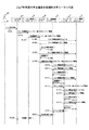
次に、図58を用いて、ユーザからジョブを中止された場合の処理について説明する。ステップS1401で、オペパネアプリ161は、ユーザ160からジョブの中止を通知される。オペパネアプリ161は、ステップS1402で、ジョブ管理モジュール26にジョブの中止を通知する。ジョブ管理モジュール26は、ステップS1403で、プリンタアプリ20に印刷要求の中止を通知する。
Next, processing when a job is canceled by the user will be described with reference to FIG. In step S1401, the
プリンタアプリ20は、ステップS1404でメモリ管理モジュール30にジョブ情報の取得を要求し、ステップS1405で、中止処理を行う。プリンタアプリ20は、ステップS1406で、印刷制御モジュール23に印刷処理の中止を通知する。
The
印刷制御モジュール23は、ステップS1407で、メモリ管理モジュール30にジョブ情報の取得を要求し、ステップS1408で、中止処理を行う。印刷制御モジュール23は、ステップS1409で、プロッタハンドラ27にプロットの中止を通知する。プロッタハンドラ27は、ステップS1410で、メモリ管理モジュール30にジョブ情報の取得を要求し、ステップS1411で、中止処理を行う。
In step S1407, the
次に、図59を用いて、ユーザからジョブの再実行を要求された場合の処理について説明する。ステップS1501で、オペパネアプリ161は、ユーザ160からジョブの再実行が通知される。オペパネアプリ161は、ステップS1502で、ジョブ管理モジュール26にジョブの再実行を通知する。ジョブ管理モジュール26は、ステップS1503で、プリンタアプリ20に印刷再要求を通知する。プリンタアプリ20は、ステップS1504で、メモリ管理モジュール30にジョブ情報の取得を要求する。メモリ管理モジュール30は、ステップS1505で、プリンタアプリ20にジョブ情報を通知する。
Next, with reference to FIG. 59, a description will be given of processing in the case where the user requests job re-execution. In step S1501, the
プリンタアプリ20は、ステップS1506で、ジョブ情報を変更し、ステップS1507で、メモリ管理モジュール30にジョブ情報を通知することで、ジョブ情報を保存する。ステップS1508は、プリンタアプリ20の処理の実行である。
The
プリンタアプリ20は、ステップS1509で、印刷制御モジュール23に印刷処理の再実行を通知する。印刷制御モジュール23は、ステップS1510で、メモリ管理モジュール30にジョブ情報の取得を要求する。メモリ管理モジュール30は、ステップS1511で、印刷制御モジュール23にジョブ情報を通知する。印刷制御モジュール23は、ステップS1512で、ジョブ情報を変更し、ステップS1513で、メモリ管理モジュール30にジョブ情報を通知することで、ジョブ情報を保存する。ステップS1514は、印刷制御モジュール23の処理の実行である。
In step S1509, the
ステップS1515で、印刷制御モジュール23は、プロッタハンドラ27にプロット再実行を通知する。プロッタハンドラ27は、ステップS1516で、メモリ管理モジュール30にジョブ情報の取得を要求する。メモリ管理モジュール30は、ステップS1517で、印刷制御モジュール23にジョブ情報を通知する。印刷制御モジュール23は、ステップS1518で、ジョブ情報を変更し、ステップS1519で、メモリ管理モジュール30にジョブ情報を通知することで、ジョブ情報を保存する。ステップS1520は、プロッタの実行である。
In step S1515, the
プロッタハンドラ27は、印刷制御モジュール23に、ステップS1521で、プロット終了を通知する。印刷制御モジュール23は、ステップS1522で、プリンタアプリ20に印刷終了を通知する。プリンタアプリ20は、ステップS1523で、オペパネアプリ161に印刷終了を通知する。
In step S1521, the
5 アプリケーション層
7 サービス層
9 ハンドラ層
20 プリンタアプリ
21 コピーアプリ
22 FAXアプリ
23 印刷制御モジュール
24 FAX制御モジュール
25 読み取り制御モジュール
26 ジョブ管理モジュール
27 プロッタハンドラ
28 FAXユニットハンドラ
29 スキャナハンドラ
30 メモリ管理モジュール
51 スキャナ
52 プロッタ
53 オペレーションパネル
60 コントローラボード
61 CPU
62 ノースブリッジ(NB)
63 システムメモリ(MEM−P)
64 ローカルメモリ(MEM−C)
65 ハードディスク装置(HDD)
66 ASIC
67 AGP(Accelerated Graphics Port)
68 ファックスコントロールユニット(FCU)
69 G3
70 G4
71 エンジン
73 サウスブリッジ(SB)
74 NIC
75 USBデバイス
76 IEEE1394デバイス
77 セントロニクス
103 FAX送信ジョブ
104 宛先ごとのFAX送信ジョブ
110 コピー蓄積ジョブ
111 読み取りジョブ
112 プリントジョブ
113 蓄積ジョブ
114、115 プロッタジョブ
130 各プログラム
131 専用キュー
132、150、163、166、167、170 ジョブ情報
133 キュー
151、164、168、169、171 ジョブ関連情報
172、173、174 関係図
254、417 白黒プリントジョブ
255、256、258 プロッタジョブ
257、418 カラープリントジョブ
259 印刷ジョブ
271、272 ジョブ構造
400 ジョブA
401 ジョブA-A
402 ジョブA-B
403 ジョブA-A-A
404 ジョブA-A-B
405 ジョブA-B-A
410、415 プリントジョブ
411、416、432 印刷ジョブ
412、419、420、421 プロッタジョブ
430 コピージョブ
431 読み取りジョブ
433 1ページ〜10ページの印刷ジョブ
434 11ページ目の印刷ジョブ
435 12ページ〜20ページの印刷ジョブ
441 FAX送信ジョブ
442、443、444 宛先ごとのFAX送信ジョブ
450 ジョブA
451 ジョブB
452 ジョブC
453 ジョブD
500 プロセスA
501 スレッドA
502 スレッドB
503 スレッドC
505 プロセスB
506 プロセスC
507 スレッドD
508 スレッドE
601 待機中
602 実行中
603 完了
604 中断中
605 中止
606 エラー発生
5
62 North Bridge (NB)
63 System memory (MEM-P)
64 Local memory (MEM-C)
65 Hard Disk Drive (HDD)
66 ASIC
67 AGP (Accelerated Graphics Port)
68 Fax Control Unit (FCU)
69 G3
70 G4
71
74 NIC
75
401 Job A-A
402 Job AB
403 Job A-A-A
404 Job A-A-B
405 Job A-B-A
410, 415
451 Job B
452 Job C
453 Job D
500 Process A
501 Thread A
502 Thread B
503 Thread C
505 Process B
506 Process C
507 Thread D
508 Thread E
601
Claims (32)
前記1つのジョブと他のジョブとの関連を示すジョブ関連情報を、前記ジョブごとに生成するジョブ関連情報生成手段と、
前記ジョブ関連情報に基づき、任意のジョブと関連のあるジョブを検索するためのジョブ構造情報を作成するジョブ構造情報作成手段と
を有することを特徴とする画像形成装置。 In an image forming apparatus that has hardware resources used in image forming processing and executes a job related to image formation,
Job-related information generating means for generating job-related information indicating the relationship between the one job and another job for each job;
An image forming apparatus comprising: job structure information creating means for creating job structure information for searching for a job related to an arbitrary job based on the job related information.
前記ジョブのジョブ構造情報を作成するためのジョブ関連情報を生成するジョブ関連情報生成段階と、
前記ジョブ関連情報に基づきジョブ構造情報を作成するジョブ構造情報作成段階と
を有することを特徴とするジョブ管理方法。 A job management method for managing a job in an image forming apparatus that has a hardware resource used in image forming processing and executes a job related to image formation,
A job-related information generation stage for generating job-related information for creating job structure information of the job;
And a job structure information creating step of creating job structure information based on the job related information.
Priority Applications (2)
| Application Number | Priority Date | Filing Date | Title |
|---|---|---|---|
| JP2005057889A JP2005295514A (en) | 2004-03-08 | 2005-03-02 | Image forming apparatus and job management method |
| US11/072,593 US20050206913A1 (en) | 2004-03-08 | 2005-03-07 | Image forming apparatus, job managing method, electronic device, job displaying method, and job displaying program |
Applications Claiming Priority (3)
| Application Number | Priority Date | Filing Date | Title |
|---|---|---|---|
| JP2004064048 | 2004-03-08 | ||
| JP2004064049 | 2004-03-08 | ||
| JP2005057889A JP2005295514A (en) | 2004-03-08 | 2005-03-02 | Image forming apparatus and job management method |
Publications (1)
| Publication Number | Publication Date |
|---|---|
| JP2005295514A true JP2005295514A (en) | 2005-10-20 |
Family
ID=35327892
Family Applications (1)
| Application Number | Title | Priority Date | Filing Date |
|---|---|---|---|
| JP2005057889A Pending JP2005295514A (en) | 2004-03-08 | 2005-03-02 | Image forming apparatus and job management method |
Country Status (1)
| Country | Link |
|---|---|
| JP (1) | JP2005295514A (en) |
Cited By (1)
| Publication number | Priority date | Publication date | Assignee | Title |
|---|---|---|---|---|
| JP2008028719A (en) * | 2006-07-21 | 2008-02-07 | Fuji Xerox Co Ltd | Image forming apparatus and program |
-
2005
- 2005-03-02 JP JP2005057889A patent/JP2005295514A/en active Pending
Cited By (1)
| Publication number | Priority date | Publication date | Assignee | Title |
|---|---|---|---|---|
| JP2008028719A (en) * | 2006-07-21 | 2008-02-07 | Fuji Xerox Co Ltd | Image forming apparatus and program |
Similar Documents
| Publication | Publication Date | Title |
|---|---|---|
| EP1727035B1 (en) | Print control program, method of controlling printing apparatus and print control unit | |
| JP5178227B2 (en) | Printing apparatus, document management apparatus, and computer program | |
| JP5383254B2 (en) | Information processing apparatus, control method therefor, and program | |
| JP4420421B2 (en) | Information processing apparatus and control method thereof | |
| JP5116323B2 (en) | Information processing apparatus, information processing method, and computer program | |
| JP5178293B2 (en) | Workflow execution device, workflow execution method, and computer program | |
| JP2007104063A (en) | Data transmission apparatus, control method therefor, and image input / output apparatus | |
| JP4690355B2 (en) | Information processing apparatus and information processing program | |
| JP2019089287A (en) | Image forming apparatus, control method of image forming apparatus, and program | |
| JP4714483B2 (en) | Electronic device, job display method, and job display program | |
| JP4110147B2 (en) | Information leakage prevention method, information processing apparatus and driver program for realizing the method | |
| JP4977113B2 (en) | Printing system, bibliographic information server, printing apparatus, method and program | |
| JP6238640B2 (en) | Image forming apparatus, information processing method, and program | |
| JP2008165738A (en) | Job processing method, image processing system, and program | |
| JP4931237B2 (en) | Document management system, document management method, computer program, and storage medium | |
| JP2005295514A (en) | Image forming apparatus and job management method | |
| JP2007200140A (en) | Document authority management apparatus, document authority management system, document authority management method, and computer program | |
| JP4078292B2 (en) | Information processing apparatus, information processing method and program, and computer-readable storage medium | |
| JP6155802B2 (en) | Image forming apparatus, image forming system, control method thereof, and program | |
| JP7005139B2 (en) | Image processing device and its control method, printing system, program | |
| JP2007274583A (en) | Management system, image processing apparatus, management apparatus, control method therefor, and program | |
| JP5448538B2 (en) | Image processing apparatus, image processing method, image processing program, and image processing system | |
| JP2004357274A (en) | Image processing apparatus, image processing method, and image processing program | |
| JP2004334287A (en) | Electronic document printing device | |
| JP2020069688A (en) | Image forming apparatus, control method of image forming apparatus, and program |
Legal Events
| Date | Code | Title | Description |
|---|---|---|---|
| A621 | Written request for application examination |
Free format text: JAPANESE INTERMEDIATE CODE: A621 Effective date: 20070806 |
|
| A977 | Report on retrieval |
Free format text: JAPANESE INTERMEDIATE CODE: A971007 Effective date: 20090626 |
|
| A131 | Notification of reasons for refusal |
Free format text: JAPANESE INTERMEDIATE CODE: A131 Effective date: 20090714 |
|
| A521 | Written amendment |
Free format text: JAPANESE INTERMEDIATE CODE: A523 Effective date: 20090904 |
|
| A131 | Notification of reasons for refusal |
Free format text: JAPANESE INTERMEDIATE CODE: A131 Effective date: 20090929 |
|
| A521 | Written amendment |
Free format text: JAPANESE INTERMEDIATE CODE: A523 Effective date: 20091030 |
|
| A02 | Decision of refusal |
Free format text: JAPANESE INTERMEDIATE CODE: A02 Effective date: 20091124 |