JP2005295710A - motor - Google Patents
motor Download PDFInfo
- Publication number
- JP2005295710A JP2005295710A JP2004108394A JP2004108394A JP2005295710A JP 2005295710 A JP2005295710 A JP 2005295710A JP 2004108394 A JP2004108394 A JP 2004108394A JP 2004108394 A JP2004108394 A JP 2004108394A JP 2005295710 A JP2005295710 A JP 2005295710A
- Authority
- JP
- Japan
- Prior art keywords
- coil
- yoke
- motor
- rotor
- pair
- Prior art date
- Legal status (The legal status is an assumption and is not a legal conclusion. Google has not performed a legal analysis and makes no representation as to the accuracy of the status listed.)
- Pending
Links
- 230000003287 optical effect Effects 0.000 claims abstract description 28
- 230000002093 peripheral effect Effects 0.000 claims abstract description 19
- 238000004804 winding Methods 0.000 abstract description 11
- 230000001681 protective effect Effects 0.000 description 4
- 239000000470 constituent Substances 0.000 description 2
- 238000005192 partition Methods 0.000 description 2
- 239000000758 substrate Substances 0.000 description 2
- 239000000696 magnetic material Substances 0.000 description 1
- 238000000034 method Methods 0.000 description 1
Images

Landscapes
- Lens Barrels (AREA)
- Iron Core Of Rotating Electric Machines (AREA)
Abstract
【課題】 ステータのコイル巻線形状が安定化し、コイルの巻崩れの恐れが少ないモータを提供する。
【解決手段】 本発明に係るモータMは、複数の磁極を着磁したロータ1と、磁極部4a1,4a2がロータ1の外周面に近接して位置するヨーク4及びヨーク4に巻回されるコイル5を備えたステータ3とから構成される。ヨーク4は対向する一対の脚部4a,4aとこれを連結する連結部4bから構成されるH字形状をなし、コイル5がヨークの連結部4bに巻回されている。コイル5は、その外周部が脚部4aの外端部とほぼ等しい位置にあることが好ましい。また、本発明に係るモータMは、例えば、光学モジュールのレンズ系を移動させる駆動部に組み込まれる。
【選択図】 図1PROBLEM TO BE SOLVED: To provide a motor in which a coil winding shape of a stator is stabilized and there is little risk of coil collapse.
A motor M according to the present invention is wound around a rotor 1 magnetized with a plurality of magnetic poles, and a yoke 4 and a yoke 4 in which magnetic pole portions 4a1 and 4a2 are located close to the outer peripheral surface of the rotor 1. And a stator 3 having a coil 5. The yoke 4 has an H-shape composed of a pair of opposing leg portions 4a, 4a and a connecting portion 4b that connects them, and a coil 5 is wound around the connecting portion 4b of the yoke. It is preferable that the outer peripheral part of the coil 5 is in a position substantially equal to the outer end part of the leg part 4a. In addition, the motor M according to the present invention is incorporated in, for example, a driving unit that moves the lens system of the optical module.
[Selection] Figure 1
Description
本発明はコイルの巻崩れを防止したモータに関する。 The present invention relates to a motor that prevents coil collapse.
近年、微小なカメラを搭載した携帯電話、ノート型パソコン、携帯型テレビ電話等の携帯用電子機器が広く普及している。これらの携帯用電子機器には、光学系に対して精度良く位置決めする小型のモータが組み込まれている。モータは、一般にロータとヨーク及びコイルを備えたステータとから構成される。かかるモータとしては、従来から数多くの提案がなされている(例えば、特許文献1)。
特許文献1のモータでは、U字状ないしはコ字状ヨークの外側の脚部にコイル枠が挿着され、コイル枠内にコイルが巻回されている。この特許文献1は、コイル枠を設けているため部品点数が多くなるという難点がある。そこで、U字状ヨークにおける外側の脚部または中央部にコイルを直に巻き付けたステータ構造が考えられる。
2. Description of the Related Art In recent years, portable electronic devices such as mobile phones equipped with minute cameras, notebook computers, and portable videophones have become widespread. These portable electronic devices incorporate a small motor that accurately positions the optical system. The motor is generally composed of a rotor and a stator having a yoke and a coil. As such a motor, many proposals have been conventionally made (for example, Patent Document 1).
In the motor of
例えば、後者のステータ構造を採用したモータを図6に示す。
このモータは、複数の磁極を着磁したロータaの外周面に近接して、U字状ヨークbの中央部に導線を直に巻き付けたコイルc及び上記ヨークbから構成される一対のステータd,dの磁極部が配置され、更にロータaの外周面に近接して上記ヨークb開口部内に補助ヨークeが配置されている。なお、モータは、ロータ軸f及びそのボス部gを備えている。
This motor is close to the outer peripheral surface of a rotor a magnetized with a plurality of magnetic poles, and a pair of stators d comprising a coil c and a yoke b in which a conducting wire is wound directly around the central portion of a U-shaped yoke b. , D are disposed, and an auxiliary yoke e is disposed in the opening of the yoke b in the vicinity of the outer peripheral surface of the rotor a. The motor includes a rotor shaft f and a boss portion g thereof.
図6に示すモータにおいては、U字状ヨークの中央部に導線を直に巻き付けることによりステータが形成される。そのため、ヨークの開口部内に巻回されるコイル両端面は、ヨークの一対の脚部間で支持されるので巻線形状が安定化する。しかし、図6に示すステータ構造では、特許文献1の構成部材であるコイル枠が存在しないため、ヨークの外側に巻回されるコイル部分は、単に先に巻回された導線上に支持されるだけであるので、巻線形状にむらが生じやすく、場合によっては巻崩れの懸念がある。従って、図6(A)の破線Aで示すように、コイル巻線全体が巻崩れする懸念がある。この点は、U字状ヨークの脚部に導線を直に巻き付けた場合も同様である。
In the motor shown in FIG. 6, a stator is formed by winding a conducting wire directly around the central portion of the U-shaped yoke. Therefore, both end faces of the coil wound in the opening of the yoke are supported between the pair of leg portions of the yoke, so that the winding shape is stabilized. However, in the stator structure shown in FIG. 6, there is no coil frame that is a constituent member of
そこで、本発明の目的は、上述の従来技術の問題点を解消しようとするものであり、ヨークに巻回されるコイルの巻線形状が安定化し、コイルの巻崩れの恐れの少ないモータを提供することにある。 SUMMARY OF THE INVENTION Accordingly, an object of the present invention is to solve the above-mentioned problems of the prior art, and provide a motor that stabilizes the winding shape of a coil wound around a yoke and reduces the risk of coil collapse. There is to do.
本発明に係るモータは、複数の磁極を着磁したロータと、磁極部がロータの外周面に近接して位置するヨーク及び該ヨークに巻回された導線により形成されるコイルを備えたステータとから構成され、前記ヨークは対向する一対の脚部とこれを連結する連結部から構成されるH字形状をなし、前記コイルが連結部の上にかつ一対の脚部の間に巻回されている。 A motor according to the present invention includes a rotor having a plurality of magnetic poles magnetized, a yoke having a magnetic pole portion positioned close to the outer peripheral surface of the rotor, and a coil formed by a conductive wire wound around the yoke; The yoke has an H-shape composed of a pair of opposed leg portions and a connecting portion that connects the yoke, and the coil is wound on the connecting portion and between the pair of leg portions. Yes.
前記コイルは、例えばその導線がヨークの連結部に直に巻回されて構成されている。
また、前記ヨークに巻回されるコイルの外周部が、脚部の外端部とほぼ等しい位置にあることが好ましい。
The coil is configured, for example, by winding a conducting wire directly around a connecting portion of a yoke.
Moreover, it is preferable that the outer peripheral part of the coil wound by the said yoke exists in the position substantially equal to the outer end part of a leg part.
本発明に係る光学モジュールは、上述のモータがレンズ系を移動させる駆動部に組み込まれている。
前記レンズ系を包含する光学ユニットの外周部に一対の前記ステータが配置され、前記一対のステータは組み合わされてく字状を構成し、かつ、各ステータは前記光学ユニットの外周に沿う向きに配置されている。
The optical module according to the present invention is incorporated in a driving unit in which the above-described motor moves the lens system.
A pair of stators are arranged on the outer peripheral portion of the optical unit including the lens system, the pair of stators are combined to form a square shape, and each stator is arranged in a direction along the outer periphery of the optical unit. ing.
本発明に係るモータは、H字状ヨークにおける対向する一対の脚部を連結する連結部にステータコイルが巻回されているので、ステータコイルがH字状ヨークの一対の脚部間に巻回・支持される。そのため、コイルの巻線形状が安定化して、ヨークに巻き付けられるコイルの巻崩れが防止される。 In the motor according to the present invention, the stator coil is wound between the pair of leg portions of the H-shaped yoke because the stator coil is wound around the connecting portion that connects the pair of opposed leg portions of the H-shaped yoke.・ Supported. Therefore, the winding shape of the coil is stabilized and the coil wound around the yoke is prevented from being collapsed.
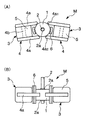
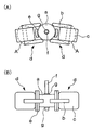
以下、本発明の実施の形態に係るモータについて、図1の平面図及び側面図を参照して具体的に説明する。
図1において、分布型PMモータMは、ロータ1とロータ1を介して対向する一対のステータ3,3とから構成される。ロータ1は、10極の磁極を着磁した永久磁石構造体から構成され、その中心軸線上にボス部2aを有するロータ軸2を備えている。
ステータ3はヨーク4とコイル5とから構成される。ヨーク4は、対向する一対の脚部4a,4aとこれを連結する連結部4bとで構成されるH字形状の軟磁性材料により形成される。コイル5はヨークの連結部4b上に直に導線を巻回して形成されており、巻回コイル5は一対の脚部4a,4a間に位置する。このようなステータ3は、各脚部4a内端部の円弧面に切欠形成された磁極部4a1,4a2がロータ1の外周面に沿って近接して位置するよう、ロータ1の周囲に配置される。
更に、各ステータ3におけるヨーク4の両端の磁極部4a1,4a2間には、円弧状の補助ヨーク6がロータ1の外周面に沿って配置されている。
Hereinafter, a motor according to an embodiment of the present invention will be specifically described with reference to a plan view and a side view of FIG.
In FIG. 1, the distributed PM motor M includes a
The
Further, arc-shaped
一対のステータ3,3は、ロータ軸2に対して、交差角198°のハ字状に配置されている。また、各コイル5は、駆動回路(図示せず)に接続されており、パルス電流により磁極部4a1,4a2を励磁可能としている。従って、各コイル5に任意のパルス電流を通電することにより、ロータ1を所望の方向に所望の量だけ回転させることができる。
The pair of
本実施の形態において、ロータ1は、モータMが適用される機器に応じて適宜のサイズに設定され、2極以上の磁極を着磁したものであれば特に限定されるものではない。例えば、モータMが携帯用電子機器に組み込まれる小型のステッピングモータである場合、ロータ1の直径は2〜4mmの範囲にあることが好ましい。
H字形状のヨーク4は、一対の脚部4a,4aとこれらの端部以外の中間領域を連結する連結部4bとから構成される。一対の脚部4a,4aは完全に平行な関係になくてもよく、また、連結部4bの両端は各脚部4aの内端から外端の長さ方向1/2〜3/4の部分に連結していることが好ましい。図1には、上記長さ方向の略2/3の部分に連結部4bが連結したヨーク4の好適な例を図示している。
同一のサイズのヨークを用いてモータMのトルクを同一とする場合は、スペース効率の観点から、コイル5の外周部が一対の脚部4a,4aの外端部とほぼ等しい位置にあることが好ましい。しかし、コイル5が脚部4a,4a間から多少露出したり、あるいはコイルの外周面が脚部4a,4aの外端部に達していなくてもよい。
In the present embodiment, the
The H-
When the torque of the motor M is made the same using the yoke of the same size, the outer peripheral part of the
一般に、小型のモータの場合、大型のモータと比較してコイルの巻線形状を安定化させることが困難であるが、本発明によれば、前述の理由により、コイルの巻線形状が安定化してコイルの巻崩れが防止される。その結果、コイルの巻線工程が簡素化され、モータへのステータの固定が容易となる。しかも、上述のステータのスペース効率を向上させることも可能である。
このように、本発明の実施の形態においては、モータMは小型のモータとして利用すると好適である。
In general, in the case of a small motor, it is difficult to stabilize the coil winding shape as compared with a large motor. However, according to the present invention, the coil winding shape is stabilized for the reasons described above. Coil collapse is prevented. As a result, the coil winding process is simplified, and the stator can be easily fixed to the motor. In addition, it is possible to improve the space efficiency of the stator described above.
Thus, in the embodiment of the present invention, the motor M is preferably used as a small motor.
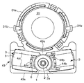
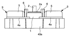
次に、一例として、本発明に係るモータとしてステッピングモータが組み込まれたAF機構を有する光学モジュールについて、図2〜図5を参照して以下に説明する。理解を容易にするために、図4には、光学モジュールにおける駆動部とレンズホルダ下部との配置関係を表す平面図が示されており、図5はその駆動部を示している。
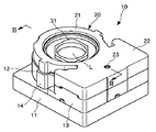
光学モジュール10は、図2及び図3(A)に示すように、基台11と、保護カバー20と、光学系ユニット30と、ステッピングモータを包含する駆動部40とを備えている。なお、光学系ユニット30の下部は基台11により構成される。
Next, as an example, an optical module having an AF mechanism in which a stepping motor is incorporated as a motor according to the present invention will be described below with reference to FIGS. For easy understanding, FIG. 4 shows a plan view showing the positional relationship between the drive unit and the lower part of the lens holder in the optical module, and FIG. 5 shows the drive unit.
As shown in FIGS. 2 and 3A, the
基台11は、底部11aと、光学系ユニット30の構成部材である鏡筒12と、鏡筒12に隣接して駆動部40の下部を形成する壁部13とから構成される。鏡筒12は、一部が仕切壁11bに置き換えられた円筒体で形成される。壁部13は、鏡筒12の仕切壁11bを共有し、上面が開口した矩形状の垂直壁体で形成される。
鏡筒12は略環状の大径部12aと環状の小径部12bとから構成される。小径部12bの底面が臨む基台11の底部11a開口には、所定の配線パターンが形成された基板15が嵌着されている。この基板15上には撮像素子であるCCD(Charge Coupled Device; 図示せず)が固定される。
The
The
保護カバー20は、鏡筒12と壁部13との上面をそれぞれ覆う円筒状の第一カバー部21と無底の略直方体形状をなす第二カバー部22とから構成される。第二カバー部22の上面中央には、前記ロータ軸2の上端部を軸支する軸受孔23が形成されている。
The
光学系ユニット30は、1枚のレンズLを保持する筒状のレンズホルダ31と、円筒カム33と、前記鏡筒12と、環状のコイルバネ34とを備えている。なお、図2及び図3(A)には、フィルタや絞り等を省略して図示している。
円筒カム33は、その回動により、レンズホルダ31を光軸方向LDに進退自在に移動させる。即ち、円筒カム33には、その上面(光の入射側面)にカム面33aが形成され、下部外周面にラック部33bが形成されている。ラック部33bは、基台11に設けられた後述の軸17に固定されるギア42bと噛合する。円筒カム33は、基台11の底部11aとレンズホルダ31の後述するカムフォロア31bとの間に配置される。このような円筒カム33は、レンズLを綴出(AF)させることができる。
The
The
レンズホルダ31下部の外周面には、フランジ部31aが形成されている。フランジ部31aの上部には、半径方向に突出して対向する一対の上記カムフォロア31bが形成されている。レンズホルダ31は、フランジ部31aの下部を鏡筒12の小径部12b外周面と円筒カム33の内周面との間に嵌入させ、かつ、カムフォロア31bを鏡筒12の大径部12aに形成された突出部14の溝内に嵌合させることによって、鏡筒12に摺動自在に案内される。
コイルバネ34は、レンズホルダ31を円筒カム33側に付勢するものであり、上記カムフォロア31bに形成された溝内に載置され、レンズホルダ31の外周部と保護カバー20との間の空間に配置される。このコイルバネ34の付勢力により、カムフォロア31bの下面が円筒カム33のカム面33aに当接する。
A
The
駆動部40は、前記円筒カム33を回動させるものであり、本発明に係るモータと、ロータ軸2に設けられたギア41と、図3(B)に示す2枚のギア42と、図4及び図5に示す電磁アクチュエータ固定部材43とを備えている。
前記ロータ軸2は、上部ボス部2aと、大径の下部ボス部2bと、ギア取付部2cとが一体成形されており、ロータ軸2の両端部がそれぞれ第二カバー部22の前記軸受孔23及び電磁アクチュエータ固定部材43の底板に形成された軸受部(図示せず)に軸支される。また、各ステータ3は、ヨーク両端の磁極部4a1,4a2がロータ1の外周面に近接して位置するように、電磁アクチュエータ固定部材43の底板から突設された位置決め部材に挟持されている。補助ヨーク6も、その背面及び両側面がそれぞれ上記固定部材43に設けられた位置決め部材44a,44bによって支持されている。
The
In the
ギア42は、基台11の底部11aから上方に延びる回転自在の軸17に二段に固定される。一方のギア42aはロータ軸2に設けられたギア41と噛合し、他方のギア42bは円筒カム33の前記ラック部33bに噛合する。
電磁アクチュエータ固定部材43には、レンズホルダ31と反対側に垂直な側壁43aが形成されている。また、レンズホルダ31側のアクチュエータ固定部材43には段差部43bが形成されている。段差部43bは、ステータ3,3の位置決め部であり、レンズホルダ31の位置決めも兼ねている。
また、前記保護カバー20は、適宜の手段より基台11に固定されることによって、光学系ユニット30及び駆動部40を保護する以外に、コイルバネ34の押さえバネとして作用する。
The
The electromagnetic
In addition to protecting the
図4に示すように、レンズLを含む光学ユニット30の外周部に一対のステータ3,3が配置されている。一対のステータ3,3は組み合わされてく字状を構成し、各ステータ3が光学ユニット30の外周に沿う向きに配置されている。この配置構成により、ステータ3,3を光学系ユニット30及び駆動部40の下部空間に効率的に配置することができ、光学モジュール10をよりコンパクト化することが可能となる。
As shown in FIG. 4, a pair of
以上の光学モジュール10において、1枚のレンズLを綴出(AF)させるには、ステータコイル5に流す電流を制御して、ヨーク両端の磁極部4a1,4a2の磁極を変化させてロータ1を回転させる。ロータ1の回転に伴って、ロータ軸2が回転すると共に、ロータ軸2に固定されたギア41と噛合するギア42aが固定された軸17も回転する。軸17の回転に伴って、他方のギア42bが円筒カム33のラック部33bと噛合しているので、円筒カム33も回動する。円筒カム33の回動に伴い、円筒カム33のカム面33a上をカムフォロア31bが摺動することにより、カムフォロア31bの摺動軌跡に対応してレンズホルダ31が光軸方向LDに移動する。これにより、レンズホルダ31に取り付けられたレンズLが綴出(AF)する。即ち、レンズLとCCDとの距離であるバックフォーカスを変化させることができる。
In the
光学モジュール10の駆動部40を組み立てるには、まず、円筒カム33のラック部33bと噛合するように、基台11に設けられた軸17にギア42bを固定する。次に、電磁アクチュエータ固定部材43にステッピングモータを固定して、ロータ軸2に設けられたギア41と基台11の軸17に固定されたギア42aとが噛合するように、アクチュエータ固定部材43を基台11に取り付けることにより、駆動部40が組み立てられる。
To assemble the
本発明に係るモータは、カメラを搭載した携帯電話や、ノート型パソコン、複写機、ファクシミリ、携帯型テレビ電話等のOA機器などに適用可能である。
以上のような本発明に係るモータは、好適には、コイルの巻崩れの懸念がある小型のモータとして利用される。
The motor according to the present invention can be applied to mobile phones equipped with cameras, office computers such as notebook computers, copiers, facsimiles, and portable videophones.
The motor according to the present invention as described above is preferably used as a small motor having a risk of coil collapse.
1 ロータ
3 ステータ
4 ヨーク
4a 脚部
4b 連結部
4a1,4a2 磁極部
5 コイル
M モータ
DESCRIPTION OF
Claims (5)
前記一対のステータは組み合わされてく字状を構成し、かつ、各ステータは前記光学ユニットの外周に沿う向きに配置されている、ことを特徴とする請求項4に記載の光学モジュール。 A pair of the stators are disposed on the outer periphery of the optical unit including the lens system,
The optical module according to claim 4, wherein the pair of stators are combined to form a square shape, and each stator is disposed in a direction along an outer periphery of the optical unit.
Priority Applications (1)
| Application Number | Priority Date | Filing Date | Title |
|---|---|---|---|
| JP2004108394A JP2005295710A (en) | 2004-03-31 | 2004-03-31 | motor |
Applications Claiming Priority (1)
| Application Number | Priority Date | Filing Date | Title |
|---|---|---|---|
| JP2004108394A JP2005295710A (en) | 2004-03-31 | 2004-03-31 | motor |
Publications (1)
| Publication Number | Publication Date |
|---|---|
| JP2005295710A true JP2005295710A (en) | 2005-10-20 |
Family
ID=35328032
Family Applications (1)
| Application Number | Title | Priority Date | Filing Date |
|---|---|---|---|
| JP2004108394A Pending JP2005295710A (en) | 2004-03-31 | 2004-03-31 | motor |
Country Status (1)
| Country | Link |
|---|---|
| JP (1) | JP2005295710A (en) |
Cited By (1)
| Publication number | Priority date | Publication date | Assignee | Title |
|---|---|---|---|---|
| JP2008011673A (en) * | 2006-06-30 | 2008-01-17 | Yazaki Corp | Stepper motor and stepper motor device |
-
2004
- 2004-03-31 JP JP2004108394A patent/JP2005295710A/en active Pending
Cited By (1)
| Publication number | Priority date | Publication date | Assignee | Title |
|---|---|---|---|---|
| JP2008011673A (en) * | 2006-06-30 | 2008-01-17 | Yazaki Corp | Stepper motor and stepper motor device |
Similar Documents
| Publication | Publication Date | Title |
|---|---|---|
| JP7292470B2 (en) | lens drive motor | |
| JP5963641B2 (en) | Lens drive device | |
| JP5295830B2 (en) | Lens drive device | |
| USRE44371E1 (en) | Camera module | |
| JP4442639B2 (en) | The camera module | |
| JP5048422B2 (en) | Automatic focus adjustment structure for camera | |
| JP4732853B2 (en) | LENS DRIVE DEVICE AND ELECTRONIC DEVICE | |
| JP2008197313A (en) | Lens drive device | |
| JP2008052196A (en) | Lens drive device | |
| JP2008268475A (en) | Voice coil type lens driving device | |
| JP2012058376A (en) | Lens driving device | |
| JP5265422B2 (en) | Lens drive device | |
| JP2008310288A (en) | Camera motor | |
| JP5046304B2 (en) | Light control device | |
| JP2009251474A (en) | Lens unit and imaging apparatus | |
| KR102599137B1 (en) | Voice coil motor | |
| JP2009198948A (en) | Lens driving device and camera device | |
| JP2006047356A (en) | Lens drive device | |
| JP6181990B2 (en) | Optical device for photography | |
| JP2009150922A (en) | Actuators, imaging devices and portable electronic devices | |
| JP2005295710A (en) | motor | |
| JP2011221212A (en) | Lens driving device | |
| KR100817033B1 (en) | Auto focusing device of small lens module | |
| KR20130051616A (en) | Lens actuator | |
| JP2022018272A (en) | Light quantity adjustment device and portable terminal |
Legal Events
| Date | Code | Title | Description |
|---|---|---|---|
| A621 | Written request for application examination |
Free format text: JAPANESE INTERMEDIATE CODE: A621 Effective date: 20061006 |
|
| A977 | Report on retrieval |
Free format text: JAPANESE INTERMEDIATE CODE: A971007 Effective date: 20090416 |
|
| A131 | Notification of reasons for refusal |
Free format text: JAPANESE INTERMEDIATE CODE: A131 Effective date: 20090616 |
|
| A02 | Decision of refusal |
Free format text: JAPANESE INTERMEDIATE CODE: A02 Effective date: 20091020 |