JP2005295765A - Armature for dynamo-electric machine - Google Patents
Armature for dynamo-electric machine Download PDFInfo
- Publication number
- JP2005295765A JP2005295765A JP2004111102A JP2004111102A JP2005295765A JP 2005295765 A JP2005295765 A JP 2005295765A JP 2004111102 A JP2004111102 A JP 2004111102A JP 2004111102 A JP2004111102 A JP 2004111102A JP 2005295765 A JP2005295765 A JP 2005295765A
- Authority
- JP
- Japan
- Prior art keywords
- teeth
- circumferential direction
- armature
- core material
- tooth
- Prior art date
- Legal status (The legal status is an assumption and is not a legal conclusion. Google has not performed a legal analysis and makes no representation as to the accuracy of the status listed.)
- Pending
Links
- 210000000078 claw Anatomy 0.000 claims abstract description 20
- 239000011162 core material Substances 0.000 claims description 68
- 238000004804 winding Methods 0.000 claims description 4
- 238000010030 laminating Methods 0.000 claims description 2
- 230000004907 flux Effects 0.000 abstract description 26
- 230000007423 decrease Effects 0.000 description 11
- 238000010586 diagram Methods 0.000 description 4
- 230000009467 reduction Effects 0.000 description 4
- 230000002093 peripheral effect Effects 0.000 description 3
- 230000000694 effects Effects 0.000 description 2
- 230000005611 electricity Effects 0.000 description 2
- 230000006872 improvement Effects 0.000 description 2
- 230000008901 benefit Effects 0.000 description 1
- 230000003247 decreasing effect Effects 0.000 description 1
- 230000007547 defect Effects 0.000 description 1
- 230000006866 deterioration Effects 0.000 description 1
- 230000001788 irregular Effects 0.000 description 1
- 238000005259 measurement Methods 0.000 description 1
- 238000000034 method Methods 0.000 description 1
- 230000008569 process Effects 0.000 description 1
Images
Landscapes
- Iron Core Of Rotating Electric Machines (AREA)
Abstract
Description
本発明は、車両に搭載される電装品等を構成する回転電機の電機子の技術分野に属するものである。 The present invention belongs to the technical field of an armature of a rotating electrical machine that constitutes electrical components and the like mounted on a vehicle.
一般に、この種回転電機において、これが例えば電動モータであった場合、内周面に複数対の永久磁石により複数の磁極が形成されたヨーク(界磁)に、アーマチュア(電機子)を回転自在に軸承して構成されたものがあり、このようなものにおいて、アーマチュアは、アーマチュア軸に複数枚のコア材を積層状に外嵌してアーマチュアコアを形成し、該アーマチュアコアの外周にコイルが巻装されたものに構成されている。前記コア材は、リング状のボス部の外径に、基部と、該基部先端から周回り方向に延出する爪部とで略T字状に形成されるティースが複数配されたものとなっており、これらが積層されたアーマチュアコアの外周に、隣接ティース間であるスロット(コイル溝)が軸方向を向いて形成され、これらコイル溝にコイルが巻装されている。
ところで、電動モータにおいては、駆動時のコギングトルクの低下が課題であるが、該コギングトルクの主な発生原因の一つとして、ヨーク側に配される永久磁石の磁極端でのティースの磁束密度の変化(磁気抵抗変化)があり、このため、コア材を偶数のティースが形成されたものにした場合、径方向に対向するティースに発生するトルクが同位相となるためコギングトルクが大きくなってしまうことが知られており、奇数のティースが形成されたコア材の方が好適であることが知られている。しかるに、奇数のティースが形成されたコア材で構成されるアーマチュアコアは量産性が悪く、どうしてもコスト高となってしまううえ、コイルの巻装工程においても複雑になるという問題がある。これに対し、コア材を積層させたときスロット対応部位に形成されるコイル溝をアーマチュア軸とは変位する状態、即ちスキューさせる状態とすることが提唱され、このようにすることで永久磁石端部とティースとのあいだで生じる磁束密度変化を緩和させるようにしたものが提唱されている。しかるに、このものでは、コギング低下の効果を充分に得ることはできず、依然問題が残されるうえ、このようにスキューさせた場合では、有効磁束の低下に伴い特性劣化と巻線性が悪くなるという不具合が生じるという問題がある。
Generally, in this type of rotating electric machine, when this is an electric motor, for example, an armature (armature) can be freely rotated on a yoke (field) in which a plurality of magnetic poles are formed by a plurality of pairs of permanent magnets on an inner peripheral surface. Some armatures are configured by bearings. In such an armature, an armature is formed by stacking a plurality of core materials on an armature shaft in a laminated manner to form an armature core, and a coil is wound around the outer periphery of the armature core. It is configured to be worn. In the core material, a plurality of teeth formed in a substantially T shape are arranged on the outer diameter of the ring-shaped boss portion, with a base portion and a claw portion extending in a circumferential direction from the tip of the base portion. Slots (coil grooves) between adjacent teeth are formed on the outer periphery of the armature core on which these are laminated so as to face the axial direction, and coils are wound around these coil grooves.
By the way, in an electric motor, a reduction in cogging torque at the time of driving is a problem. One of the main causes of the cogging torque is a magnetic flux density of teeth at the magnetic pole end of a permanent magnet arranged on the yoke side. Therefore, when the core material is formed with even-numbered teeth, the torque generated in the teeth facing in the radial direction becomes the same phase, so the cogging torque increases. It is known that a core material in which an odd number of teeth is formed is more suitable. However, an armature core composed of a core material on which odd-numbered teeth are formed has a problem in that it is not mass-productive and is inevitably costly and complicated in the coil winding process. On the other hand, it is proposed that when the core material is laminated, the coil groove formed at the slot corresponding portion is displaced from the armature shaft, that is, in a skewed state. Has been proposed to mitigate magnetic flux density changes that occur between teeth and teeth. However, in this case, the effect of lowering the cogging cannot be obtained sufficiently, and problems still remain, and when skewed in this way, the characteristic deterioration and the winding property become worse as the effective magnetic flux decreases. There is a problem that a defect occurs.
この改善策として、永久磁石の周回り方向両端部を薄板状(偏芯状)とし、これによって、アーマチュアコアと永久磁石端部部位における対向間隔を広くしてコギングトルクの低減を計るようにすることが提唱されている。
しかるに、前記従来のものでは、コギングトルクの低減は果せるものの、永久磁石を薄板状にする分、有効磁束量の低下が生じてしまうという問題があり、高性能の電動モータが要望されるなか、有効磁束量を低下させることなくコギングトルクの低減を図ることが強く要求され、ここに本発明が解決しようとする課題がある。 However, in the above-mentioned conventional one, although the cogging torque can be reduced, there is a problem that the amount of effective magnetic flux decreases because the permanent magnet is made into a thin plate shape, and a high-performance electric motor is desired. There is a strong demand to reduce cogging torque without reducing the amount of effective magnetic flux, and there is a problem to be solved by the present invention.
本発明は、上記の如き実情に鑑みこれらの課題を解決することを目的として創作されたものであって、請求項1の発明は、複数のコア材を積層しコイルを巻装してなる電機子と、少なくとも一対の磁極を形成する界磁とを備えた回転電機において、前記コア材は、リング状のボス部の周回りに、該ボス部から径方向に突出する基部の先端に周回り方向に延出する爪部が形成された略T字状のティースが偶数個配されるものとし、前記ティースを、爪部外径縁の周回り方向一方に切り欠き溝が形成された第一ティースと、周回り方向他方に切り欠き溝が形成された第二ティースとで構成し、予め設定される所定数の第一ティースが隣接する第一ティース群と、前記所定数の第二ティースが隣接する第二ティース群とを周回り方向交互に配し、各磁極の周回り方向一方の磁極端に対向する第一ティースの数と第二ティースの数とが同じになるように構成されているものである。
そして、このようにすることにより、有効磁束量を低下させることなくコギングトルクの低減を図ることができる。
請求項2の発明は、請求項1において、回転電機を二極としたとき、コア材は、nを2以上の自然数、mを奇数としたとき、周回り方向に(2×n×m)個のティースが形成され、各第一、第二ティース群はそれぞれn個の第一、第二ティースで構成されているものであり、このようにすることにより、二極の回転電気において、有効磁束量を低下させることなくコギングトルクの低減を図ることができる。
請求項3の発明は、請求項1において、回転電機を四極以上であって2p極と示すとき、コア材のティースは、nを2以上の自然数、mを奇数としたとき、周回り方向に(p×n×m)または(2p×n×m)個のティースが形成され、各第一、第二ティース群はそれぞれn個の第一、第二ティースで構成されているものであり、このようにすることにより、四極以上の回転電機において、有効磁束量を低下させることなくコギングトルクの低減を図ることができる。
The present invention has been created in view of the above circumstances and has been created for the purpose of solving these problems. The invention of
And by doing in this way, reduction of cogging torque can be aimed at, without reducing the amount of effective magnetic fluxes.
According to a second aspect of the present invention, in the first aspect, when the rotating electric machine has two poles, the core material has a circumferential direction (2 × n × m) when n is a natural number of 2 or more and m is an odd number. Each tooth is formed, and each first and second tooth group is composed of n first and second teeth. By doing so, it is effective in rotating electricity with two poles. The cogging torque can be reduced without reducing the amount of magnetic flux.
According to a third aspect of the present invention, in the first aspect, when the rotating electrical machine is four poles or more and 2p poles, the teeth of the core material are in the circumferential direction when n is a natural number of two or more and m is an odd number. (P × n × m) or (2p × n × m) teeth are formed, and each first and second tooth group is composed of n first and second teeth, respectively. By doing so, in a rotating electric machine having four or more poles, it is possible to reduce the cogging torque without reducing the effective magnetic flux amount.
請求項1の発明とすることにより、有効磁束量を低下させることなくコギングトルクの低減を図ることができる。
請求項2の発明とすることにより、二極の回転電気において、有効磁束量を低下させることなくコギングトルクの低減を図ることができる。
請求項3の発明とすることにより、四極以上の回転電機において、有効磁束量を低下させることなくコギングトルクの低減を図ることができる。
By setting it as invention of
According to the second aspect of the present invention, the cogging torque can be reduced without reducing the effective magnetic flux amount in the rotating electricity with two poles.
According to the invention of
つぎに、本発明の実施の形態について、図1〜4の図面に基づいて説明する。
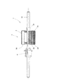
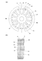
図面において、1は回転電機のアーマチュア(本発明の電機子に相当する)であって、該アーマチュア1は、回転中心となるアーマチュア軸1aが電動モータの有底筒状のヨーク(図示せず)に回転自在に軸承されること等の基本的な構成は従来通りとなっている。尚、本実施の形態では、ヨークの内周面に、均一な板厚を有した円弧形状の永久磁石Mが固着されて界磁を構成しているが、本実施の形態では、ヨークに一対の永久磁石Mを固着することにより、二極の電動モータを構成するように設定されている。
Next, an embodiment of the present invention will be described based on the drawings of FIGS.
In the drawings,
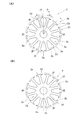
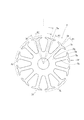
2はアーマチュア1を構成する薄板状のコア材であって、該コア材2は、リング状のボス部2aの外周に、外径側に放射状に突出する基部2bの先端に周回り方向に長く延出する爪部2cが形成された略T字状のティースが周回り方向に複数形成されたものに構成されている。そして、複数枚のコア材2のボス部2aを、アーマチュア軸1aに回り止め状に外嵌せしめることでアーマチュアコア3を構成するように設定されている。ここで、本実施の形態のコア材2は、図2に示すように、周回り方向に偶数である12個のティースが形成されたものになっており、これによって、コア材2を積層して構成されるアーマチュアコア3の外周には、隣接するティース間に12個のスロット(コイル溝)3aが軸方向に長く形成され、これらスロット3aにコイル(図示せず)が巻装されるように設定されている。前記各コイルの両端部は、アーマチュア軸1aに一体的に外嵌されたコンミテータ4に接続されており、該コンミテータ4に外部電源が供給されるように設定されている。
2 is a thin plate-shaped core material constituting the
本実施の形態は、前述したように、二極の電動モータに構成されており、このため、コア材2に形成されるティースの数は、nを2以上の自然数、mを奇数としたとき、(2×n×m)の式を満足する個数となるように設定されている。即ち、本実施の形態のティースの個数は、nを2、mを3とした場合のティース数に相当する12個のティースが形成されており、隣接する爪部2cの中心部同志間の角度θ1は(360/12=30)度となるように設定されている。
As described above, the present embodiment is configured as a two-pole electric motor. For this reason, the number of teeth formed on the
さらに、コア材2外周に形成される各ティースは、各ティースのうち、半数(六個)のものは、周回り方向中央部を基準として、爪部2c外径縁部の周回り方向一方に位置して内径側に切り欠かれる切り欠き溝2dが形成された第一ティース2eに構成されている。ここで、第一ティース2eは、爪部2cの中心部から切り欠き溝2dの溝中心とのあいだが予め設定される角度θ2を存して形成されている。さらに、残りの半数(6個)のものは、周回り方向中央部を基準として、爪部2cの外径縁部の周回り方向他方に位置して内径側に切り欠かれる切り欠き溝2dが形成された第二ティース2fに構成されている。前記第二ティース2fは、爪部2cの中心部から切り欠き溝2dの溝中心とのあいだが前記第一ティース2eと同様に角度θ2となるように形成されている。そして、これら第一、第二ティース2e、2fとは、図2に示すように、ボス部2aの外周に周回り方向n個づつ、本実施の形態では二個づつ並んで第一ティース群2Eと第二ティース群2Fを構成しており、これら第一、第二ティース群2E、2Fとは、それぞれ三群づつのものが交互に配設されてコア材2を構成するように設定されている。
Furthermore, as for each tooth formed on the outer periphery of the
そして、このように構成されたコア材2において、各極を構成する永久磁石MN、MSの周回り方向一端部にそれぞれ対向するティースは、図3(A)に示すように、互いに径方向に対向するティースとなる。本実施の形態のコア材2は、前述したように、二個づつの第一、第二ティース2e、2fで構成された三個の第一、第二ティース群2E、2Fが周回り方向に交互に並んでいるので、各永久磁石MN、MSの一端部に対向するティース(コア材2において径方向に対向するティース)は、それぞれ第一、第二ティース2e、2fとなるように設定されている。
Then, in the
そして、各コア材2は、アーマチュア軸1aの外周に外嵌して積層されるにあたり、軸方向に第一ティース2e同志、第二ティース2f同志がそれぞれ並ぶような外嵌状態となっている。これによって、ヨークにアーマチュア1を軸承させたとき、アーマチュア12は、S極の永久磁石MSの周回り方向一端部に対して第一ティース2eが対向したときは、N極の永久磁石MNの周回り方向一端部に対して第二ティース2fが対向し、これとは逆にS極の永久磁石MSの周回り方向一端部に対して第二ティース2fが対向したときは、N極の永久磁石MNの周回り方向一端部に対して第一ティース2eが対向するように設定され、永久磁石MN、MSの周回り方向一方の端部(磁極端)に対向する第一ティース2fと第二ティース2gとの数が同じ数(1個づつ)となるように構成されている。
Each
叙述の如く構成された本発明の実施の形態において、アーマチュアコア3の各スロット3aに巻装されるコイル4に通電することで、アーマチュア3の回転がなされるが、この場合に、アーマチュアコア3を構成する各コア材2に形成されるティースは、nを2以上の自然数、mを奇数としたとき、(2×n×m)で示される個数のものが形成されているとともに、爪部2cの周回り方向中央部を基準として、周回り方向一方に切り欠き溝2dが形成された第一ティース2eと、周回り方向他方に切り欠き溝2dが形成された第二ティース2fとが半数づつ形成され、第一、第二ティース2e、2fとは、それぞれn(2)個づつで第一または第二ティース群2E、2Fを構成しており、かつ、これら第一、第二ティース群2E、2Fが周回り方向交互に配設されている。このため、永久磁石MN、MSの周回り方向一方の端部である磁極端に対向するティースは、常に第一ティース2eと第二ティース2fとの二種類となり、同じ形状のティースが対向することがない。この結果、各磁極端部位に対向することによる第一、第二ティース2e、2fの磁束密度の変化がそれぞれ異なったものとなり、コギングトルクやトルクむらの発生を低減させ、バランスのよい回転を得ることができる。しかも、このものでは、永久磁石MN、MSの形状を磁極端側部位を薄板状にすることなく、均一な板厚のままにしながらコギングトルクを低減することができるので、磁極端部位で有効磁束量が低下してしまうことがなく、もって、より高性能、高品質な電動モータを提供することができる。
In the embodiment of the present invention configured as described above, the
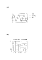
つぎに、本実施の形態のアーマチュアが用いられている電動モータ(本発明品)と、ティース(アーマチュア)は従来型であるが永久磁石の磁極端部位を薄板状(偏芯状)にした電動モータ(従来改良品)と、ティース(アーマチュア)、永久磁石とも従来型の電動モータ(従来品)を用いてコギングトルクを測定した結果を図4(A)に示す。
図4(A)によると、従来品に比し、従来改良品ではコギングトルクの波形が小さくなっており、コギングトルクの低下が図れていることが実証されるが、さらに、本発明品では、従来改良品よりもさらなるコギングトルクの低下が図れていることが解る。
また、前記と同様の本発明品、従来改良品、従来品の各電動モータにおけるコギングトルクと、有効磁束量とについて、従来品を1としたときの割合を示したグラフ図を図4(B)に示すが、該グラフ図からも明らかなように、従来改良品では、コギングトルクの低減はなされるものの有効磁束量の低下の割合が大きく、本発明品を用いた電動モータでは、有効磁束量の低下を押さえつつ、コギングトルクの低下が図られていることがわかる。
Next, the electric motor (product of the present invention) in which the armature of the present embodiment is used and the teeth (armature) are conventional, but the electric pole end portion of the permanent magnet is made thin (eccentric). FIG. 4A shows the results of measuring cogging torque using a conventional electric motor (conventional product) for both the motor (conventional improvement product), teeth (armature), and permanent magnet.
According to FIG. 4 (A), compared with the conventional product, it has been demonstrated that the waveform of the cogging torque is smaller in the conventional improved product and the cogging torque can be reduced. It can be seen that the cogging torque can be further reduced as compared with the conventional improved product.
Further, FIG. 4B is a graph showing the ratio of the conventional product as 1 with respect to the cogging torque and the effective magnetic flux amount in the respective electric motors of the present invention, the conventional improved product, and the conventional product similar to the above. As is clear from the graph, the conventional improved product has a reduced rate of effective magnetic flux although the cogging torque is reduced. In the electric motor using the product of the present invention, the effective magnetic flux is reduced. It can be seen that the cogging torque is reduced while suppressing the decrease.
尚、本発明は前記実施の形態に限定されないことは勿論であって、つぎに説明する第二の実施の形態のような構成とすることができる。
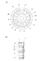
第二の実施の形態のアーマチュア6は、前記第一の実施の形態のコア材2を用いて構成されている。前記コア材2は、ティース基部2bが放射状に形成されており、隣接するコア材2同志を、各ティース群2E、2Fにおけるティース数分の周回り角度(この場合では60度)を回転させて積層することにより、異形の爪部2c同志が重なるように構成されている。そして、第二の実施の形態のものは、前述したように異形の爪部2c同志が軸方向に隣接するようコア材2をそれぞれ60度づつ回転させた状態で積層されたアーマチュア6になっていて、図5に示すように、切り欠き溝2dがそれぞれ隣接コア材2により覆蓋されるように構成されている。そうして、このものでも、各コア材2において、磁極端に対向するティースは、常に第一ティース2eと第二ティース2fとの二種類となることとなり、このようなアーマチュア6を、同一板厚の永久磁石を備えたヨークに軸承させることにより、有効磁束量の低下を回避し、かつ、前記第一の実施の形態のものに比してコギングトルクの低減は劣るものの略同様の効果を得ることができることが確認された。
Of course, the present invention is not limited to the above-described embodiment, and may be configured as in the second embodiment described below.
The
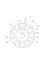
つぎに、図6に示す第三の実施の形態について説明する。第三の実施の形態のコア材7は、前記第一、二の実施の形態のコア材2と略同様に、ボス部7aから複数の基部7bが放射状に形成され、該基部7bの先端に周回り方向に長い爪部7cが形成されてティースを構成し、前記爪部7c外径縁部の周回り方向一方に切り欠き溝7dが形成された第一ティース7eと、周回り方向他方に切り欠き溝7dが形成された第二ティース7fとにより構成されている。さらに、本実施の形態の各ティース7e、7fは、爪部7cの外径縁部の周回り方向中央部に位置して内径側に凹溝部7gが切り欠き形成されたものに構成されている。そして、前記コア材7を用いて形成されたアーマチュアを、同一板厚の永久磁石を備えたヨークに軸承させることにより、磁極端に対向するティースは常に第一ティース7eと第二ティース7fとの二種類となり、有効磁束量の低下を回避し、かつ、前記第一の実施の形態と略同様のコギングトルクの低減を果せることが確認された。
Next, a third embodiment shown in FIG. 6 will be described. In the
図7に示す第四の実施の形態は、コア材8のボス部8aから突出する基部7bの突出方向が放射状ではなく、これによって、アーマチュア軸に外嵌してアーマチュアコアを構成したとき、隣接するティース同志のあいだに形成されるスロット形状がそれぞれ異形となるように構成されている。前記コア材8の爪部8cの外径縁部には、第一の実施の形態同様に周回り方向一方または他方に切り欠き溝8dが形成されて、第一ティース8eと第二ティース8fとを構成している。そして、前記コア材8を用いて構成したアーマチュアを、同一板厚の永久磁石を備えたヨークに軸承させることにより、磁極端に対向するティースが常に第一ティース8eと第二ティース78との二種類となり、有効磁束量の低下を回避しつつ、コギングトルクの低減を果せることが確認された。さらに、このものでは、異形スロットに構成されているため、コイルの巻装状態を良好かつコンパクト化できるという利点を付加することができる。
In the fourth embodiment shown in FIG. 7, the protruding direction of the
さらに、二極の電動モータに用いられるアーマチュアのコア材としては、(2×n×m)で示されるティース数で、かつ、第一、第二ティースがn個づつの群になったコア材を用いることにより、一対の永久磁石の磁極端に対向するティースを、それぞれ第一、第二ティースとすることができ、有効磁束量の低下を回避しつつ、コギングトルクの低下を防止することができる。
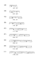
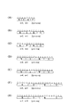
因みに、図8(A)〜(I)に、二極電動モータ用のコア材の他例を、永久磁石とティース形状との関係を説明するためにそれぞれを展開したパターン図として示す。図中、○印は第一ティースを、△印は第二ティースを示すものとする。そして、これらのコア材を用いたアーマチュアは、何れのものでも、板厚が均等な一対の永久磁石を設けたヨークに軸承することで、有効磁束量の低下を回避しつつ、コギングトルクの低減を図れることが確認された。
Furthermore, as the core material of the armature used for the two-pole electric motor, the number of teeth indicated by (2 × n × m) and the core material in which the first and second teeth are in groups of n. The teeth facing the magnetic pole ends of the pair of permanent magnets can be used as the first and second teeth, respectively, and the decrease in the effective magnetic flux amount can be avoided and the decrease in the cogging torque can be prevented. it can.
Incidentally, in FIGS. 8A to 8I, other examples of the core material for the two-pole electric motor are shown as developed pattern diagrams in order to explain the relationship between the permanent magnet and the tooth shape. In the figure, a circle indicates the first tooth, and a triangle indicates the second tooth. And any armature using these core materials can reduce the cogging torque while avoiding a decrease in the effective magnetic flux amount by bearing on a yoke provided with a pair of permanent magnets with equal plate thickness. It was confirmed that
また、極数を2pで示したとき、2p極の電動モータに用いられるアーマチュアのコア材としては、(2p×n×m)または(p×n×m)で示されるティース数で、かつ、第一、第二ティースがn個づつの群になったコア材を用いることにより、p対の永久磁石の磁極端に対向するティースを、それぞれ同数(p個づつ)の第一、第二ティースとすることができ、有効磁束量の低下を回避しつつ、コギングトルクの低下を防止することができる。
因みに、図9(A)〜(G)に、四極電動モータ用のコア材の他例を、永久磁石とティース形状との関係を説明するためにそれぞれを展開したパターン図として示す。図中、○印は第一ティースを、△印は第二ティースを示すものとする。そして、これらのコア材を用いたアーマチュアは、何れのものでも、板厚が均等な一対の永久磁石を設けたヨークに軸承することで、有効磁束量の低下を回避しつつ、コギングトルクの低減を図れることが確認された。
Further, when the number of poles is represented by 2p, the core material of the armature used for the 2p-pole electric motor is the number of teeth represented by (2p × n × m) or (p × n × m), and By using the core material in which the first and second teeth are grouped in groups of n, the same number of teeth (p units) of the first and second teeth facing the magnetic pole ends of the p pairs of permanent magnets. Thus, it is possible to prevent the cogging torque from decreasing while avoiding the decrease in the effective magnetic flux amount.
Incidentally, FIGS. 9A to 9G show other examples of the core material for the four-pole electric motor as a developed pattern diagram for explaining the relationship between the permanent magnet and the tooth shape. In the figure, a circle indicates the first tooth, and a triangle indicates the second tooth. And any armature using these core materials can reduce the cogging torque while avoiding a decrease in the effective magnetic flux amount by bearing on a yoke provided with a pair of permanent magnets with equal plate thickness. It was confirmed that
さらに、前記各実施の形態の電機子は、回転電機の界磁に対して内径側に位置する構成のものであるが、例えばブラシレスモータのような回転電機における電機子のように、界磁の外径側に設けられる電機子に本発明を実施することも可能である。この場合、各コア材は、前記条件に対応する個数のティースとするとともに、ボス部の内径側に向けて形成されるティースに、外径側に向く切り欠き溝を周回り方向一方または他方に形成して第一ティースと第二ティースとし、これらを前記条件に基づいて第一、第二ティース群として周回り方向交互に配することにより、各磁極端に対向するティースを、それぞれ同数の第一、第二ティースとすることができ、有効磁束量の低下を回避しつつ、コギングトルクの低減を図ることができる。 Furthermore, the armature of each of the embodiments described above is configured to be positioned on the inner diameter side with respect to the field of the rotating electrical machine. For example, the armature in a rotating electrical machine such as a brushless motor It is also possible to implement the present invention on the armature provided on the outer diameter side. In this case, each core material has a number of teeth corresponding to the above conditions, and a tooth formed toward the inner diameter side of the boss portion is provided with a notch groove directed toward the outer diameter side in one or the other circumferential direction. The first teeth and the second teeth are formed, and these are alternately arranged in the circumferential direction as the first and second teeth groups based on the above-described conditions. The first and second teeth can be used, and the cogging torque can be reduced while avoiding the decrease in the effective magnetic flux amount.
1 アーマチュア
1a アーマチュア軸
2 コア材
2c 爪部
2d 切り欠き溝
2e 第一ティース
2f 第二ティース
2E 第一ティース群
3 アーマチュアコア
3a スロット
4 コンミテータ
DESCRIPTION OF
Claims (3)
Priority Applications (1)
| Application Number | Priority Date | Filing Date | Title |
|---|---|---|---|
| JP2004111102A JP2005295765A (en) | 2004-04-05 | 2004-04-05 | Armature for dynamo-electric machine |
Applications Claiming Priority (1)
| Application Number | Priority Date | Filing Date | Title |
|---|---|---|---|
| JP2004111102A JP2005295765A (en) | 2004-04-05 | 2004-04-05 | Armature for dynamo-electric machine |
Publications (1)
| Publication Number | Publication Date |
|---|---|
| JP2005295765A true JP2005295765A (en) | 2005-10-20 |
Family
ID=35328078
Family Applications (1)
| Application Number | Title | Priority Date | Filing Date |
|---|---|---|---|
| JP2004111102A Pending JP2005295765A (en) | 2004-04-05 | 2004-04-05 | Armature for dynamo-electric machine |
Country Status (1)
| Country | Link |
|---|---|
| JP (1) | JP2005295765A (en) |
Cited By (4)
| Publication number | Priority date | Publication date | Assignee | Title |
|---|---|---|---|---|
| JP2007267439A (en) * | 2006-03-27 | 2007-10-11 | Mitsuba Corp | Armature core in rotating-electric machine |
| JP2008048517A (en) * | 2006-08-14 | 2008-02-28 | Mitsuba Corp | Armature of rotating electric machine |
| CN107104569A (en) * | 2017-07-04 | 2017-08-29 | 杭州同孚环保科技有限公司 | A kind of motor of use coil permanent magnet combination stator |
| CN114930685A (en) * | 2020-02-07 | 2022-08-19 | 美蓓亚三美株式会社 | Motor |
-
2004
- 2004-04-05 JP JP2004111102A patent/JP2005295765A/en active Pending
Cited By (5)
| Publication number | Priority date | Publication date | Assignee | Title |
|---|---|---|---|---|
| JP2007267439A (en) * | 2006-03-27 | 2007-10-11 | Mitsuba Corp | Armature core in rotating-electric machine |
| JP2008048517A (en) * | 2006-08-14 | 2008-02-28 | Mitsuba Corp | Armature of rotating electric machine |
| CN107104569A (en) * | 2017-07-04 | 2017-08-29 | 杭州同孚环保科技有限公司 | A kind of motor of use coil permanent magnet combination stator |
| CN107104569B (en) * | 2017-07-04 | 2023-04-25 | 杭州同孚环保科技有限公司 | Motor adopting coil permanent magnet combined stator |
| CN114930685A (en) * | 2020-02-07 | 2022-08-19 | 美蓓亚三美株式会社 | Motor |
Similar Documents
| Publication | Publication Date | Title |
|---|---|---|
| EP0823771B1 (en) | Motor | |
| JP5806073B2 (en) | Brushless motor | |
| JP2652080B2 (en) | Hybrid type stepping motor | |
| US20150042194A1 (en) | Single-phase brushless motor | |
| US7245054B1 (en) | Permanent magnet electric machine having reduced cogging torque | |
| JP5589418B2 (en) | Method for manufacturing permanent magnet rotating machine | |
| US20070057589A1 (en) | Interior permanent magnet rotor and interior permanent magnet motor | |
| WO2018037529A1 (en) | Rotary electric machine | |
| JP2013059178A (en) | Magnetic gear | |
| JP2018074663A (en) | Rotary electric machine | |
| US6958556B2 (en) | Structure of rotors in stepping motors | |
| JP2000166135A (en) | Brushless motor | |
| JP4685516B2 (en) | Rotating electric machine armature | |
| JP2010283963A (en) | Rotating armature, rotary electrical machine, and manufacturing method for rotating armatures | |
| JP2003047184A (en) | Armature structure for electric motor | |
| JP2006254622A (en) | Permanent magnet type motor | |
| KR20080090039A (en) | Motor and its manufacturing method | |
| JP4685391B2 (en) | Rotating electrical machine armature and manufacturing method thereof | |
| JP2006020459A (en) | Stator core and dynamo-electric machine equipped with the same | |
| JP2006149167A (en) | Embedded magnet type motor | |
| JP2004260918A (en) | Motor rotor | |
| JP6259805B2 (en) | Rotor and motor | |
| JP2003324872A (en) | Armature of rotating electric machine | |
| US20240186843A1 (en) | Motor | |
| JP2020195257A (en) | Electric motor |