JP2005295766A - Rotor structure of axial gap motor - Google Patents
Rotor structure of axial gap motor Download PDFInfo
- Publication number
- JP2005295766A JP2005295766A JP2004111242A JP2004111242A JP2005295766A JP 2005295766 A JP2005295766 A JP 2005295766A JP 2004111242 A JP2004111242 A JP 2004111242A JP 2004111242 A JP2004111242 A JP 2004111242A JP 2005295766 A JP2005295766 A JP 2005295766A
- Authority
- JP
- Japan
- Prior art keywords
- rotor
- holding member
- rib
- oil passage
- rotating shaft
- Prior art date
- Legal status (The legal status is an assumption and is not a legal conclusion. Google has not performed a legal analysis and makes no representation as to the accuracy of the status listed.)
- Granted
Links
Images
Classifications
-
- H—ELECTRICITY
- H02—GENERATION; CONVERSION OR DISTRIBUTION OF ELECTRIC POWER
- H02K—DYNAMO-ELECTRIC MACHINES
- H02K1/00—Details of the magnetic circuit
- H02K1/06—Details of the magnetic circuit characterised by the shape, form or construction
- H02K1/22—Rotating parts of the magnetic circuit
- H02K1/27—Rotor cores with permanent magnets
- H02K1/2793—Rotors axially facing stators
- H02K1/2795—Rotors axially facing stators the rotor consisting of two or more circumferentially positioned magnets
-
- H—ELECTRICITY
- H02—GENERATION; CONVERSION OR DISTRIBUTION OF ELECTRIC POWER
- H02K—DYNAMO-ELECTRIC MACHINES
- H02K9/00—Arrangements for cooling or ventilating
- H02K9/19—Arrangements for cooling or ventilating for machines with closed casing and closed-circuit cooling using a liquid cooling medium, e.g. oil
- H02K9/197—Arrangements for cooling or ventilating for machines with closed casing and closed-circuit cooling using a liquid cooling medium, e.g. oil in which the rotor or stator space is fluid-tight, e.g. to provide for different cooling media for rotor and stator
Landscapes
- Engineering & Computer Science (AREA)
- Power Engineering (AREA)
- Iron Core Of Rotating Electric Machines (AREA)
- Permanent Field Magnets Of Synchronous Machinery (AREA)
- Manufacture Of Motors, Generators (AREA)
- Permanent Magnet Type Synchronous Machine (AREA)
- Motor Or Generator Cooling System (AREA)
Abstract
【課題】ロータを構成する保持部材と回転軸との間の垂直度を高めることができる、アキシャルギャップ電動機のロータ構造を提供する。
【解決手段】複数の永久磁石1をディスク状の保持部材2に周方向に設けるとともに当該保持部材2を回転軸3に連結してなるロータ4と、ロータ4にロータの中心軸線に沿って対向して配置されるステータSとからなるアキシャルギャップ電動機のロータ構造において、
回転軸3にディスク状のリブ5を設けるとともに、前記保持部材2を当該リブ5の軸方向端面に接合することにより、保持部材2を回転軸3に連結してなることを特徴とする。
【選択図】図2A rotor structure of an axial gap electric motor capable of increasing the degree of perpendicularity between a holding member and a rotating shaft constituting the rotor.
A rotor 4 having a plurality of permanent magnets 1 provided in a circumferential direction on a disk-shaped holding member 2 and connecting the holding member 2 to a rotating shaft 3, and facing the rotor 4 along a central axis of the rotor. In the rotor structure of an axial gap electric motor composed of the stator S arranged as follows:
A disc-shaped rib 5 is provided on the rotating shaft 3, and the holding member 2 is joined to the rotating shaft 3 by joining the holding member 2 to an axial end surface of the rib 5.
[Selection] Figure 2
Description
本発明は、回転軸に沿ってステータとディスク状のロータとが対向して配置されるアキシャルギャップ電動機のロータ構造に関するものである。 The present invention relates to a rotor structure of an axial gap electric motor in which a stator and a disk-shaped rotor are arranged to face each other along a rotation axis.
一般に、アキシャルギャップ電動機のロータは、特許文献1に記載されているように、永久磁石を保持するディスク状の保持部材を、回転軸に圧入、キーやセレーション嵌合または嵌合した後溶接することにより、保持部材と回転軸の周方向の相対変位を拘束して構成される。
アキシャルギャップ電動機では、ロータの、永久磁石を保持する保持部材と中心軸との垂直度が低いと、ロータとステータとの間に形成されるギャップが均一でなくなり、ステータの発生する回転磁界とロータとの間の吸引反発力が不均一となり、トルクが安定しなくなる等の問題が生じるため、保持部材の回転軸に対する垂直度を高める必要があった。ところが、アキシャルギャップ電動機のロータの保持部材の中心軸線方向厚みは、一般的なラジアルギャップ電動機のそれに比べて極めて薄く、保持部材と回転軸との接合面の中心軸線方向厚みを十分なものとすることができないため、保持部材を回転軸に圧入または嵌合してロータを構成するにあたり、保持部材の回転軸に対する垂直度を高めることが困難であるという問題があった。
ここで垂直度を高めるとは、保持部材の回転軸に対する角度をできるだけ直角に近づけることを示す。
In the axial gap motor, when the perpendicularity between the holding member for holding the permanent magnet and the central axis of the rotor is low, the gap formed between the rotor and the stator is not uniform, and the rotating magnetic field generated by the stator and the rotor Therefore, it is necessary to increase the degree of perpendicularity of the holding member with respect to the rotation axis. However, the thickness in the central axis direction of the holding member of the rotor of the axial gap motor is extremely thinner than that of a general radial gap motor, and the thickness in the central axis direction of the joint surface between the holding member and the rotating shaft is sufficient. Therefore, there is a problem that it is difficult to increase the degree of perpendicularity of the holding member to the rotation axis when the rotor is configured by press-fitting or fitting the holding member to the rotation axis.
Here, increasing the perpendicularity indicates that the angle of the holding member with respect to the rotation axis is as close to a right angle as possible.
本発明は上述したところの課題を解決することを目的とするものであり、その目的は、ロータを構成する保持部材と回転軸との間の垂直度を高めることができる、アキシャルギャップ電動機のロータ構造を提供することにある。 SUMMARY OF THE INVENTION An object of the present invention is to solve the above-described problems, and the purpose thereof is to increase the perpendicularity between a holding member and a rotating shaft constituting the rotor, and the rotor of an axial gap motor. To provide a structure.
請求項1に係るアキシャルギャップ電動機のロータ構造は、複数の永久磁石をディスク状の保持部材に周方向に設けるとともに当該保持部材を回転軸に連結してなるロータと、ロータにロータの中心軸線に沿って対向して配置されるステータとからなるアキシャルギャップ電動機のロータ構造において、
回転軸にリブを設けるとともに、前記保持部材を当該リブの軸方向端面に接合することにより、保持部材を回転軸に連結してなることを特徴とする。
A rotor structure of an axial gap motor according to
A rib is provided on the rotating shaft, and the holding member is connected to the rotating shaft by joining the holding member to an axial end surface of the rib.
請求項1に係るアキシャルギャップ電動機のロータ構造によれば、回転軸にディスク状のリブを設けて、そのリブの軸方向端面に、保持部材を接合するため、保持部材の内周面を直接的に回転軸に接合することに比べて、ロータの保持部材の中心軸に対する垂直度を高めることができる。 According to the rotor structure of the axial gap electric motor of the first aspect, the disk-shaped rib is provided on the rotating shaft, and the holding member is joined to the axial end surface of the rib. Compared with joining to a rotating shaft, the perpendicularity to the central axis of the holding member of the rotor can be increased.
以下、本発明の実施の形態を図面に基づいて説明する。
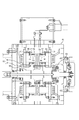
図1は本発明に係るアキシャルギャップ電動機の一実施形態を示す、アキシャルギャップ電動機の略式断面図である。
このアキシャルギャップ電動機は、図示しない複数の永久磁石をディスク状の保持部材51に周方向に設けるとともに当該保持部材51を回転軸52に連結してなるロータ53と、ロータ53にロータの中心軸線に沿って対向して配置される、ステータコア54にインシュレータ55を介してコイル56を巻装してなる、ステータ57と、
回転軸52の両端部分をラジアル軸受58とスラスト軸受59を介して回転自在に支持するとともに、ステータ57をガイド60を介して固定するケース61とから構成される。
Hereinafter, embodiments of the present invention will be described with reference to the drawings.
FIG. 1 is a schematic sectional view of an axial gap motor showing an embodiment of the axial gap motor according to the present invention.
This axial gap motor includes a
Both end portions of the
ここでは、ステータコア54は周上複数箇所に設けられ、図示しないインバータにより励磁されたコイル56により、周方向に回転磁界が形成されると、周方向に交互に極性が異なる複数の永久磁石が埋設されたロータ53は回転磁界に吸引・反発されて同期速度で回転する。
Here, the
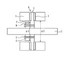
図2は本発明に係るアキシャルギャップ電動機のロータ構造の一実施形態を示す、アキシャルギャップ電動機のロータの略式断面図である。
このアキシャルギャップ電動機のロータ構造は、複数の永久磁石1をディスク状の保持部材2に周方向に設けるとともに当該保持部材2を回転軸3に連結してなるロータ4と、ロータ4にロータの中心軸線に沿って対向して配置されるステータSとからなるアキシャルギャップ電動機のロータ構造において、
回転軸3にディスク状のリブ5を、図示しないキーを介して嵌合して設けるとともに、前記保持部材2を当該リブ5の軸方向端面に、複数のボルト6を保持部材2に設けためねじに螺合して接合することにより、保持部材2を回転軸3に連結して構成される。(請求項1に相当)
さらにここでは、前記リブ5の外径φ1を、ステータSの内径φ2よりも小さくし、(請求項2に相当)リブ5の保持部材2と反対側の軸方向端面に、おもりWを挿入して付加するための複数の孔7を設けている。(請求項3に相当)
FIG. 2 is a schematic cross-sectional view of a rotor of an axial gap motor showing an embodiment of a rotor structure of an axial gap motor according to the present invention.
The rotor structure of this axial gap motor includes a rotor 4 in which a plurality of
A disc-
Further, here, the outer diameter φ1 of the
ディスク状のリブ5は、上述したキーを介した嵌合の他、回転軸に圧入する、セレーション嵌合、嵌合した後溶接する等の方法により、回転軸3に接合することもできる。さらに、ディスク状のリブ5を回転軸3と一体に加工成型することもできる。
リブ5の保持部材2に対する接合面は、例えば切削加工によりその垂直度を高めることができ、これにより、保持部材2の回転軸3に対する垂直度をさらに高めることができる。
The disc-
The joint surface of the
リブ5の外径φ1を、ステータSの内径φ2よりも小さくすることにより、図1に示すように、ステータSをリブ5の外周側にオーバーラップさせて、相互に干渉することなく設けることが可能となり、本発明のようにディスク状のリブを回転軸に設けた構造においても、ステータSとロータ4のギャップを所定の狭幅のものとすることができる。
ここで、ステータSとは、図1に示したように、ステータコアにインシュレータを介してコイルを巻装したものをいい、ステータSの内径とは、コイルおよびインシュレータを含んだステータの最小内径をいうものとする。
By making the outer diameter φ1 of the
Here, as shown in FIG. 1, the stator S refers to a stator core in which a coil is wound via an insulator, and the inner diameter of the stator S refers to the minimum inner diameter of the stator including the coil and the insulator. Shall.
リブ5の保持部材2と反対側の軸方向端面に、おもりWを付加するための複数の孔7を設けることにより、ロータの重量アンバランスを、おもりWを適宜選択して、複数の孔7のいずれかに圧入することにより、調整することが可能となる。
あるいは、おもりWを付加することに換えて、リブ5を切削加工することにより、重量アンバランスを調整することもできる。
By providing a plurality of
Alternatively, the weight imbalance can be adjusted by cutting the
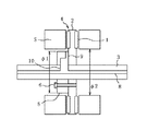
図3は本発明に係るアキシャルギャップ電動機のロータ構造の他の実施形態を示す、アキシャルギャップ電動機のロータの略式断面図である。
このアキシャルギャップ電動機のロータ構造は、複数の永久磁石1をディスク状の保持部材2に周方向に設けるとともに当該保持部材2を回転軸3に連結してなるロータ4と、ロータ4にロータの中心軸線に沿って対向して配置されるステータSとからなるアキシャルギャップ電動機のロータ構造において、
回転軸3にディスク状のリブ5を図示しないキーを介して嵌合して設けるとともに、前記保持部材2を当該リブ5の軸方向端面に、複数のボルト6を保持部材2に設けためねじに螺合して接合することにより、保持部材2を回転軸3に連結して構成される。(請求項1に相当)
FIG. 3 is a schematic sectional view of a rotor of an axial gap motor showing another embodiment of the rotor structure of the axial gap motor according to the present invention.
The rotor structure of this axial gap motor includes a rotor 4 in which a plurality of
A disc-
さらにここでは、リブ5の外径φ1を、ステータSの内径φ2よりも小さくするとともに、(請求項2に相当)回転軸3内にその中心軸線方向に延びる軸内油路8を設け、リブ5の保持部材2に面する軸方向端面に半径方向外方に延びる一以上の溝を設け、リブ5と保持部材2との間に冷却油路9を形成し、冷却油路9を軸内油路8に液密に連通する一以上の連絡油路10を回転軸内に設ける。(請求項4に相当)
Further, here, the outer diameter φ1 of the
請求項4に相当する構成とすることにより、軸内油路8内の、冷却液が、ロータ4の回転の遠心力により、連絡油路10および冷却油路9を経由して、ロータ4およびステータSのなすギャップ近傍に供給され、ロータ4の遠心力を利用したロータおよびステータの冷却を行うことができる。なお、冷却液としては、特に限定するものではないが、油または水等を用いることが可能である。
With the configuration corresponding to the fourth aspect, the coolant in the in-
また、リブ5の保持部材2に面する軸方向端面に半径方向外方に延びる一以上の溝を設け、当該溝と保持部材2との間に冷却油路9を形成することにより、ロータ4の遠心力により軸内油路8から供給された冷却油路9内の冷却液が、保持部材2に直接接触するため、後述する図4に示すような、請求項5に相当するリブ内に冷却油路を設ける構成に比して、ロータ4をより効率的に冷却することができる。
Further, by providing one or more grooves extending radially outward on the axial end face of the
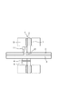
図4は本発明に係るアキシャルギャップ電動機のロータ構造のさらに他の実施形態を示す、アキシャルギャップ電動機のロータの略式断面図である。
ロータおよびステータの基本的な構成は、図2および3に示すものと同様であるため重複する部分の説明は割愛する。
ここでは、図4に示すように、回転軸3内に軸内油路8を設けるとともに、リブ5内に、半径方向外方に延びる一以上の冷却油路11を設け、該冷却油路11を前記軸内油路8に液密に連通する一以上の連絡油路12を回転軸3内に設ける。(請求項5に相当)
FIG. 4 is a schematic sectional view of a rotor of an axial gap motor showing still another embodiment of the rotor structure of the axial gap motor according to the present invention.
Since the basic configuration of the rotor and the stator is the same as that shown in FIGS. 2 and 3, the description of the overlapping parts is omitted.
Here, as shown in FIG. 4, an in-
このように、冷却油路11をリブ5内に設けることにより、図3に示したリブ5の保持部材2との接合面に溝を設ける構造に比して、リブ5と保持部材2との接合面の面積をより大きくして、接合面の中心軸に対する垂直度の調整をより容易なものとして、保持部材2の中心軸に対する垂直度を高めることができる。この構成においても、図3に示す構成と同様に、軸内油路8内の、冷却液が、ロータ4の回転の遠心力により、連絡油路12および冷却油路11を経由して、ロータ4およびステータSに供給されて、ロータの遠心力を利用したロータ4およびステータSの冷却を行うことができる。
Thus, by providing the cooling oil passage 11 in the
なお、本発明は、上記実施の形態にのみ限定されるものではなく、幾多の変形または変更が可能である。 In addition, this invention is not limited only to the said embodiment, Many deformation | transformation or a change is possible.
本発明は、アキシャルギャップ電動機のロータに用いて好適なものである。 The present invention is suitable for use in a rotor of an axial gap electric motor.
1 永久磁石
2 保持部材
3 回転軸
4 ロータ
5 リブ
6 ボルト
7 孔
8 軸内油路
9 冷却油路
10 連絡油路
11 冷却油路
12 連絡油路
S ステータ
W おもり
51 保持部材
52 回転軸
53 ロータ
54 ステータコア
55 インシュレータ
56 コイル
57 ステータ
58 ラジアル軸受
59 スラスト軸受
60 ガイド
61 ケース
DESCRIPTION OF
Claims (5)
回転軸にリブを設けるとともに、前記保持部材を当該リブの軸方向端面に接合することにより、保持部材を回転軸に連結してなるアキシャルギャップ電動機のロータ構造。 An axial consisting of a rotor in which a plurality of permanent magnets are provided in a circumferential direction on a disk-shaped holding member and the holding member is connected to a rotating shaft, and a stator that is arranged to face the rotor along the central axis of the rotor In the gap motor rotor structure,
A rotor structure of an axial gap electric motor in which a rib is provided on a rotating shaft and the holding member is joined to an axial end surface of the rib to connect the holding member to the rotating shaft.
An in-shaft oil passage is provided in the rotating shaft, and at least one cooling oil passage extending radially outward is provided in the rib, and the cooling oil passage is in fluid-tight communication with the in-shaft oil passage. The rotor structure of an axial gap electric motor according to any one of claims 1 to 3, wherein the communication oil passage is provided in a rotating shaft.
Priority Applications (4)
| Application Number | Priority Date | Filing Date | Title |
|---|---|---|---|
| JP2004111242A JP4301060B2 (en) | 2004-04-05 | 2004-04-05 | Rotor structure of axial gap motor |
| EP05007266.9A EP1585210B1 (en) | 2004-04-05 | 2005-03-30 | Rotor structure |
| US11/095,527 US7271514B2 (en) | 2004-04-05 | 2005-04-01 | Rotor structure |
| CNB2005100562940A CN100517923C (en) | 2004-04-05 | 2005-04-05 | Rotor structure |
Applications Claiming Priority (1)
| Application Number | Priority Date | Filing Date | Title |
|---|---|---|---|
| JP2004111242A JP4301060B2 (en) | 2004-04-05 | 2004-04-05 | Rotor structure of axial gap motor |
Publications (2)
| Publication Number | Publication Date |
|---|---|
| JP2005295766A true JP2005295766A (en) | 2005-10-20 |
| JP4301060B2 JP4301060B2 (en) | 2009-07-22 |
Family
ID=34909472
Family Applications (1)
| Application Number | Title | Priority Date | Filing Date |
|---|---|---|---|
| JP2004111242A Expired - Fee Related JP4301060B2 (en) | 2004-04-05 | 2004-04-05 | Rotor structure of axial gap motor |
Country Status (4)
| Country | Link |
|---|---|
| US (1) | US7271514B2 (en) |
| EP (1) | EP1585210B1 (en) |
| JP (1) | JP4301060B2 (en) |
| CN (1) | CN100517923C (en) |
Families Citing this family (4)
| Publication number | Priority date | Publication date | Assignee | Title |
|---|---|---|---|---|
| EP2061137A1 (en) * | 2007-11-19 | 2009-05-20 | Siemens Aktiengesellschaft | Method for mechanically connecting a disk motor |
| JP2009291056A (en) * | 2008-06-02 | 2009-12-10 | Ntn Corp | Motor cooling structure |
| DE102013207876A1 (en) * | 2013-04-30 | 2014-10-30 | Robert Bosch Gmbh | Electric motor with a stator and a rotor |
| GB2624859B (en) * | 2022-11-25 | 2025-05-14 | Yasa Ltd | A rotor |
Family Cites Families (17)
| Publication number | Priority date | Publication date | Assignee | Title |
|---|---|---|---|---|
| US2734140A (en) * | 1956-02-07 | parker | ||
| US3700944A (en) * | 1971-11-08 | 1972-10-24 | Ford Motor Co | Disc-type variable reluctance rotating machine |
| JPS59112402A (en) * | 1982-12-20 | 1984-06-28 | Toshiba Corp | Turntable driving device |
| JPS59127556A (en) * | 1983-01-07 | 1984-07-23 | Nippon Denso Co Ltd | Flat type rotary electric machine |
| JPS60102853A (en) * | 1983-11-08 | 1985-06-07 | Matsushita Electric Ind Co Ltd | Permanent magnet rotor of motor |
| JPS61106038A (en) * | 1984-09-28 | 1986-05-24 | Copal Denshi Kk | Construction of motor shaft |
| JPH0428195Y2 (en) * | 1985-12-12 | 1992-07-08 | ||
| JP2899998B2 (en) * | 1991-06-04 | 1999-06-02 | 松下電器産業株式会社 | FG magnet fixing device |
| US5334899A (en) * | 1991-09-30 | 1994-08-02 | Dymytro Skybyk | Polyphase brushless DC and AC synchronous machines |
| JP3367179B2 (en) | 1993-12-16 | 2003-01-14 | 松下電器産業株式会社 | Brushless motor |
| US6037696A (en) * | 1993-12-29 | 2000-03-14 | Samot Engineering (1992) Ltd. | Permanent magnet axial air gap electric machine |
| JPH08136847A (en) | 1994-11-04 | 1996-05-31 | Canon Inc | Optical deflection scanning device |
| EP0917757B1 (en) * | 1996-08-09 | 2004-10-13 | The Turbo Genset Company Limited | Rotary electrical machines |
| JP4244127B2 (en) | 2001-10-19 | 2009-03-25 | ヤマハ発動機株式会社 | Brake device for electric motorcycle |
| JP4101552B2 (en) * | 2002-04-30 | 2008-06-18 | 本田技研工業株式会社 | Electric power steering device |
| JP2004174296A (en) | 2002-11-25 | 2004-06-24 | Tokyo Parts Ind Co Ltd | Axial gap type brushless vibration motor having sensor-less drive circuit built therein |
| JP2006166679A (en) * | 2004-12-10 | 2006-06-22 | Nissan Motor Co Ltd | Stator structure of axial gap type rotating electrical machine |
-
2004
- 2004-04-05 JP JP2004111242A patent/JP4301060B2/en not_active Expired - Fee Related
-
2005
- 2005-03-30 EP EP05007266.9A patent/EP1585210B1/en not_active Ceased
- 2005-04-01 US US11/095,527 patent/US7271514B2/en not_active Expired - Lifetime
- 2005-04-05 CN CNB2005100562940A patent/CN100517923C/en not_active Expired - Fee Related
Also Published As
| Publication number | Publication date |
|---|---|
| EP1585210B1 (en) | 2017-09-13 |
| US20050218751A1 (en) | 2005-10-06 |
| JP4301060B2 (en) | 2009-07-22 |
| CN1681188A (en) | 2005-10-12 |
| US7271514B2 (en) | 2007-09-18 |
| CN100517923C (en) | 2009-07-22 |
| EP1585210A3 (en) | 2006-08-09 |
| EP1585210A2 (en) | 2005-10-12 |
Similar Documents
| Publication | Publication Date | Title |
|---|---|---|
| US10770941B2 (en) | Rotor of rotating electrical machine | |
| JP6367875B2 (en) | Rotor structure of rotating electrical machine | |
| JP2005318782A (en) | Axial gap motor cooling structure | |
| JP5087583B2 (en) | Electric motor and method of manufacturing electric motor | |
| JP2019165624A (en) | Rotator for rotating electrical machine | |
| JP7266180B2 (en) | Rotor and motor with same | |
| WO2019049397A1 (en) | Rotor cooling structure for dynamo-electric machine | |
| JP2004092910A (en) | Fluid bearing system | |
| JP2013258889A (en) | Induction motor | |
| JP2020014285A (en) | Rotary electric machine | |
| JP7287568B2 (en) | Rotor and rotor manufacturing method | |
| JP5097743B2 (en) | Electric motor | |
| JP4301060B2 (en) | Rotor structure of axial gap motor | |
| JP2013051805A (en) | Cooling structure of rotating electric machine | |
| JP2007014178A (en) | Rotor | |
| JP2020188674A (en) | Rotary electric machine | |
| JP6745212B2 (en) | Rotor and reluctance rotating electric machine | |
| JP2020188561A (en) | Rotating machine | |
| JP2006304532A (en) | Rotor structure of axial gap type rotating electrical machine | |
| JPH08116632A (en) | Rotating electric machine stator | |
| JP2023056324A (en) | Rotor, rotary electric machine, and pump | |
| JP2012147601A (en) | Outer rotor type rotary electric machine | |
| JP3671928B2 (en) | Outer rotor structure of rotating electrical machine | |
| JP2016005310A (en) | Rotor for rotating electrical machines | |
| JP2021023049A (en) | Rotor shaft for rotary electric machine, rotor core for rotary electric machine, rotor for rotary electric machine, and rotary electric machine |
Legal Events
| Date | Code | Title | Description |
|---|---|---|---|
| A621 | Written request for application examination |
Free format text: JAPANESE INTERMEDIATE CODE: A621 Effective date: 20060628 |
|
| A977 | Report on retrieval |
Free format text: JAPANESE INTERMEDIATE CODE: A971007 Effective date: 20081225 |
|
| A131 | Notification of reasons for refusal |
Free format text: JAPANESE INTERMEDIATE CODE: A131 Effective date: 20090106 |
|
| A521 | Request for written amendment filed |
Free format text: JAPANESE INTERMEDIATE CODE: A523 Effective date: 20090306 |
|
| TRDD | Decision of grant or rejection written | ||
| A01 | Written decision to grant a patent or to grant a registration (utility model) |
Free format text: JAPANESE INTERMEDIATE CODE: A01 Effective date: 20090331 |
|
| A01 | Written decision to grant a patent or to grant a registration (utility model) |
Free format text: JAPANESE INTERMEDIATE CODE: A01 |
|
| FPAY | Renewal fee payment (event date is renewal date of database) |
Free format text: PAYMENT UNTIL: 20120501 Year of fee payment: 3 |
|
| R150 | Certificate of patent or registration of utility model |
Ref document number: 4301060 Country of ref document: JP Free format text: JAPANESE INTERMEDIATE CODE: R150 Free format text: JAPANESE INTERMEDIATE CODE: R150 |
|
| A61 | First payment of annual fees (during grant procedure) |
Free format text: JAPANESE INTERMEDIATE CODE: A61 Effective date: 20090413 |
|
| FPAY | Renewal fee payment (event date is renewal date of database) |
Free format text: PAYMENT UNTIL: 20130501 Year of fee payment: 4 |
|
| FPAY | Renewal fee payment (event date is renewal date of database) |
Free format text: PAYMENT UNTIL: 20140501 Year of fee payment: 5 |
|
| LAPS | Cancellation because of no payment of annual fees |