JP2005295903A - Spraying boom support device for chemical spraying vehicle - Google Patents
Spraying boom support device for chemical spraying vehicle Download PDFInfo
- Publication number
- JP2005295903A JP2005295903A JP2004117771A JP2004117771A JP2005295903A JP 2005295903 A JP2005295903 A JP 2005295903A JP 2004117771 A JP2004117771 A JP 2004117771A JP 2004117771 A JP2004117771 A JP 2004117771A JP 2005295903 A JP2005295903 A JP 2005295903A
- Authority
- JP
- Japan
- Prior art keywords
- boom
- spraying
- bracket
- side boom
- chemical
- Prior art date
- Legal status (The legal status is an assumption and is not a legal conclusion. Google has not performed a legal analysis and makes no representation as to the accuracy of the status listed.)
- Pending
Links
- 239000000126 substance Substances 0.000 title claims abstract description 59
- 238000005507 spraying Methods 0.000 title claims abstract description 45
- 239000007921 spray Substances 0.000 claims description 10
- 238000003892 spreading Methods 0.000 abstract description 3
- 239000000243 solution Substances 0.000 description 20
- 239000008155 medical solution Substances 0.000 description 8
- 238000009826 distribution Methods 0.000 description 4
- 239000007788 liquid Substances 0.000 description 4
- 238000005096 rolling process Methods 0.000 description 4
- 238000010586 diagram Methods 0.000 description 3
- 238000000034 method Methods 0.000 description 3
- 230000008602 contraction Effects 0.000 description 2
- 239000003814 drug Substances 0.000 description 2
- 230000000694 effects Effects 0.000 description 2
- XLYOFNOQVPJJNP-UHFFFAOYSA-N water Substances O XLYOFNOQVPJJNP-UHFFFAOYSA-N 0.000 description 2
- 235000010469 Glycine max Nutrition 0.000 description 1
- 244000068988 Glycine max Species 0.000 description 1
- 230000009194 climbing Effects 0.000 description 1
- 238000009792 diffusion process Methods 0.000 description 1
- 239000006185 dispersion Substances 0.000 description 1
- 238000006073 displacement reaction Methods 0.000 description 1
- 238000009313 farming Methods 0.000 description 1
- 239000012530 fluid Substances 0.000 description 1
- 230000005484 gravity Effects 0.000 description 1
- 230000002452 interceptive effect Effects 0.000 description 1
- 230000002265 prevention Effects 0.000 description 1
- 230000001105 regulatory effect Effects 0.000 description 1
- 238000004904 shortening Methods 0.000 description 1
- 238000003860 storage Methods 0.000 description 1
- 239000010902 straw Substances 0.000 description 1
- 239000013585 weight reducing agent Substances 0.000 description 1
Images
Landscapes
- Catching Or Destruction (AREA)
- Special Spraying Apparatus (AREA)
Abstract
【課題】サイドブームを左右水平方向に開いた時に生じる前方及び後方からの荷重に対してして揺れを緩和することができる薬液散布作業車の散布ブーム支持装置を提供すること。
【解決手段】センターブーム43の左右両端部に上下方向に伸びる第一の回動軸33bを有するブラケット33を介してサイドブーム44を回動自在に連結すると共に、前記ブラケット33には、前記サイドブーム44をセンターブーム43に対して左右に広げるためのサイドブーム開閉油圧シリンダ30と、前記サイドブーム44を第二の回動軸33aを中心に一方向に付勢するスプリング34及びストッパ37を設け、油圧シリンダ30を第三の回動軸32aを有するブラケット32を介してセンターブーム43に連結し、ブラケット32には油圧シリンダ30を一方向へ付勢するスプリング35及びストッパ36を設けた薬液散布作業車の散布ブーム支持装置である。
【選択図】図3Disclosed is a spraying boom supporting device for a chemical spraying work vehicle, which can relieve shaking against a load from the front and rear that occurs when a side boom is opened in the horizontal direction.
A side boom is pivotally connected to a bracket 33 via a bracket 33 having a first pivot shaft 33b extending in the vertical direction at both left and right end portions of a center boom 43. A side boom opening / closing hydraulic cylinder 30 for expanding the boom 44 to the left and right with respect to the center boom 43, and a spring 34 and a stopper 37 for urging the side boom 44 in one direction around the second rotation shaft 33a are provided. The hydraulic cylinder 30 is connected to the center boom 43 via a bracket 32 having a third rotating shaft 32a, and the bracket 32 is provided with a spring 35 and a stopper 36 for urging the hydraulic cylinder 30 in one direction. It is a spreading boom support device of a work vehicle.
[Selection] Figure 3
Description
本発明は、薬液散布装置を備えた作業車に関し、特に薬液散布の散布ブームの構造に関する。 The present invention relates to a work vehicle equipped with a chemical solution spraying device, and more particularly to the structure of a spraying boom for chemical solution spraying.
圃場で生育中の作物に対して走行しながら薬液を散布する薬液散布作業車が用いられている。この薬液散布作業車は、その車体の前部に、平行リンク形態のリフトリンクを装着し、この前部のヒッチブラケットとロワリンクとの間にリフトシリンダを設けて、このリフトシリンダの伸縮によってリフトリンクを昇降駆動させる構成とし、このリフトリンクにヒッチブラケットを介して薬液散布の散布ブームを取り付けている。また、前記薬液散布用のブームは中央のセンターブームとその両側に開閉自在のサイドブームを取り付けた構成となっている。 There is used a chemical solution spraying vehicle for spraying a chemical solution while traveling on a growing crop in a field. This chemical spray vehicle is equipped with a parallel link type lift link at the front of the vehicle body, and a lift cylinder is provided between the front hitch bracket and the lower link. And a spray boom for spraying chemicals is attached to the lift link via a hitch bracket. Moreover, the said chemical | medical solution dispersion | distribution boom becomes a structure which attached the center boom in the center, and the side boom which can be opened and closed to the both sides.
センターブームとサイドブームを用いて薬液散布作業車が薬液散布を行う場合には、サイドブームを左右の水平方向に長く突き出した状態で行うため、重いサイドブーム部分に外力がかかると、揺れが大きくなりサイドブーム基部側の平行リンク機構が捻れたり、薬液噴霧作業中にサイドブームの水平が保ち難いことがあった。そのための改良技術として下記特許文献1に記載の発明は、平行リンク機構部分を補強して、サイドブームの揺れの防止対策をしている。
前記した特許文献に記載の発明においては、平行リンク機構部分を補強するサイドブームの揺れ防止構造はサイドブームを左右水平方向に開いたときに生じる作業車の後方へ向けての荷重(後方荷重)に対しては効果的であるが、作業車の前方へ向けての荷重(前方荷重)に対する揺れを緩和することができていなかった。 In the invention described in the above-mentioned patent document, the side boom swing prevention structure that reinforces the parallel link mechanism portion is a load toward the rear of the work vehicle that occurs when the side boom is opened in the horizontal direction (rear load). Although effective against the above, it was not possible to alleviate the shaking with respect to the load toward the front of the work vehicle (forward load).
本発明の課題は、サイドブームを左右水平方向に開いたときに生じる前方及び後方からの荷重に対して揺れを緩和することができる薬液散布作業車の散布ブーム支持装置を提供することである。 The subject of this invention is providing the spreading | diffusion boom support apparatus of the chemical | medical solution spreading work vehicle which can relieve | shake a shake | fluctuation with respect to the load from the front and back which arises when a side boom is opened in the left-right horizontal direction.
上記課題は次の解決手段で解決される。
請求項1記載の発明は、車体の前方または後方に薬液散布用のセンターブーム(43)を設け、このセンターブーム(43)の左右両端部に上下方向に伸びる第一の回動軸(33b)を有するブラケット(33)を介して薬液散布用のサイドブーム(44)を回動自在に連結すると共に、前記ブラケット(33)には、前記サイドブーム(44)をセンターブーム(43)に対して左右に広げるためのサイドブームアクチュエータ(30)と、前記サイドブーム(44)をセンターブーム(43)に対し第二の回動軸(33a)を中心に一方向に付勢する付勢部材(34)及び前記付勢されたサイドブーム(44)を位置決めするストッパ(37)を設け、更に前記アクチュエータ(30)を上下方向に伸びる第三の回動軸(32a)を有するブラケット(32)を介して薬液散布用のセンターブーム(43)に連結し、前記ブラケット(32)には、前記アクチュエータ(30)を一方向へ付勢する付勢手段(35)及び前記付勢されたブラケット(32)を位置決めするストッパ(36)を設けた薬液散布作業車の散布ブーム支持装置である。
The above problem is solved by the following means.
According to the first aspect of the present invention, a center boom (43) for spraying a chemical solution is provided in front of or behind the vehicle body, and a first rotating shaft (33b) extending vertically at both left and right ends of the center boom (43). A side boom (44) for spraying a chemical solution is rotatably connected via a bracket (33) having a side, and the side boom (44) is connected to the center boom (43) to the bracket (33). A side boom actuator (30) for expanding to the left and right, and a biasing member (34) for biasing the side boom (44) to the center boom (43) in one direction around the second rotation shaft (33a). And a stopper (37) for positioning the biased side boom (44), and further has a third rotating shaft (32a) for extending the actuator (30) in the vertical direction. The bracket (32) is connected to the center boom (43) for spraying the chemical solution, and the bracket (32) has a biasing means (35) for biasing the actuator (30) in one direction and the biasing force. This is a spraying boom support device for a chemical spraying work vehicle provided with a stopper (36) for positioning the bracket (32).
請求項1記載の発明によれば、外力でサイドブーム44が前方及び後方に揺らされても、サイドブーム44にかかる外力を受け止める保持部材があるので、サイドブーム44の大きな振れを小さくすることができる。
According to the first aspect of the present invention, even if the
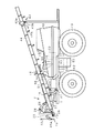
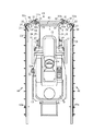
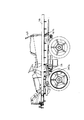
本発明の実施の形態を図面と共に説明する。図1に薬液散布装置を前部に取り付けた薬液散布作業車の側面図を示し、図2には薬液散布作業装置部分の平面図を示す。なお、本明細書では薬液散布作業車の前進方向に向かった左右方向をそれぞれ左、右という。 Embodiments of the present invention will be described with reference to the drawings. FIG. 1 shows a side view of a chemical spraying work vehicle with the chemical spraying device attached to the front, and FIG. 2 shows a plan view of the chemical spraying device part. In the present specification, the left and right directions in the forward direction of the chemical spray vehicle are referred to as left and right, respectively.
薬液散布作業車の車体1は、前輪12及び後輪13を軸装するアクスルハウジングをローリング自在に支持する。また、ハンドルポスト59により支持されたステアリングハンドル14の回転操作により前輪12を操向すると共にボンネット15下のエンジン(図示せず)によって伝動走行される。この車体1には操縦席17の後部から左右両側にわたって囲うように形成された薬液タンク18を車体に対し着脱自在に搭載し、この薬液タンク18内の薬液を前側に設けられる散布ブーム19へ圧送する防除ポンプ20が車体1の操縦席17下方に設けられている。
The vehicle body 1 of the chemical solution spraying work vehicle supports an axle housing on which the front wheels 12 and the
操縦席17の左側下方でフロア54の上方に位置する薬液タンク18の左側部には、オペレータ一人が乗り降りできる程度の凹部Sが設けられ、該凹部Sの底面にタンク側ステップ50が設けられている。タンク側ステップ50の外側下方には、本機側ステップ53が設けられている。この本機側ステップ53は、上面53Aがフロア54・薬液タンク18の底面とほぼ同一高さとなる位置にある。
On the left side of the
本機側ステップ53の下方には、フロア54から吊り下げ式に設置された梯子部材55が設けられている。梯子部材55は任意の段数、例えば2段のステップを有している。これらの梯子部材55、本機側ステップ53及びタンク側ステップ50は所定の間隔で配置されている。このような構成によりオペレータは、梯子部材55のステップ、本機側ステップ53及びタンク側ステップ50を順に登ることにより、安全かつ容易に操縦席17に到達して乗車できる。
Below the machine-
本機のフロア54に該薬液タンク18を搭載する自走型薬液散布作業車において、薬液タンク18は本機ダッシュパネル56付近まで前方に突出している。一方、薬液タンク18は上面視してオペレータの足元まで完全に覆い囲った略コの字状の構造を有している。このような構造により薬液タンク18の高さを増加させずにタンク容量を増大させるとともに後進時の見通しを確保できる。また、薬液タンク18を前方に長くすることにより、薬液タンク内水量の変位による機体の重心移動を小さく抑え、薬液散布作業時の機体バランスを安定させ、走行性能を高めることができ、機体が後傾して沈没するという事態を回避できる。
In the self-propelled chemical solution spraying vehicle in which the
なお、図2では薬液タンク18の上面が略コ形状の略直方体形状のものを図示しているが、これに限定されず、タンクステップを有する形状であれば任意の形状にすることができる。
In FIG. 2, the
薬液タンク18の先端部形状は、フロア54のフロントに上方へ浮き上がるように湾曲させた傾斜部51と密着するように形成されている。従って、薬液タンク18を後方から前方へ移動させて傾斜部51で合致させて止めることができる。このような構造により前輪12の横揺れ等によるタイヤとタンク18の干渉を防止でき、薬液タンク18の本機のフロア54上での接地性を高め、タンク18の安定性を高めることができる。
The tip shape of the
前記車体1の前部には、ボンネット15の左右両側部に支持されたリフトリンク3が取り付けられている。リフトリンク3は、アッパリンク24とロワリンク25を平行状に配置して、この前端部間をヒッチブラケット4で連結し、後端部間を直立した支柱23に軸支して平行リンク形態に構成され、この平行リンクが昇降シリンダ27、27により先端部が昇降移動することで散布ブーム19の薬剤散布高さを調節することができる。
At the front part of the vehicle body 1,
ヒッチブラケット4の下端部には機体左右方向に伸びるセンターブーム43を取り付けている。またその左右端部に上方に突出したシリンダ取付支柱26が設けられ、シリンダ取付支柱26の上端には電気的に作動制御される油圧タンク付ソレノイドバルブ28を介して伸縮するローリングシリンダである上下シリンダ(ローリングシリンダ)29の上端が取り付けられ、上下シリンダ29の下端にはサイドブーム44が回動自在に取り付けられている。従って上下シリンダ29の伸縮によりサイドブーム44が昇降される。
A
前記散布ブーム19は、センターブーム43と、このセンターブーム43の外側に折畳可能に連結されるサイドブーム44とから構成され、各々薬剤噴霧用の噴霧ノズル45(45a、45b)が一定間隔で配置されている。
The
サイドブーム44はシリンダ取付支柱26を介してセンターブーム43に取り付けられているが、サイドブーム44はセンターブーム43に設けられた開閉シリンダ30により開閉される。
The
指標ロッド52(図1)は、センターブーム43の中央付近領域から上方に向けて垂直に突出して設けられたロッドである。該指標ロッド52の上端にはLED等からなるランプが付設されており、後述する自動水平制御動作の開始と同時にランプが点灯する。なお、指標ロッド52の下端において、作動機構等と連動して自動水平制御中に回転等するようにしても良い。このような構成によりオペレータにブーム43、44の制御状態を認知させることができ、ブーム43、44の誤操作を回避でき、散布作業時に自動水平スイッチをONにすることを忘れ、ロングブーム(サイドブーム44)の先端のノズル45bが作物と接触し、破損するという不具合を回避できる。
The index rod 52 (FIG. 1) is a rod provided so as to protrude vertically upward from an area near the center of the
ここで自動水平制御動作とは、開閉シリンダ30、30によりサイドブーム44、44をセンターブーム43の延長線上の水平方向(機体の進行方向に向かって左右方向)に開き、さらに上下シリンダ29、29であるローリングシリンダを最大限伸ばした際に、サイドブーム44、44が地面に対して水平状態になるように制御することをいう。具体的には、傾斜地を走行中に薬剤散布ブーム19のサイドブーム44を開いていても上下シリンダ29を一方のサイドブーム44をリフトさせ、他方のサイドブーム44をダウンさせることで開いたサイドブーム44を傾斜地に対して平行になるようにして、地面に衝突させないようにする。
Here, the automatic horizontal control operation means that the opening and
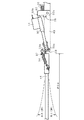
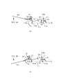
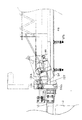
図3はサイドブーム44がセンターブーム43の左右水平方向に開いたときの開閉機構部分の平面図、図4は本実施例のサイドブーム44が開いた時の開閉機構部分の簡略平面図である。なお、図3と図4には左側のサイドブーム44がセンターブーム43に対して水平方向に開いたときの開閉機構部分を示すが、右側のサイドブーム44がセンターブーム43に対して水平方向に開いたときの開閉機構部分も同様であることはいうまでもない。
3 is a plan view of the opening / closing mechanism when the
次にサイドブーム44の開閉機構を説明する。
センターブーム43の両端部には開閉ヒンジ33が回動支点33bを中心に回動自在に取り付けられている。また開閉ヒンジ33の回動支点33b近傍には開閉シリンダ30の先端部が回動自在に連結しており、回動支点33aの近傍には引張スプリング34の一端が連結され、引張スプリング34の他端はサイドブーム44の上面に連結されている。
Next, the opening / closing mechanism of the
Opening and closing hinges 33 are attached to both ends of the
また、開閉シリンダ30の基部側は開閉シリンダブラケット32の一端に回動支点32bを中心に回動自在に取り付けられている。開閉シリンダブラケット32の他端側の基部はセンターブーム43に回動支点32aを有する。該開閉シリンダブラケット32の内面はセンターブーム43の前面に設けられた安全スプリング35に当接する位置に取り付けられている。また開閉シリンダブラケット32の前記スプリング35への当接面とは反対側の側面はセンターブーム43に設けられたストッパ36に当接し得るようにセンターブーム43に取り付けられている。
また、サイドブーム44の回動基部にも開閉ヒンジ33に当接し得る位置にストッパ37が設けられている。
In addition, the base side of the opening /
Further, a
従って、図4(a)に示すように外力でサイドブーム44が前方に揺らされると、サイドブーム44が開閉ヒンジ33の回動支点33bを中心に回動しながら変形するが、ストッパ37と開閉ヒンジ33が当接することで、この変形力を支える。このとき開閉ヒンジ33の回動に連動して開閉シリンダ30と開閉シリンダブラケット32もスプリング35を圧縮して前記サイドブーム44の変形力を支えるが、該スプリング35はストッパ36に付勢しなくなるだけである。
Therefore, as shown in FIG. 4A, when the
ストッパ37と開閉ヒンジ33の当接と開閉シリンダブラケット32とスプリング35との当接でサイドブーム44の大きな変形を防ぐことができる。
A large deformation of the
一方、図4(b)に示すように外力でサイドブーム44が後方に揺らされると、サイドブーム44が開閉ヒンジ33の回動支点33aを中心に回動しながら変形してスプリング34が伸び、ストッパ37は開閉ヒンジ33と当接しなくなり、開閉ヒンジ33の両端は回動して前記外力を逃がし、また開閉シリンダ30と開閉シリンダブラケット32が開閉ヒンジ33の回動に連動して開閉シリンダブラケット32がストッパ36に押圧される。
この開閉シリンダブラケット32とストッパ36との当接でサイドブーム44の大きな変形を防ぐことができる。
On the other hand, as shown in FIG. 4B, when the
A large deformation of the
大豆などの作物に薬液散布を行う場合などには、畝を連続して越える場合にサイドブーム44が大きく揺れることがある。特に作業車が断続的に進行する場合にはサイドブーム44が前後方向に激しく揺動する。後方へのサイドブーム44の変形は従来の装置でも安全スプリング効果で緩和されているが、前方へのサイドブーム44の揺れによる変形に対しては安全対策がなかった。
For example, when spraying chemicals on crops such as soybeans, the
しかし、上記本実施例のブーム開閉シリンダブラケット32と二つのスプリング36、37を備えた構成により前後方向へのサイドブーム44の変形荷重に対するブームの歪を緩和することができる。
However, the boom opening /
またサイドブーム44を使用しないときはブーム受け40に収納・載置される。ブーム受け40は回転軸41を共有するブーム受け部40aとその支持部40bからなり、機体後部の両側面に設けられ、左右のサイドブーム44、44の後端部をそれぞれ支持する。
When the
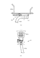
ブーム受け部40aは図5(a)の正面図と図5(b)の側面図に示すように「コ」の字の部材であり、「コ」の字の両側先端を末広がり状にした部材であり、「コ」の字の底部に設けられた回動軸41をブーム受け支持部40bと共有している。
As shown in the front view of FIG. 5 (a) and the side view of FIG. The rotating
ブーム受け支持部40bのブーム受け部40aの底面に対向する先端部は水平方向に向いており、前記回転軸41を支持片42で回動自在に支持している。そのため、サイドブーム44がブーム受け部40aに向けて下降して収納されるとき、必ずサイドブーム44とブーム受け部40aの傾斜角度を同じにすることができる。また、ブーム受け部40aにはサイドブーム移動規制用のリミットスイッチ46を設けているので、サイドブーム44がブーム受け部40aに収納されると、前記スイッチ46がオンされて、サイドブーム44の移動が規制される。
A tip end portion of the boom receiving
本来は、サイドブーム44の収納作業には順序があって、ブーム上下シリンダ29でサイドブーム44を最上げ状態にして、次にサイドブーム44を開閉シリンダ30で閉じた後に、上下シリンダ29でサイドブーム44を下げてブーム受け40に載置する。しかし、ユーザーによってはサイドブーム44の上下シリンダ29の上下動作だけによってブーム受け40にサイドブーム44を収納する操作をするため、ブーム44とブーム受け40の傾斜角度が異なり、リミットスイッチ46がオンされずにブーム44を損傷又は屈曲させてしまう場合があった。
Originally, the storage work of the
しかし、上記した図5に示すブーム受け40の構成により、サイドブーム44のブーム受け部40aへの収納時には、必ずサイドブーム44とブーム受け部40aの傾斜角度が同じになるので、どのような作業手順でサイドブーム44がブーム受け40に収納されても、確実にサイドブーム44の作動が規制されるのでサイドブーム44とブーム受け40が損傷することを防止できる。
However, with the configuration of the
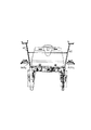
図6の車体側面図、図7の車体背面図にはブーム受け40の他にサイドブーム受け140を設けた構成を示す。
サイドブーム44を支持するブーム受け140を機体側面の前後に設け、ブーム受け140の前側ブーム受け140aはフロア54より左右水平方向に突出させ、後側ブーム受け140bは前記前側のブーム受け140aと同じ高さで車体1から左右水平方向に突出させて設けたものである。
The vehicle body side view of FIG. 6 and the vehicle body rear view of FIG. 7 show a configuration in which a side boom receiver 140 is provided in addition to the
Boom receivers 140 for supporting the
従来サイドブーム44の着脱は、一人がサイドブーム44の始端部を持ち、もう一人が終端部を持って行っており、複数の作業者が必要であり、しかもサイドブーム44は重量が重く、この着脱作業が容易ではなかった。しかし、上記サイドブーム受け140は、ほぼ水平状態のサイドブーム44を載置できるので、一人の作業者で重いサイドブーム44の着脱作業を安全に行うことができる。
Conventionally, the
こうして、通常のサイドブーム44の収納及び走行時にはブーム受け40を使用し、サイドブーム44の着脱作業時は下方の前記サイドブーム受け140を使用することができる。
Thus, the
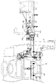
本発明の他の実施例のサイドブーム44の上下機構を図8の車体正面図、図9の車体正面拡大図に示す。
本実施例はサイドブーム44を上下させるための昇降(上下)用油圧シリンダ29を図1に示す上方よりの吊り下げ式ではなく、センタブーム43のほぼ左右水平方向に設けたものである。
The vertical mechanism of the
In this embodiment, the lifting / lowering (up / down)
サイドブーム44の基端部側に設けたマスト126の上方部にサイドブーム44の上下方向への回動支点126aを設け、サイドブーム昇降(上下)用油圧シリンダ29の基点取付部126bをマスト126の下端部に設ける。また、前記上下シリンダ29の先端取り付け部をサイドブーム44上の支持片144に設け、上下シリンダ29の伸縮によってサイドブーム44が昇降(上下)する構造とした。油圧シリンダ29をサイドブーム44の水平線上の前方部に位置させたことに特徴がある。
A
また、サイドブーム44の左右水平方向への展開時に、マスト126の前面とサイドブーム支持ブラケット132の基端部端面が接触し、センターブーム43とサイドブーム44が水平に一直線になるようマスト126の側面とサイドブーム支持ブラケット132の基端部端面とでサイドブーム44の下降位置規制をした構成である。
In addition, when the
上下シリンダ29を縮めてマスト126の側面とサイドブーム支持ブラケット132の基端部端面を互いに強く接触させることで、油圧シリンダ29の取付部及びサイドブーム44の回動支点のあそび(ガタ)が吸収され、前記あそびによるサイドブーム44の揺れが小さくなり、特にサイドブーム44の上下の揺れが無くなる。
By contracting the upper and
また、薬液散布作業開始前にサイドブーム44を展開させるが、サイドブーム44の上下位置の高さが前記マスト126の側面とサイドブーム支持ブラケット132の基端部端面の接触により、一定値に決まるので、左右のサイドブーム44の高さが異なることが無く、均一な薬液散布精度も向上する。
Further, the
図1に示すサイドブーム44の昇降用のシリンダ29は上方より吊り下げ式に設けているためブームセンターピボット部Aからの距離が遠く、ブーム作業時に大きな偶力が発生して、サイドブーム44を揺らす要因になる。また、この方式では、シリンダ取付支柱26も上方へ長くなる構成となり、重量が大幅にアップし、これもサイドブーム44を揺らす要因になっているが、これらの不具合も、上記図8、図9に示す構成では解消される。
The
このように図8と図9に示す構成によれば、大幅な重量低減と、偶力発生低減効果が大きく、サイドブーム44の揺れを大きく抑制でき、より高速での防除作業が実現可能で、自動水平性能も大幅に良くなる。
Thus, according to the configuration shown in FIG. 8 and FIG. 9, the significant weight reduction and the couple generation reduction effect are large, the swing of the
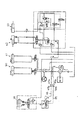
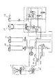
図10にはブーム自動上下シリンダ29)と前後輪操舵用シリンダ60、61と後部作業機用水平シリンダ62と後部作業機用昇降シリンダ63の作動油圧回路図を示す。
FIG. 10 is a hydraulic circuit diagram of the boom automatic vertical cylinder 29), front and rear
従来の油圧回路では、約15mのサイドブーム44の上下シリンダ29に常時オイルが流れている。そのため、エンジンのアイドリング時に作業機(この作業車に図示しない圃場耕耘用の作業機を連結することがある)を上昇させることができない。作業機を上昇させるためにはエンジンの回転数を1,400rpmにまで上げる必要がある。従って、エンジンのアイドリング時に作業機を上昇させるためには油圧回路を流れているオイルの量を、さらに1.5リットル増やす必要がある。
In the conventional hydraulic circuit, oil always flows through the upper and
しかし、図11に示す構成で油路を短くすることで上記不具合を解消できる。すなわち、サイドブーム44の上下シリンダ29にオイルを循環させる油路66の途中に設けたカプラ67a、67b及び油路69の途中に設けたカプラ70a、70bをそれぞれ外して油路66、69の連通を断ち、それぞれ油路66、69のカプラ67a、70a間及び油路66、69のカプラ67b、70bの間を接続すると、作業機を上昇させるための油圧回路のオイルの流路が短くなり、エンジンのアイドリング時でも作業機を上昇させるためのオイル圧力が十分得られる。
前記カプラ67a、67b及びカプラ70a、70bをワンタッチカプラとすると、油路の切替作業も簡単に行える。
However, the above problem can be solved by shortening the oil passage with the configuration shown in FIG. That is, the couplers 67a and 67b provided in the middle of the
If the couplers 67a and 67b and the
本発明は、薬液散布装置を備えた作業車に関し、例えば、薬液、散水等の流体を蓄えた散布装置を備えた作業車に適用できる。 The present invention relates to a work vehicle provided with a chemical solution spraying device, and can be applied to, for example, a work vehicle provided with a spraying device that stores a fluid such as a chemical solution or water spray.
1 車体 3 リフトリンク
4 ヒッチブラケット 12 前輪
13 後輪 14 ステアリングハンドル
15 ボンネット 17 操縦席
18 薬液タンク 19 散布ブーム
20 防除ポンプ 23 支柱
24 アッパリンク 25 ロワリンク
26 シリンダ取付支柱 27 昇降シリンダ
28 ソレノイドバルブ 29 上下シリンダ(ローリングシリンダ)
30 開閉シリンダ 32 開閉シリンダブラケット
33 開閉ヒンジ
32a、32b、33a、33b 回動支点
34 引張スプリング 35 安全スプリング
36、37 ストッパ 40 ブーム受け
40a ブーム受け部 40b ブーム支持部
41 ブーム受け回転軸 42 支持片
43 センターブーム 44 サイドブーム
45a、45b 噴霧ノズル 46 リミットスイッチ
50 タンク側ステップ 51 フロアの傾斜部
S 凹部(乗降用凹部) 52 指標ロッド
53 本機側ステップ 54 フロア
55 梯子部材 56 ダッシュパネル
59 ハンドルポスト 60 前輪操舵用シリンダ
61 後輪操舵用シリンダ 62 後部作業機用水平シリンダ
63 作業機用昇降シリンダ 66、69 油路
67a、67b、70a、70b カプラ
126 マスト 126a 回動支点
126b シリンダ基点取付部 132 サイドブーム支持ブラケット
140 サイドブーム受け 144 支持片
DESCRIPTION OF SYMBOLS 1
DESCRIPTION OF
Claims (1)
前記ブラケット(33)には、前記サイドブーム(44)をセンターブーム(43)に対して左右に広げるためのサイドブームアクチュエータ(30)と、前記サイドブーム(44)をセンターブーム(43)に対し第二の回動軸(33a)を中心に一方向に付勢する付勢部材(34)及び前記付勢されたサイドブーム(44)を位置決めするストッパ(37)を設け、
更に前記アクチュエータ(30)を上下方向に伸びる第三の回動軸(32a)を有するブラケット(32)を介して薬液散布用のセンターブーム(43)に連結し、
前記ブラケット(32)には、前記アクチュエータ(30)を一方向へ付勢する付勢手段(35)及び前記付勢されたブラケット(32)を位置決めするストッパ(36)を設けたことを特徴とする薬液散布作業車の散布ブーム支持装置。 A center boom (43) for spraying a chemical solution is provided in front of or behind the vehicle body, and a bracket (33) having first rotating shafts (33b) extending in the vertical direction at both left and right ends of the center boom (43). The side boom (44) for spraying the chemical solution is pivotally connected,
The bracket (33) includes a side boom actuator (30) for expanding the side boom (44) to the left and right with respect to the center boom (43), and the side boom (44) to the center boom (43). A biasing member (34) for biasing in one direction around the second rotation shaft (33a) and a stopper (37) for positioning the biased side boom (44);
Furthermore, the actuator (30) is connected to a center boom (43) for spraying chemicals via a bracket (32) having a third rotating shaft (32a) extending in the vertical direction,
The bracket (32) is provided with a biasing means (35) for biasing the actuator (30) in one direction and a stopper (36) for positioning the biased bracket (32). A spray boom support device for a chemical spray vehicle.
Priority Applications (1)
| Application Number | Priority Date | Filing Date | Title |
|---|---|---|---|
| JP2004117771A JP2005295903A (en) | 2004-04-13 | 2004-04-13 | Spraying boom support device for chemical spraying vehicle |
Applications Claiming Priority (1)
| Application Number | Priority Date | Filing Date | Title |
|---|---|---|---|
| JP2004117771A JP2005295903A (en) | 2004-04-13 | 2004-04-13 | Spraying boom support device for chemical spraying vehicle |
Publications (1)
| Publication Number | Publication Date |
|---|---|
| JP2005295903A true JP2005295903A (en) | 2005-10-27 |
Family
ID=35328198
Family Applications (1)
| Application Number | Title | Priority Date | Filing Date |
|---|---|---|---|
| JP2004117771A Pending JP2005295903A (en) | 2004-04-13 | 2004-04-13 | Spraying boom support device for chemical spraying vehicle |
Country Status (1)
| Country | Link |
|---|---|
| JP (1) | JP2005295903A (en) |
Cited By (10)
| Publication number | Priority date | Publication date | Assignee | Title |
|---|---|---|---|---|
| JP2014230524A (en) * | 2013-05-29 | 2014-12-11 | 井関農機株式会社 | Chemical liquid spraying vehicle |
| JP2014236703A (en) * | 2013-06-07 | 2014-12-18 | カヤバ工業株式会社 | Boom sprayer and boom damping device |
| JP2014236704A (en) * | 2013-06-07 | 2014-12-18 | カヤバ工業株式会社 | Boom sprayer and boom support device |
| WO2016006434A1 (en) * | 2014-07-11 | 2016-01-14 | Kyb株式会社 | Boom vibration control device and boom sprayer |
| CN106386760A (en) * | 2016-09-13 | 2017-02-15 | 江苏大学 | Multifunctional electrostatic spraying device |
| CN107624741A (en) * | 2017-11-07 | 2018-01-26 | 叶建望 | A kind of mixed uniformly swing type pesticide spraying device of decoction |
| CN108077228A (en) * | 2018-02-08 | 2018-05-29 | 温州科技职业学院 | A kind of gard watering device |
| CN108719251A (en) * | 2018-05-30 | 2018-11-02 | 王书杭 | A kind of agricultural chemical spraying device |
| CN110241703A (en) * | 2019-07-08 | 2019-09-17 | 安徽开源路桥有限责任公司 | Road surface pit slot side wall spray coating mechanical and the pit slot pavement construction method |
| KR20240014655A (en) * | 2022-07-25 | 2024-02-02 | 고우판 | spray device |
-
2004
- 2004-04-13 JP JP2004117771A patent/JP2005295903A/en active Pending
Cited By (13)
| Publication number | Priority date | Publication date | Assignee | Title |
|---|---|---|---|---|
| JP2014230524A (en) * | 2013-05-29 | 2014-12-11 | 井関農機株式会社 | Chemical liquid spraying vehicle |
| JP2014236703A (en) * | 2013-06-07 | 2014-12-18 | カヤバ工業株式会社 | Boom sprayer and boom damping device |
| JP2014236704A (en) * | 2013-06-07 | 2014-12-18 | カヤバ工業株式会社 | Boom sprayer and boom support device |
| WO2016006434A1 (en) * | 2014-07-11 | 2016-01-14 | Kyb株式会社 | Boom vibration control device and boom sprayer |
| JP2016019478A (en) * | 2014-07-11 | 2016-02-04 | Kyb株式会社 | Boom vibration control device and boom sprayer |
| CN106386760A (en) * | 2016-09-13 | 2017-02-15 | 江苏大学 | Multifunctional electrostatic spraying device |
| CN107624741A (en) * | 2017-11-07 | 2018-01-26 | 叶建望 | A kind of mixed uniformly swing type pesticide spraying device of decoction |
| CN108077228A (en) * | 2018-02-08 | 2018-05-29 | 温州科技职业学院 | A kind of gard watering device |
| CN108719251A (en) * | 2018-05-30 | 2018-11-02 | 王书杭 | A kind of agricultural chemical spraying device |
| CN110241703A (en) * | 2019-07-08 | 2019-09-17 | 安徽开源路桥有限责任公司 | Road surface pit slot side wall spray coating mechanical and the pit slot pavement construction method |
| CN110241703B (en) * | 2019-07-08 | 2024-01-23 | 安徽开源路桥有限责任公司 | Road surface pit slot side wall spraying machine and pit slot road surface construction method |
| KR20240014655A (en) * | 2022-07-25 | 2024-02-02 | 고우판 | spray device |
| KR102834273B1 (en) * | 2022-07-25 | 2025-07-15 | 고우판 | spray device |
Similar Documents
| Publication | Publication Date | Title |
|---|---|---|
| EA024582B1 (en) | Agricultural spraying machine and method for controlling such a machine while spraying a phytosanitary liquid | |
| CN105472965A (en) | Work-apparatus orientation control device | |
| JP2018057331A (en) | Grass mower | |
| JP7274791B2 (en) | lawn mower | |
| JP2020012255A (en) | Construction machinery | |
| JP2023133388A5 (en) | ||
| US6637136B2 (en) | Backhoe unit detachably attached to a tractor | |
| JP2023133388A (en) | Self-propelled chemical sprayer | |
| JP2010051274A (en) | Control working machine | |
| JP4143861B2 (en) | Drug spraying work vehicle | |
| JP2012175918A (en) | Chemical spraying working vehicle | |
| AU2020203721B2 (en) | Hitch Mechanism | |
| JP2001269106A (en) | Control solution spraying boom support device | |
| KR20060043718A (en) | Work car with front loader | |
| JP2005138043A (en) | Chemical spraying work vehicle | |
| JP4317100B2 (en) | Excavator | |
| JP6079690B2 (en) | Chemical spraying work vehicle | |
| JP2009261328A (en) | Pest control machine | |
| JP2019076043A (en) | Riding type chemical spreader | |
| JP2006088094A (en) | Chemical spraying work vehicle | |
| JP2006087387A (en) | Drug spraying work vehicle | |
| JP2003334477A (en) | Chemical spraying vehicle | |
| JPH0538220A (en) | Bed lift device for truck | |
| JP2006061788A (en) | Spraying control device for spraying vehicle | |
| JP2003026058A (en) | Tractor |