JP2005295961A - Food machinery - Google Patents
Food machinery Download PDFInfo
- Publication number
- JP2005295961A JP2005295961A JP2004121032A JP2004121032A JP2005295961A JP 2005295961 A JP2005295961 A JP 2005295961A JP 2004121032 A JP2004121032 A JP 2004121032A JP 2004121032 A JP2004121032 A JP 2004121032A JP 2005295961 A JP2005295961 A JP 2005295961A
- Authority
- JP
- Japan
- Prior art keywords
- steam
- cooling
- decompression
- thawing
- ethanol vapor
- Prior art date
- Legal status (The legal status is an assumption and is not a legal conclusion. Google has not performed a legal analysis and makes no representation as to the accuracy of the status listed.)
- Pending
Links
Images
Landscapes
- Freezing, Cooling And Drying Of Foods (AREA)
- Apparatus For Disinfection Or Sterilisation (AREA)
Abstract
【課題】手の届かない減圧器の殺菌効果を高めること。
【解決手段】被処理物を収容する処理室と、前記処理室内の減圧手段と、前記減圧手段の構成要素を冷却する冷却手段と、前記処理室内へのエタノール蒸気供給手段と、前記減圧手段,前記冷却手段および前記エタノール蒸気供給手段を制御する制御手段を備え、前記制御手段が、前記冷却手段を制御して前記減圧手段の構成要素を冷却する冷却工程と、前記減圧手段,前記冷却手段および前記エタノール蒸気供給手段を制御してエタノール蒸気で前記減圧手段を殺菌する殺菌工程とを行う。
【選択図】図1
An object of the present invention is to enhance the sterilizing effect of a decompressor that is out of reach.
A processing chamber for containing an object to be processed, a decompression unit in the processing chamber, a cooling unit for cooling components of the decompression unit, an ethanol vapor supply unit to the processing chamber, the decompression unit, Control means for controlling the cooling means and the ethanol vapor supply means, wherein the control means controls the cooling means to cool the components of the decompression means; the decompression means; the cooling means; A sterilization step of controlling the ethanol vapor supply means and sterilizing the decompression means with ethanol vapor.
[Selection] Figure 1
Description
この発明は、処理室内を減圧して冷却や解凍などの処理を行う食品機械に関する。 The present invention relates to a food machine that performs processing such as cooling and thawing by decompressing a processing chamber.
この種の食品機械においては、衛生を保つことが重要である。特に手の届かない減圧器の殺菌も重要な課題の一つとなっていた。この課題を解決するための技術として、処理室内に蒸気を導入して減圧路を殺菌する技術が知られている(特許文献1)。 It is important to maintain hygiene in this type of food machine. In particular, sterilization of a decompressor that was out of reach was one of the important issues. As a technique for solving this problem, a technique is known in which steam is introduced into a processing chamber to sterilize a decompression path (Patent Document 1).
この従来技術では、水を加熱した蒸気を減圧路に流入させることで、減圧器の殺菌を行っている。この発明は、手の届かない減圧器の殺菌効果を高めることを目的としている。 In this prior art, the decompressor is sterilized by allowing steam heated from water to flow into the decompression path. An object of the present invention is to enhance the sterilizing effect of a decompressor that is out of reach.
この発明は、前記の課題を解決するためになされたもので、請求項1に記載の発明は、被処理物を収容する処理室と、前記処理室内の減圧手段と、前記減圧手段の構成要素を冷却する冷却手段と、前記処理室内へのエタノール蒸気供給手段と、前記減圧手段,前記冷却手段および前記エタノール蒸気供給手段を制御する制御手段を備え、前記制御手段が、前記冷却手段を制御して前記減圧手段の構成要素を冷却する冷却工程と、前記減圧手段,前記冷却手段および前記エタノール蒸気供給手段を制御してエタノール蒸気で前記減圧手段を殺菌する殺菌工程とを行うことを特徴としている。
The present invention has been made to solve the above-described problems. The invention according to
この発明によれば、減圧手段の構成要素が冷却手段によって冷却されることで、殺菌作用のあるエタノールの蒸気が前記減圧手段の構成要素に集中的に凝縮するので、手の届かない減圧器の殺菌効果を高めることができる。 According to the present invention, since the components of the decompression means are cooled by the cooling means, the sterilizing ethanol vapor is concentrated on the components of the decompression means, so that the unreachable decompressor The bactericidal effect can be enhanced.
つぎに、この発明の実施の形態について説明する。この実施の形態は、処理室内を減圧手段により減圧する機能を有する真空冷却装置,解凍装置などにおいて実施される。前記減圧手段による減圧は、前記処理室内の空気を排除するための減圧,真空冷却のための減圧,前記処理室内を給蒸しながら設定圧力に保持して解凍したり蒸煮したりするための減圧のいずれであっても良い。 Next, an embodiment of the present invention will be described. This embodiment is implemented in a vacuum cooling device, a thawing device or the like having a function of depressurizing the processing chamber by a decompression means. The decompression by the decompression means is a decompression for removing air in the processing chamber, a decompression for vacuum cooling, a decompression for maintaining the set pressure while steaming the processing chamber and thawing or cooking. Either may be sufficient.
まず、実施の形態の概要について説明する。この実施の形態は、被処理物を収容する処理室と、前記処理室内の減圧手段と、前記減圧手段の構成要素を冷却する冷却手段と、前記処理室内へのエタノール蒸気供給手段と、前記減圧手段,前記冷却手段および前記エタノール蒸気供給手段を制御する制御手段を備え、前記制御手段が、前記冷却手段を制御して前記減圧手段の構成要素を冷却する冷却工程と、前記減圧手段および前記エタノール蒸気供給手段を制御してエタノール蒸気で前記減圧手段を殺菌する殺菌工程とを行うことを特徴としている。 First, an outline of the embodiment will be described. This embodiment includes a processing chamber that accommodates an object to be processed, a decompression unit in the processing chamber, a cooling unit that cools components of the decompression unit, an ethanol vapor supply unit into the processing chamber, and the decompression unit. Control means for controlling the cooling means and the ethanol vapor supply means, wherein the control means controls the cooling means to cool the components of the pressure reducing means, and the pressure reducing means and the ethanol. And a sterilization step of sterilizing the decompression means with ethanol vapor by controlling the steam supply means.
この実施の形態によれば、前記減圧手段の構成要素は、前記冷却手段により冷却され、前記エタノール蒸気供給手段により殺菌作用のあるエタノールの蒸気が供給される。これにより、前記構成要素には、エタノール蒸気が集中的に凝縮されるため、エタノール蒸気
による殺菌が行われる。そのため、手の届かない前記構成要素は、雑菌の繁殖や悪臭の発生を確実に防止でき、手の届かない部分の殺菌効果を高めることができる。
According to this embodiment, the components of the decompression means are cooled by the cooling means, and ethanol vapor having a sterilizing action is supplied by the ethanol vapor supply means. As a result, ethanol vapor is intensively condensed on the components, so that sterilization with ethanol vapor is performed. For this reason, the constituent elements that are out of reach can reliably prevent the propagation of germs and the generation of malodor, and can enhance the sterilizing effect of the parts that are out of reach.
つぎに、この実施の形態の構成要素について説明する。まず、前記処理室は、真空冷却や解凍に用いられる区域であり、被処理物としての食材(食品と称することもできる。)を出し入れ等が可能であって、領域または空間と称することもできる。 Next, components of this embodiment will be described. First, the processing chamber is an area used for vacuum cooling and thawing, and it is possible to put in and out foods (also referred to as food) as an object to be processed, and can also be referred to as a region or a space. .
被処理物は、処理が真空冷却である場合は、被冷却物であり、処理が解凍である場合は、被解凍物である。この被処理物は、真空(パック)包装された被処理物と、真空包装されていない被処理物のどちらであっても、前記処理室内へ収容して処理することができる。 The object to be processed is an object to be cooled when the process is vacuum cooling, and is an object to be thawed when the process is thawing. The object to be processed can be processed by being accommodated in the processing chamber, regardless of whether the object to be processed is packaged in a vacuum (pack) or not.
前記減圧手段は、その構成要素として、前記処理室に接続される減圧路と、この減圧路に設ける減圧器とを含む。前記減圧器は、特定のものに限定されないが、好ましくは、蒸気エゼクタと熱交換器と真空ポンプとを組み合わせたものとする。 The decompression means includes, as its components, a decompression path connected to the processing chamber and a decompressor provided in the decompression path. The decompressor is not limited to a specific one, but is preferably a combination of a steam ejector, a heat exchanger, and a vacuum pump.
前記冷却手段は、前記構成要素のうち手の届かない部分を冷却するように構成されている。前記構成要素は、おもに前記蒸気エゼクタおよび前記熱交換器のことを云う。この冷却手段は、前記蒸気エゼクタの一部である冷却部と、前記熱交換器の一部であるシェルと、前記冷却部および前記シェルに冷却流体(冷水または冷風)を供給する冷却器とを含む。また、前記冷却手段は、ペルチェ効果を用いた冷却装置とすることもできる。 The cooling means is configured to cool an unreachable portion of the components. The components mainly refer to the steam ejector and the heat exchanger. The cooling means includes a cooling unit that is a part of the steam ejector, a shell that is a part of the heat exchanger, and a cooler that supplies a cooling fluid (cold water or cold air) to the cooling unit and the shell. Including. Further, the cooling means may be a cooling device using a Peltier effect.
また、前記冷却部および前記シェルは、前記構成要素の一部または全部を冷却流体により間接的に冷却する構成とする。殺菌のための冷却温度は、好ましくは、20℃以下であり、温度が低いほど時間短縮することができる。 Moreover, the said cooling part and the said shell shall be the structure which cools a part or all of the said component indirectly with a cooling fluid. The cooling temperature for sterilization is preferably 20 ° C. or lower, and the time can be shortened as the temperature is lower.
前記エタノール蒸気供給手段は、エタノール蒸気により被処理物および前記処理室内を殺菌するものである。このエタノール蒸気供給手段は、エタノール液を貯留する容器をヒータで加熱することでエタノール蒸気を生成するように構成される。 The ethanol vapor supply means sterilizes the workpiece and the processing chamber with ethanol vapor. The ethanol vapor supply means is configured to generate ethanol vapor by heating a container storing the ethanol liquid with a heater.
また、前記制御手段は、処理手順にしたがって処理を行う制御機能を有している。処理が真空冷却である場合、前記制御手段は、前記処理室内を真空引きして減圧状態とする減圧工程,前記減圧手段の構成要素を冷却する冷却工程,エタノール蒸気により被冷却物および前記減圧手段を殺菌する殺菌工程,大気圧状態に復圧する復圧工程という一連の工程を制御するものである。そして、処理が解凍である場合、前記制御手段は、前記処理室内を真空引きして減圧状態とする空気排除工程,蒸気により被解凍物を解凍する解凍工程,前記減圧手段の構成要素を冷却する冷却工程,エタノール蒸気により被解凍物および前記減圧手段を殺菌する殺菌工程,大気圧状態に復圧する復圧工程という一連の工程を制御するものである。 Further, the control means has a control function for performing processing according to a processing procedure. When the process is vacuum cooling, the control means includes a pressure reducing step for evacuating the processing chamber to reduce the pressure, a cooling step for cooling components of the pressure reducing means, an object to be cooled by ethanol vapor, and the pressure reducing means. It controls a series of processes, a sterilization process for sterilizing the liquid and a pressure-recovery process for returning the pressure to atmospheric pressure. When the process is thawing, the control means cools the components of the decompression means, an air exclusion process for evacuating the processing chamber to reduce the pressure, a thawing process for thawing the material to be thawed with steam, It controls a series of processes including a cooling process, a sterilization process for sterilizing the object to be thawed and the decompression means with ethanol vapor, and a decompression process for restoring pressure to atmospheric pressure.
ここで、真空冷却処理と解凍処理の共通する工程である前記冷却工程および前記殺菌工程の実施の形態について説明する。前記冷却工程は、好ましくは、設定温度まで冷却されると、前記冷却手段を作動したままで、その温度を維持しながら前記殺菌工程に移行するように構成する。また、前記冷却工程は、設定温度まで冷却された後、前記冷却手段を停止させ、前記殺菌工程に移行するように構成することもできる。 Here, an embodiment of the cooling step and the sterilization step, which are steps common to vacuum cooling processing and thawing processing, will be described. Preferably, the cooling step is configured to shift to the sterilization step while maintaining the temperature when the cooling means is operated while being cooled to a set temperature. In addition, the cooling process may be configured to stop the cooling means after the cooling to a set temperature and shift to the sterilization process.
前記殺菌工程は、好ましくは、減圧しながらエタノール蒸気を供給するが、前記減圧手段を作動させて、前記処理室内を設定圧力まで減圧した後、前記処理手段を停止させ、エタノール蒸気を供給するように構成することもできる。 Preferably, the sterilization step supplies ethanol vapor while reducing pressure, but operates the pressure reducing means to reduce the processing chamber to a set pressure, and then stops the processing means and supplies ethanol vapor. It can also be configured.
また、前記冷却工程および前記殺菌工程は、好ましくは、真空冷却および解凍処理の毎に行うが、真空冷却処理および解凍処理が複数回行われた後に行うように構成することもできる。また、前記冷却工程および前記殺菌工程は、真空冷却処理および解凍処理の開始前に行うように構成することができる。 In addition, the cooling step and the sterilization step are preferably performed every time the vacuum cooling and the thawing process are performed, but may be configured to be performed after the vacuum cooling process and the thawing process are performed a plurality of times. Moreover, the said cooling process and the said sterilization process can be comprised so that it may perform before the start of a vacuum cooling process and a thawing | decompression process.
真空冷却処理および解凍処理の共通工程である前記復圧工程は、好ましくは、復圧路に設けられる復圧弁の開度を調節しながら前記処理室内を大気圧にするが、前記復圧弁を復圧開始とともに全開して、大気圧にするように構成することもできる。 The return pressure process, which is a common process of the vacuum cooling process and the thawing process, is preferably performed while the processing chamber is at atmospheric pressure while adjusting the opening of the return pressure valve provided in the return pressure path. It can also be configured such that the pressure is fully opened at the start of pressure and the pressure is set to atmospheric pressure.
つぎに、真空冷却処理の工程について説明する。前記減圧工程は、被処理物を収容した前記処理室内を減圧することで、被処理物の温度を奪い、冷却する工程である。この処理室内の減圧は、被処理物を真空冷却するために行われるが、被処理物を低温にすることで、エタノール蒸気の凝縮を可能にするためにも行われる。 Next, the vacuum cooling process will be described. The depressurization step is a step of depressurizing the inside of the processing chamber containing the object to be processed, thereby depriving the object to be processed and cooling it. The decompression in the processing chamber is performed for vacuum-cooling the object to be processed, but is also performed to enable condensation of ethanol vapor by lowering the object to be processed.
つぎに、解凍処理の工程について説明する。前記空気排除工程は、減圧をして空気を排除する工程であるが、前記処理室内の減圧と前記処理室内への蒸気の供給を同時に行うことにより、空気を排除するように構成することができる。また、前記空気排除工程は、前記減圧手段を作動させて、前記処理室内を設定圧力まで減圧し、設定圧力に達すると、減圧と蒸気の供給を行うことにより、空気排除を行うように構成することもできる。 Next, the process of the thawing process will be described. The air removal step is a step of removing air by reducing pressure, but can be configured to exclude air by simultaneously performing pressure reduction in the processing chamber and supply of steam to the processing chamber. . Further, the air evacuation step is configured to operate the depressurization means to depressurize the processing chamber to a set pressure, and when the set pressure is reached, depressurize and supply steam to perform air evacuation. You can also.
前記解凍工程は、好ましくは、減圧しながら蒸気を供給するが、前記減圧手段を作動させて、前記処理室内を設定圧力まで減圧した後、前記減圧手段を停止させ、蒸気を供給するように構成することもできる。 The thawing step is preferably configured to supply steam while decompressing, but operate the decompression means to decompress the processing chamber to a set pressure, and then stop the decompression means and supply steam. You can also
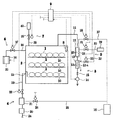
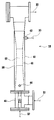
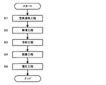
以下、この発明を実施した解凍装置の具体的実施例を図面に基づいて詳細に説明する。図1は、実施例の概略構成の説明図であり、図2は、同実施例の要部の説明である。図3には、同実施例の制御手順を示すフローチャート図である。 Hereinafter, specific examples of the decompression apparatus embodying the present invention will be described in detail with reference to the drawings. FIG. 1 is an explanatory diagram of a schematic configuration of the embodiment, and FIG. 2 is an explanation of a main part of the embodiment. FIG. 3 is a flowchart showing the control procedure of the embodiment.
この実施例の解凍装置は、業務用解凍装置に適用されるものである。この解凍装置は、被処理物としての被解凍物1を収容する処理室としての解凍室2と、前記解凍室2内の空気を吸引排気して減圧状態にする減圧手段3と、前記解凍室2内へ蒸気を供給する蒸気供給(給蒸)手段4と、前記減圧手段3の構成要素を冷却する冷却手段5と、前記解凍室2内へエタノール蒸気を供給するエタノール蒸気供給手段6と、減圧状態の前記解凍室2内に外気を導入することにより復圧する復圧手段7と、前記解凍室2内の圧力を検出する圧力検出器8と、前記圧力検出器8の信号を入力してメモリに記憶した制御手順に基づき前記解凍室2内の低圧蒸気による被解凍物1の解凍を制御する制御手段9とを主要部として備えている。
The thawing device of this embodiment is applied to a business thawing device. The thawing apparatus includes a thawing chamber 2 as a processing chamber for storing an object to be thawed 1 as an object to be processed, a decompression means 3 that sucks and exhausts the air in the thawing chamber 2 to reduce the pressure, and the thawing chamber. Steam supply means 4 for supplying steam into the steam 2, cooling means 5 for cooling the components of the decompression means 3, ethanol steam supply means 6 for supplying ethanol steam into the thawing chamber 2, A decompression means 7 for restoring pressure by introducing outside air into the decompression chamber 2 in a decompressed state, a
被解凍物1は、真空(パック)包装した肉類などであり、真空包装していないものも含まれる。真空包装した被解凍物1は、解凍前に刃物などにより包装に切り込みや孔からなる通気孔(図示省略)を形成することが望ましい。こうした通気孔の形成により、低圧蒸気解凍時に包装が膨らむことによる熱伝達の阻害を防止できるとともに、蒸気が直接食材に触れることにより、解凍時間を短縮することができる。
The to-
前記解凍室2は、被解凍物1を出し入れするための扉(図示省略)を備えている。また、前記解凍室2内には、被解凍物1を収容するための棚10,10,…が設けられている。図1で示した前記棚10は、三段に設けた構成としている。
The thawing chamber 2 is provided with a door (not shown) for taking in and out the
前記減圧手段3は、前記解凍室2内を減圧して、空気を排除するものであり、減圧路1
1とこの減圧路11に設ける減圧器とを含む。そして、この減圧器は、蒸気エゼクタ12と、熱交換器13と、水封式の真空ポンプ14とから構成される。さらに、前記減圧路11には、前記解凍室2方向への流れを阻止する逆止弁15を備えている。
The decompression means 3 decompresses the inside of the thawing chamber 2 to exclude air.
1 and a decompressor provided in the
前記蒸気エゼクタ12には、一次蒸気ボイラ16からの蒸気を供給する第一給蒸路17が接続され、この第一給蒸路17に第一給蒸弁18を備える。
The
前記熱交換器13は、高温の流体から低温の流体に熱を伝える冷却機能を有するもので、シェル・アンド・チューブ型の熱交換器としており、シェル13aと、チューブ13bとにより形成される。
The
前記給蒸手段4は、一端を前記解凍室2に接続し、清浄蒸気を前記解凍室2内へ供給するための第二給蒸路19を含む。この第二給蒸路19には、軟水器20と、この軟水器20から供給される軟水を用いて清浄蒸気を生成する蒸気発生源としての二次蒸気ボイラ21と、蒸気の供給を制御する第二給蒸弁22と、前記解凍室2内へ蒸気を噴出するための蒸気噴出口23とを備えている。前記第二給蒸弁22は、開度を調節することにより給蒸量を調節可能な比例弁などの弁を用いる。
The steam supply means 4 includes a second
前記軟水器20は、原水供給路24から供給される原水をイオン交換により軟水化する装置である。
The
前記二次蒸気ボイラ21は、前記一次蒸気ボイラ16を間接加熱源とする二次蒸気ボイラ(リボイラと称することができる。)であり、前記一次蒸気ボイラ16と第三給蒸路25により接続されている。この第三給蒸路25には、第三給蒸弁26を備えている。
The
前記二次蒸気ボイラ21は、ステンレス製とし、前記軟水器20の軟水を用いるとともに無薬注としている。これにより、前記解凍室2への供給蒸気は、薬品や鉄分を含まないので、安全な低圧蒸気による解凍が実現される。
The
前記冷却手段5は、前記蒸気エゼクタ12のエゼクタ部27に形成される冷却部28と、前記熱交換器13のシェル13aと、冷水器29とにより構成される。この冷却部28には、前記冷水器29からの冷水を供給する第一冷水路30が接続され、この第一冷水路30には、第一冷水弁31を備えている。そして、前記シェル13aは、前記第一冷水路30から分岐させた第二冷水路32を接続し、チューブ13bは、前記減圧路11と接続している。この第二冷水路32には、第二冷水弁33を備えている。
The cooling means 5 includes a cooling
また、前記第一冷水路30の出口は、前記第二冷水路32の前記熱交換器13と前記第二冷水弁33との間に接続され、前記冷却部28から出た冷水を前記シェル13a内へ導入し、前記熱交換器13のチューブ13bを間接冷却するように構成されている。
The outlet of the first
前記エタノール蒸気供給手段6は、一端を前記解凍室2に接続し、エタノール蒸気を前記解凍室2内へ供給するためのエタノール蒸気供給路34を含む。前記エタノール蒸気供給手段6には、前記エタノール蒸気供給路34の他端に、エタノール液を貯留するエタノール貯留容器35と、このエタノール貯留容器35の外側を加熱してエタノール蒸気を生成させるためのヒータ36とを備えている。このエタノール蒸気供給路34には、エタノール蒸気供給弁37を備えている。このエタノール蒸気供給弁37は、開度を調節することによりエタノール蒸気供給量を調節可能な比例弁などの弁を用いる。
The ethanol vapor supply means 6 includes an ethanol
また、前記復圧手段7は、一端を前記解凍室2に接続した外気導入路としての復圧路38を含む。そして、この復圧路38には、外気導入の制御用の復圧弁39と、除菌用のフ
ィルタ40とを備える。前記復圧弁39は、開度を調整することにより導入空気量を調整可能なモータバルブなどの比例弁を用いる。
Further, the return pressure means 7 includes a
ここで、前記減圧手段3の構成要素である前記蒸気エゼクタ12の前記冷却部28の構成を詳細に説明する。図2を参照して、前記蒸気エゼクタ12において、前記エゼクタ部(ジャケット形成部)27の第一外壁41を包囲するように前記冷却部28の第二外壁42を図示の如く形成し、この第一外壁41と第二外壁42との間を冷水流通路として形成している。43,44は、それぞれ蒸気入口,蒸気出口である。また、45は、蒸気噴射部である。この蒸気噴射部45において前記第一給蒸路17からの蒸気を噴射させると、エゼクタ効果により前記解凍室2内の空気や蒸気が前記減圧路11を通して吸引され、排気される。
Here, the configuration of the cooling
前記制御手段9は、前記圧力検出器8からの信号を入力し、所定の処理手順(プログラム)に従い、前記各給蒸弁18,22,26,前記真空ポンプ14,前記各冷水弁31,33,前記ヒータ36,前記エタノール蒸気供給弁37,前記復圧弁39などを制御するように構成されている。
The control means 9 inputs a signal from the
以下、この実施例の処理手順の全体的な流れを図3にしたがい説明する。前記制御手段9は、次の工程を順次実行する。処理工程としては、前記解凍室2内の空気を排除する空気排除工程(ステップS1),蒸気を供給して被解凍物1を解凍する解凍工程(ステップS2),前記蒸気エゼクタ12および前記熱交換器13を冷却する冷却工程(ステップS3),エタノール蒸気を供給して被解凍物1,前記蒸気エゼクタ12および前記熱交換器13を殺菌する殺菌工程(ステップS4),前記解凍室2内を大気圧に戻す復圧工程(ステップS5)に分けられる。
Hereinafter, the overall flow of the processing procedure of this embodiment will be described with reference to FIG. The control means 9 sequentially executes the following steps. The processing steps include an air removal step (step S1) for removing air in the thawing chamber 2, a thawing step (step S2) for supplying steam to defrost the
各工程についての動作の説明をする。まず、被解凍物1を前記解凍室2に収容する。被解凍物1が真空包装されている場合は、刃物などにより包装に切り込みを入れて通気孔(図示省略)を形成してから、被解凍物1を前記解凍室2内に収容する。そして、扉(図示省略)を閉めた後、運転スイッチ(図示省略)をオンにし、前記空気排除工程(ステップS1)を開始する。
The operation of each process will be described. First, the
この空気排除工程(ステップS1)では、まず、前記制御手段9は、水封式の前記真空ポンプ14を作動させて所定の圧力まで減圧した後、前記第一給蒸弁18を開いて前記蒸気エゼクタ12へ蒸気を供給し、前記蒸気エゼクタ12を作動させる。これにより、前記解凍室2内の空気が前記減圧路11を通って外気へ流出される。そして、前記解凍室2内の圧力が設定値に達すると、前記真空ポンプ14を停止させるとともに、前記第一給蒸弁18を閉じ、この空気排除工程(ステップS1)を終了する。
In this air exhausting step (step S1), first, the control means 9 operates the water-sealed
つぎに、前記解凍工程(ステップS2)では、前記制御手段9が、前記解凍室2内の前記圧力検出器8による検出圧力が設定圧力(約23.4hPa)となるように前記減圧手段3および前記給蒸手段4を制御することで、被解凍物1の解凍が行われる。この解凍工程(ステップS2)では、前記減圧手段3を作動させ、かつ前記第二給蒸弁22の開度を調整して前記蒸気噴射口23から飽和蒸気を前記解凍室2内へ連続的に蒸気供給しながら、前記解凍室2内を大気圧以下の所定低圧に保持して解凍を行う。
Next, in the thawing step (step S2), the control means 9 uses the
図1を参照して具体的に説明すると、前記制御手段9は、前記給蒸手段4の作動時に前記第三給蒸弁26を開き、前記二次蒸気ボイラ21を運転状態とし、所定圧の蒸気を供給可能な状態とする。そして、前記制御手段9は、前記第二給蒸弁22の開度を調節して、前記圧力検出器8による検出圧力が前記設定圧力となるように制御する。前記二次蒸気ボイラ21への軟水の供給制御は、水位制御器(図示省略)の検出信号により、前記給水ポ
ンプ(図示省略)および前記軟水供給弁(図示省略)を制御することにより行われる。前記一次蒸気ボイラ16は、自ら制御手段(図示省略)により、所定圧の蒸気を発生するように制御される。
Specifically, referring to FIG. 1, the control means 9 opens the third
そして、設定の解凍時間が経過すると、前記制御手段9は、解凍終了条件が満たされたと判断して、前記解凍工程(ステップS2)を終了する。 When the set thawing time elapses, the control means 9 determines that the thawing end condition is satisfied, and ends the thawing process (step S2).
つぎに、前記冷却工程(ステップS3)について説明する。前記制御手段9は、前記第一冷水弁31および前記第二冷水弁33を開いて、前記冷水器29から前記冷却部28および前記シェル13aへ冷水を供給して、前記蒸気エゼクタ12および前記熱交換器13を冷却する。このとき、前記第一給蒸弁18および前記第三給蒸弁26は、前記蒸気エゼクタ12および前記給蒸手段4を作動させないように、閉止されている。
Next, the cooling step (step S3) will be described. The control means 9 opens the first
また、前記冷却部28を出た冷水は、前記第二冷水路32に入って前記冷水器29からの冷水と合流して、前記熱交換器13の前記シェル13a内に導かれる。そして、この熱交換器13の前記チューブ13bが間接的に冷却される。この冷却工程(ステップS3)は、前記殺菌工程(ステップS4)が終了するまで、継続して行われる。
Further, the cold water that has exited the
つぎに、前記殺菌工程(ステップS4)について説明する。この殺菌工程(ステップS4)は、前記制御手段9が、前記減圧手段3,前記冷却手段5および前記エタノール蒸気供給手段6を制御して被解凍物1の殺菌を行う第一殺菌と、前記蒸気エゼクタ12および前記熱交換器13の殺菌を行う第二殺菌とを同時に行う工程である。
Next, the sterilization step (step S4) will be described. In this sterilization step (step S4), the control means 9 controls the decompression means 3, the cooling means 5 and the ethanol vapor supply means 6 to sterilize the
この殺菌工程(ステップS4)において、前記制御手段9は、前記蒸気エゼクタ12および前記熱交換器13を作動させず、前記真空ポンプ14のみを作動させる制御を行う。これは、前記減圧手段3が低圧状態を維持し、かつ高温にならないために行われる。
In this sterilization step (step S4), the control means 9 performs control to operate only the
まず、前記第一殺菌について図1にしたがい説明する。前記制御手段9は、前記エタノール蒸気供給手段6を作動させ、前記ヒータ36にてエタノール液が入った前記エタノール貯留容器35を加熱することより、エタノール蒸気を生成する。そして、前記制御手段9は、前記エタノール蒸気供給弁37を開いて、エタノール蒸気を前記解凍室2内へ供給する。そして、前記制御手段9は、前記エタノール蒸気供給弁37の開度を調整し、エタノール蒸気を前記解凍室2内へ連続的に供給しながら、前記解凍室2内を大気圧以下の所定圧力に保持して被解凍物1の殺菌を行う。
First, the first sterilization will be described with reference to FIG. The control means 9 operates the ethanol vapor supply means 6 and heats the
そして、前記制御手段9は、設定時間経過すると前記エタノール蒸気供給弁37を閉じ、供給を停止するとともに前記ヒータ36への通電を停止する制御を行う。この設定時間は、前記解凍室2に収容される被解凍物1の総表面面積に応じて、変更するように構成する。
When the set time elapses, the control means 9 closes the ethanol vapor supply valve 37 to stop supply and stop energization of the
低圧下の前記解凍室2内へ供給されるエタノール蒸気は、前記解凍室内2の低温部に集中的に凝縮をするため、低温である解凍状態の被解凍物1に凝縮をする。これにより、被解凍物1は、前記解凍室2から確実に殺菌された状態で被解凍物1を取り出すことができ、長期にわたって衛生的に保つことができる。
The ethanol vapor supplied into the thawing chamber 2 under low pressure concentrates in the low temperature part of the thawing chamber 2 and therefore condenses into the
また、前記解凍工程(ステップS2)時、前記給蒸手段4にて供給された蒸気は、前記解凍室2の内壁に水として付着している。この水は、前記減圧手段3が作動して減圧処理を行うため、水は蒸発し、蒸発潜熱によって前記解凍室2の内壁温度を低下させる。これにより、前記殺菌工程(ステップS4)では、被解凍物1だけではなく、前記解凍室2の内壁にもエタノール蒸気が凝縮し、前記解凍室2内を被解凍物1と同様に殺菌することが
できる。
Further, during the thawing step (step S2), the steam supplied by the steam supply means 4 adheres to the inner wall of the thawing chamber 2 as water. Since this water is decompressed by the decompression means 3 being operated, the water evaporates, and the inner wall temperature of the thawing chamber 2 is lowered by the latent heat of vaporization. Thereby, in the said sterilization process (step S4), ethanol vapor | steam condenses not only to the to-
つぎに、前記第二殺菌について説明する。前記制御手段9は、前記冷却工程(ステップS3)を継続する制御を行っている。そのため、前記蒸気エゼクタ12は、前記冷却部28内を流通する冷水により、前記熱交換器13は、前記シェル13a内を流通する冷水によって、それぞれ間接冷却され、温度が低下した状態にある。この状態において、エタノール蒸気は、前記真空ポンプ14が作動していることで、前記減圧路11を流れる。このエタノール蒸気は、低温状態を維持している前記蒸気エゼクタ12および前記熱交換器13に凝縮される。こうして、手の届かない前記蒸気エゼクタ12と前記熱交換器13は、殺菌作用のあるエタノール蒸気の凝縮によって殺菌されるため、水蒸気で殺菌を行うよりも殺菌効果を高くすることができる。
Next, the second sterilization will be described. The control means 9 performs control to continue the cooling process (step S3). Therefore, the
エタノール蒸気の供給設定時間(第一設定時間)が経過すると、前記制御手段9は、前記真空ポンプ14を停止し、前記エタノール蒸気供給弁37を閉じ、第二設定時間この状態を保持させる制御を行う。この状態保持は、被解凍物1の殺菌効果を高めるために行われる。第二設定時間経過後、前記制御手段9は、前記殺菌工程(ステップS4)を終了する。
When the ethanol vapor supply set time (first set time) elapses, the control means 9 stops the
そして、前記制御手段9は、前記復圧工程(ステップS5)へ移行する。この復圧工程(ステップS5)では、前記制御手段9が、前記復圧弁39の開度を調整しながら開いて外気導入を開始する。前記解凍室2内が大気圧まで復圧された後、前記扉(図示省略)を開いて前記解凍室2内から被解凍物1を取り出して、一連の処理を完了する。
And the said control means 9 transfers to the said pressure recovery process (step S5). In the return pressure step (step S5), the control means 9 opens while adjusting the opening of the
1 被解凍物(被処理物)
2 解凍室(処理室)
3 減圧手段
5 冷却手段
6 エタノール蒸気供給手段
9 制御手段
1 Object to be thawed (processed object)
2 Thawing room (processing room)
3 Depressurization means 5 Cooling means 6 Ethanol vapor supply means 9 Control means
Claims (1)
A processing chamber 2 that accommodates the workpiece 1, a decompression means 3 in the processing chamber 2, a cooling means 5 that cools components of the decompression means 3, and an ethanol vapor supply means 6 into the processing chamber 2 And a control means 9 for controlling the decompression means 3, the cooling means 5 and the ethanol vapor supply means 6. The control means 9 controls the cooling means 5 to cool the components of the decompression means 3. And a sterilization step of controlling the decompression means 3, the cooling means 5 and the ethanol vapor supply means 6 to sterilize the decompression means 3 with ethanol vapor.
Priority Applications (1)
| Application Number | Priority Date | Filing Date | Title |
|---|---|---|---|
| JP2004121032A JP2005295961A (en) | 2004-04-16 | 2004-04-16 | Food machinery |
Applications Claiming Priority (1)
| Application Number | Priority Date | Filing Date | Title |
|---|---|---|---|
| JP2004121032A JP2005295961A (en) | 2004-04-16 | 2004-04-16 | Food machinery |
Publications (1)
| Publication Number | Publication Date |
|---|---|
| JP2005295961A true JP2005295961A (en) | 2005-10-27 |
Family
ID=35328254
Family Applications (1)
| Application Number | Title | Priority Date | Filing Date |
|---|---|---|---|
| JP2004121032A Pending JP2005295961A (en) | 2004-04-16 | 2004-04-16 | Food machinery |
Country Status (1)
| Country | Link |
|---|---|
| JP (1) | JP2005295961A (en) |
Cited By (3)
| Publication number | Priority date | Publication date | Assignee | Title |
|---|---|---|---|---|
| JP2008096029A (en) * | 2006-10-12 | 2008-04-24 | Miura Co Ltd | Composite cooling device and composite cooling method |
| JP2011145021A (en) * | 2010-01-15 | 2011-07-28 | Tlv Co Ltd | Waste steam recovery device |
| JP2020156628A (en) * | 2019-03-26 | 2020-10-01 | 三浦工業株式会社 | Food machinery and its sterilization method |
-
2004
- 2004-04-16 JP JP2004121032A patent/JP2005295961A/en active Pending
Cited By (4)
| Publication number | Priority date | Publication date | Assignee | Title |
|---|---|---|---|---|
| JP2008096029A (en) * | 2006-10-12 | 2008-04-24 | Miura Co Ltd | Composite cooling device and composite cooling method |
| JP2011145021A (en) * | 2010-01-15 | 2011-07-28 | Tlv Co Ltd | Waste steam recovery device |
| JP2020156628A (en) * | 2019-03-26 | 2020-10-01 | 三浦工業株式会社 | Food machinery and its sterilization method |
| JP7229463B2 (en) | 2019-03-26 | 2023-02-28 | 三浦工業株式会社 | Food machine and its sterilization method |
Similar Documents
| Publication | Publication Date | Title |
|---|---|---|
| JP5251557B2 (en) | Cooling device and cooling method | |
| JP4924147B2 (en) | Food machine with vacuum cooling function and its operation method | |
| JP5370859B2 (en) | Food machinery | |
| WO2013114539A1 (en) | Steam sterilization device | |
| US20190015534A1 (en) | Sterilized-liquefied gas producing apparatus | |
| JP6283926B2 (en) | Sterilizer | |
| JP6226129B2 (en) | Sterilizer | |
| JP2018064878A (en) | Steam sterilizer and operating method thereof | |
| JP2005080788A (en) | Vacuum steamer | |
| JP2005295961A (en) | Food machinery | |
| JP5907424B2 (en) | Sterilizer | |
| JP2005278577A (en) | Thawing apparatus | |
| JP2005224209A (en) | Thawing method and apparatus therefor | |
| JP4867647B2 (en) | Saturated steam heater | |
| JP2021058122A (en) | Sterilizer | |
| KR100665714B1 (en) | Temperature equalizer in steam sterilizer chamber | |
| JP2005249286A (en) | Food machine | |
| JP6036274B2 (en) | Sterilizer | |
| JP6909443B2 (en) | Sterilizer | |
| JP2005046088A (en) | Vacuum steam thawing machine | |
| JP4640701B2 (en) | Vacuum cooling device | |
| JP5930392B2 (en) | Sterilizer | |
| JP2005245397A (en) | Steam-heating apparatus | |
| JP2006346149A (en) | Cooking apparatus | |
| JPWO2013114539A1 (en) | Steam sterilizer |
Legal Events
| Date | Code | Title | Description |
|---|---|---|---|
| A621 | Written request for application examination |
Free format text: JAPANESE INTERMEDIATE CODE: A621 Effective date: 20061020 |
|
| A977 | Report on retrieval |
Free format text: JAPANESE INTERMEDIATE CODE: A971007 Effective date: 20081031 |
|
| A131 | Notification of reasons for refusal |
Free format text: JAPANESE INTERMEDIATE CODE: A131 Effective date: 20090721 |
|
| A02 | Decision of refusal |
Free format text: JAPANESE INTERMEDIATE CODE: A02 Effective date: 20091207 |