JP2005296027A - Endoscope light source device - Google Patents
Endoscope light source device Download PDFInfo
- Publication number
- JP2005296027A JP2005296027A JP2004111842A JP2004111842A JP2005296027A JP 2005296027 A JP2005296027 A JP 2005296027A JP 2004111842 A JP2004111842 A JP 2004111842A JP 2004111842 A JP2004111842 A JP 2004111842A JP 2005296027 A JP2005296027 A JP 2005296027A
- Authority
- JP
- Japan
- Prior art keywords
- light
- light source
- period
- source device
- rotating plate
- Prior art date
- Legal status (The legal status is an assumption and is not a legal conclusion. Google has not performed a legal analysis and makes no representation as to the accuracy of the status listed.)
- Granted
Links
Images
Landscapes
- Instruments For Viewing The Inside Of Hollow Bodies (AREA)
- Endoscopes (AREA)
- Closed-Circuit Television Systems (AREA)
- Studio Devices (AREA)
Abstract
【課題】 動画レートを低下させることなく、静止画像の解像度を向上させるように、照明光の照射制御が可能な内視鏡用光源装置を実現する。
【解決手段】
第2の光L2は、トリガー信号S1により、電荷読出し期間TR中の偶数フィールド期間T3においては被写体に照射されず、その間CCDは露光されない。また、トリガー信号S1により、電荷の読出し方法を、1フィールド期間ごとに全画像信号を読出すフィールド読出しから、1フレーム期間T1で全画像信号を読出すフレーム読出しに変更する。この結果、電荷読出し期間TRの奇数フィールド期間T2と偶数フィールド期間T3とにおいて、奇数及び偶数ラインにより生成された電荷がそれぞれ読出され、解像度の高い静止画像が形成される。また、フレーム読出しは、電荷読出し期間TRにおける静止画像の形成にのみ用いられるため、動画レートの低下によるちらつきを生じさせない。
【選択図】 図4
PROBLEM TO BE SOLVED: To realize an endoscope light source device capable of controlling illumination light irradiation so as to improve the resolution of a still image without reducing the moving image rate.
[Solution]
The second light L2 is not irradiated on the subject in the even field period T3 in the charge reading period TR by the trigger signal S1, and the CCD is not exposed during that time. In addition, the trigger signal S1 changes the charge reading method from field reading in which all image signals are read out every field period to frame reading in which all image signals are read out in one frame period T1. As a result, in the odd-numbered field period T2 and the even-numbered field period T3 of the charge reading period TR, the charges generated by the odd-numbered and even-numbered lines are read out, and a still image with high resolution is formed. Further, since the frame reading is used only for forming a still image in the charge reading period TR, flickering due to a decrease in the moving image rate is not caused.
[Selection] Figure 4
Description
本発明は、内視鏡用光源装置に関し、特に、被写体像の解像度を向上させるための照射光の照射制御が可能な電子内視鏡用光源装置に関する。 The present invention relates to an endoscope light source device, and more particularly, to an electronic endoscope light source device capable of controlling irradiation light irradiation to improve the resolution of a subject image.
電子内視鏡装置は、一般に、被写体である体内組織を照明するための光源等を備えたプロセッサと、撮像素子を備えたビデオスコープにより構成される。光源からの照明光は、ライトガイドを介して、ビデオスコープから被写体に照射される。そして、撮像素子によって得られた映像信号がプロセッサに送信され、プロセッサにおいて映像信号に所定の処理が施されることにより、被写体像がモニタに表示される。 An electronic endoscope apparatus is generally composed of a processor including a light source for illuminating a body tissue that is a subject, and a video scope including an image sensor. Illumination light from the light source is applied to the subject from the video scope via the light guide. Then, the video signal obtained by the image sensor is transmitted to the processor, and a predetermined process is performed on the video signal in the processor, whereby the subject image is displayed on the monitor.
電子内視鏡装置に使用される撮像素子として、インターライン型CCDが広く用いられている。そして、一般に、色差順次方式によって撮像されて撮像素子に蓄積された電荷を2ライン分づつ加算して読み出す、いわゆるフィールド読出し(画素混合読出し)により、動画像が形成される。 An interline CCD is widely used as an image sensor used in an electronic endoscope apparatus. Then, generally, a moving image is formed by so-called field reading (pixel mixture reading), in which charges that are imaged by the color difference sequential method and accumulated in the image sensor are added and read out by two lines.
一方、静止画像を形成するために、インターライン型CCDに蓄積された電荷を読出す方法として、読出しのための遮光期間を設けた上で、撮像素子の奇数ラインと偶数ラインの信号電荷を、1フィールド期間ずつ順次読出して1フレーム期間で全電荷の読出しを終了する、いわゆるフレーム読出し(全画素読出し)が知られている(例えば特許文献1参照)。このフレーム読出しにより、フィールド読出しよりも高い解像度の静止画像が実現されている。撮像素子の奇数ラインと偶数ラインの信号電荷を、1フィールド期間ずつ順次読出して1フレーム期間で全電荷の読出しを終了する、いわゆるフレーム読出し(全画素読出し)が知られている(例えば特許文献1参照)。
モータ制御による絞りでは、応答時間が長いため、フレーム読出しに必要とされる1フィールド期間に対応する遮光期間を設けることは不可能である。また、最新の液晶素子を用いても、フレーム読出しに必要とされる短時間の遮光時間は実現できない。 In the diaphragm controlled by the motor, since the response time is long, it is impossible to provide a light shielding period corresponding to one field period required for frame reading. Further, even if the latest liquid crystal element is used, a short light shielding time required for frame reading cannot be realized.
一方、回転板等の遮光手段を用いることにより、フレーム読出しを可能にする短い遮光時間が実現できる。しかしながら、この場合、全電荷の読出しに要する時間がフレーム期間であって、フィールド読出しよりも長いことから、動画レートが低下し、動画像を表示する際にフレーム残像によるちらつきを生じ易い。 On the other hand, by using a light shielding means such as a rotating plate, a short light shielding time enabling frame reading can be realized. However, in this case, since the time required to read out all charges is a frame period, which is longer than that in field readout, the moving image rate is lowered, and flickering due to frame afterimage is likely to occur when displaying a moving image.
本発明は、汎用的な遮光手段を用いつつ、動画レートを低下させることなく、静止画像の解像度を向上させるように、照明光の照射制御が可能な内視鏡用光源装置を実現することを目的とする。 The present invention realizes an endoscope light source device capable of controlling illumination light illumination so as to improve the resolution of a still image without reducing the moving image rate while using a general-purpose light shielding means. Objective.
本発明の光源装置は、インターライン型の撮像素子を備え、撮像素子に蓄積された垂直方向の2ライン分の電荷を加算して読み出すことにより動画像を形成する電子内視鏡装置に用いられる光源装置である。光源装置は、被写体を照明するための照明光を放射する光源と、光源により放射された照明光を2つの光である第1の光と第2の光とに分ける照明光分割手段と、第1の光と第2の光とを、1フレーム期間周期で交互に通過および遮光させる照射制御手段と、第2の光のみを遮光可能な遮光手段とを備える。そして、静止画像形成のためのユーザによるフリーズ動作の直後の1フレーム期間である電荷読出し期間において、撮像素子の同一露光時に得られた全電荷を撮像素子の奇数ライン及び偶数ラインごとに読出すことを可能にするために、光源装置の遮光手段は、フリーズ動作に従い、電荷読出し期間における少なくとも1フィールド期間、第2の光を遮光する。 The light source device of the present invention is used in an electronic endoscope device that includes an interline type imaging device and forms a moving image by adding and reading out charges for two vertical lines accumulated in the imaging device. It is a light source device. The light source device includes: a light source that emits illumination light for illuminating a subject; an illumination light splitting unit that divides the illumination light emitted by the light source into two lights, a first light and a second light; Irradiation control means for alternately passing and shielding one light and the second light in a cycle of one frame period, and a light shielding means capable of shielding only the second light. Then, in the charge reading period, which is one frame period immediately after the freeze operation by the user for forming a still image, all charges obtained during the same exposure of the image sensor are read for each odd line and even line of the image sensor. Therefore, the light shielding unit of the light source device shields the second light in accordance with the freeze operation for at least one field period in the charge readout period.
照射制御手段は、例えば、第1の光および第2の光を通過させる通過部と遮光する遮光部とを有する回転板と、回転板を駆動する回転板駆動手段とから成る。この場合、回転板駆動手段が、回転板が1フレーム期間で1回転するように、回転板を制御することが好ましい。また、遮光部の大きさにより、第1の光と第2の光とを遮光する時間を調整可能であることが望ましい。 The irradiation control means includes, for example, a rotating plate having a passage portion that allows the first light and the second light to pass therethrough and a light shielding portion that shields light, and a rotating plate driving means that drives the rotating plate. In this case, it is preferable that the rotating plate driving means controls the rotating plate so that the rotating plate makes one rotation in one frame period. In addition, it is desirable that the time for blocking the first light and the second light can be adjusted depending on the size of the light blocking portion.
遮光手段は、例えば、遮光用液晶である。 The light shielding means is, for example, a light shielding liquid crystal.
光源装置は、第1の光と第2の光との光路を調整する光路調整手段を有することが好ましく、光路調整手段は、例えば、ミラーを含む。 The light source device preferably includes an optical path adjusting unit that adjusts an optical path between the first light and the second light, and the optical path adjusting unit includes, for example, a mirror.
照明光分割手段は、例えば、偏光ビームスピリッタである。 The illumination light splitting means is, for example, a polarization beam spiriter.
本発明の電子内視鏡装置は、インターライン型の撮像素子を備え、撮像素子に蓄積された垂直方向の2ライン分の電荷を加算して読み出すことにより動画像を形成する。電子内視鏡装置は、被写体を照明するための照明光を放射する光源と、光源により放射された照明光を2つの光である第1の光と第2の光とに分ける照明光分割手段と、第1の光と第2の光とを、1フレーム期間周期で交互に通過および遮光させる照射制御手段と、第2の光のみを遮光可能な遮光手段と、静止画像形成のためのユーザによるフリーズ動作を検知するフリーズ動作検知手段とを備える。そして、フリーズ動作検知手段がフリーズ動作を検知すると、フリーズ動作の直後の1フレーム期間である電荷読出し期間において、撮像素子の同一露光時に得られた全電荷を撮像素子の奇数ライン及び偶数ラインごとに読出すことを可能にするために、遮光手段が、フリーズ動作に従い、電荷読出し期間における少なくとも1フィールド期間、第2の光を遮光する。 The electronic endoscope apparatus of the present invention includes an interline type image pickup device, and forms a moving image by adding and reading out charges for two lines in the vertical direction accumulated in the image pickup device. An electronic endoscope apparatus includes a light source that emits illumination light for illuminating a subject, and an illumination light splitting unit that divides the illumination light emitted by the light source into two lights, a first light and a second light Irradiating control means for alternately passing and shielding the first light and the second light in a cycle of one frame period, a shielding means capable of shielding only the second light, and a user for forming a still image And freeze operation detecting means for detecting the freeze operation by. Then, when the freeze operation detecting means detects the freeze operation, in the charge readout period, which is one frame period immediately after the freeze operation, all charges obtained during the same exposure of the image sensor are obtained for each odd line and even line of the image sensor. In order to enable reading, the light blocking means blocks the second light in accordance with the freeze operation for at least one field period in the charge reading period.
本発明によれば、汎用的な遮光手段を用いつつ、動画レートを低下させることなく、静止画像の解像度を向上させるように、照明光の照射制御が可能な内視鏡用光源装置を実現できる。 ADVANTAGE OF THE INVENTION According to this invention, the light source device for endoscopes which can perform illumination light irradiation control so that the resolution of a still image can be improved, without reducing a moving image rate, using a general-purpose light-shielding means is realizable. .
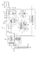
以下、本発明の実施形態を、図面を参照して説明する。図1は、本実施形態における電子内視鏡装置10のブロック図である。
Embodiments of the present invention will be described below with reference to the drawings. FIG. 1 is a block diagram of an
電子内視鏡装置10は、患者の体腔内の撮影に用いられるビデオスコープ20と、ビデオスコープ20に照明光を供給するとともにビデオスコープ20から送られてくる画像信号を処理するプロセッサ30とを備える。ビデオスコープ20は、プロセッサ30に着脱自在に接続され、プロセッサ30にはモニタ60が接続されている。
The
プロセッサ30には、照明光を照射する光源装置31が設けられている。光源装置31は、光源32、第1及び第2偏光ビームスピリッタ33、34、遮光用液晶35、回転板36等を備える。光源点灯スイッチ(図示せず)が操作されて電源供給されると、光源32は、被写体を照明するための照明光を放射する。放射された照明光は、後述のように、第1及び第2偏光ビームスピリッタ33、34、遮光用液晶35を介して回転板36に到達する。回転板36は、モータ37によって駆動され、照明光を一定時間ずつ遮光、通過させる。回転板36を通過した照明光は、光路制御部38によって光路が調整された後、調光絞り45に入射する。調光絞り45によって光量が調整された照明光は、導光レンズ40を介してライトガイド12の入射端12Aに入射する。ライトガイド12は、照明光を観察部位のあるビデオスコープ20の先端部へ伝達し、ライトガイド12を通った照明光は出射端12Bから観察部位に出射される。
The
被写体である観察部位で反射した照明光は、対物レンズ(図示せず)、カラーフィルタ(図示せず)を通ってインターライン型のCCD22の受光面に到達し、これにより被写体像がCCD22の受光面に形成される。CCD22では、カラーフィルタを通る色に応じた被写体像の画像信号が光電変換により発生する。ここではカラーテレビジョン方式としてNTSC方式が適用されており、CCD22の奇数ラインと偶数ラインによって生成された画像信号を加算することにより、1フィールド期間、すなわち1/60秒間隔ごとに、CCD22の同一露光時に得られた全ての画素信号が順次読み出され、初期信号処理回路24へ送られる。
Illumination light reflected from the observation site, which is a subject, passes through an objective lens (not shown) and a color filter (not shown) and reaches the light receiving surface of the
ビデオスコープ20内には、ビデオスコープ20全体を制御するスコープ制御部26と、ビデオスコープ20の特性や信号処理に関するデータがあらかじめ記憶されたEEPROM28が設けられている。スコープ制御部26は、初期信号処理回路24に対して制御信号を送るとともに、適宜EEPROM28からデータを読み出す。例えば、ビデオスコープ20がプロセッサ30に接続されると、スコープ制御部26は、CCD22のフレームレート情報をEEPROM28から読出し、初期信号処理回路24に送る。初期信号処理回路24は、CCD22のフレームレート情報を、プロセッサ30側のシステムコントロール回路44内の調光制御部41に送る。調光制御部41は、受信したCCD22のフレームレート情報に基づいた1フレーム期間で回転板36を1回転させるように、モータ37を制御する。
In the
また、初期信号処理回路24では、読み出された画像信号に増幅処理が施され、さらにアナログ信号からデジタル信号に変換される。そして、ホワイトバランス調整など様々な処理がデジタル画像信号に対して施され、輝度信号Y、色差信号Cb、Crが生成される。輝度信号Yおよび色差信号Cb、Crは、プロセッサ30のプロセッサ信号処理回路48へ送られ、NTSC信号などの映像信号に変換され、モニタ60へ出力される。これにより、被写体像がモニタ60にリアルタイムで表示される。
In the initial
ビデオスコープ20には、フリーズボタン25が設けられている。ユーザが、フリーズボタン25を押下すると、静止画像を形成するためのトリガー信号が、スコープ制御部26を介して調光制御部41に送信される。調光制御部41は、受信した信号に基づき、遮光用液晶35をオフ状態にするための信号を遮光用液晶35に送信する。この結果、遮光用液晶35がオン状態からオフ状態に切換えられた後に、後述のように、静止画像が表示される。
The
調光制御部41、CPU42を含むシステムコントロール回路44は、プロセッサ30全体を制御し、光源装置31、調光絞り45、タイミングコントロール回路46などに制御信号を出力する。また、システムコントロール回路44内のROM43には、プロセッサ30の制御に関するプログラムが格納されている。タイミングコントロール回路46からは、信号処理タイミングを調整するクロックパルスがプロセッサ30内の各回路に出力され、また、映像信号に付加される同期信号がプロセッサ信号処理回路48に送られる。
A
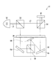
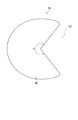
図2は、光源装置31を示す図である。図3は、回転板36を示す図である
FIG. 2 is a diagram showing the
光源32から放射される照明光の光路上には、第1偏光ビームスピリッタ33が設けられている。第1偏光ビームスピリッタ33に入射した照明光は、そのP波成分のみが、第1の光L1として第1偏光ビームスピリッタ33によって反射され、回転板36に到達する。一方、照明光のS波成分は、第2の光L2として、第1偏光ビームスピリッタ33を通過して第2偏光ビームスピリッタ34に入射する。第2偏光ビームスピリッタ34に入射した第2の光L2は、反射により遮光用液晶35に達する。遮光用液晶35が、調光制御部41の制御によりオン状態の時、第2の光L2は、遮光用液晶35によって反射されて回転板36に入射し、遮光用液晶35がオフ状態の時は、遮光用液晶35内を透過して、回転板36に向かうことはない。
On the optical path of the illumination light emitted from the
モータ37によって駆動される回転板36は、第1の光L1及び第2の光L2を、一定時間ずつ交互に遮光、および通過させる。回転板36の表面は、扇形であり、第1の光L1及び第2の光L2を遮光する遮光面50を有する(図3参照)。第1の光L1及び第2の光L2は、回転板36の通過領域52が光路上にある時のみ、回転板36を通過する。回転板36は、1フレーム期間、すなわち1/30秒ごとに1回転するため、第1の光L1と第2の光L2の遮光、及び通過を交互にそれぞれ一定時間ずつ、1フレーム期間周期で反復する。回転板36を通過した第1の光L1及び第2の光L2は、いずれも光路制御部38に入射する。なお、遮光面50の中心角αを調整し、遮光面50の大きさを変更することにより、1フレーム期間中に被写体に照射される照明光(第1の光L1及び第2の光L2)の照射時間を調整することができ、被写体に照射する照明光の光量調整が可能である。
The rotating
光路制御部38は、第1〜第3反射ミラー54〜56、ハーフプリズム58を備える。第1の光L1は、回転板36を通過すると、第1反射ミラー54によって反射され、ハーフプリズム58に入射する。さらに、第1の光L1は、ハーフプリズム58によって反射されて光路を変え、調光絞り45に向けて光路制御部38から出射する。一方、第2の光L2は、回転板36の通過後、第2及び第3反射ミラー55、56によって反射され、ハーフプリズム58に入射する。第2の光L2は、ハーフプリズム58によって光路変更されず、その結果、第1の光L1と第2の光L2とは、ハーフプリズム58を出射すると同一の光路を進む。なお、第1の光L1は、奇数フィールド時のCCD22の露光に用いられ、第2の光L2は、偶数フィールド時の露光に用いられる。
The optical path control
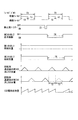
図4は、照明光の照射を示すタイミングチャートである。 FIG. 4 is a timing chart showing illumination light irradiation.
先述のように、フレーム期間T1は1/30秒であり、1/60秒ずつの奇数フィールド期間T2と偶数フィールド期間T3の2つのフィールド期間から成る。フリーズボタン25が押下され、静止画像を表示するためのトリガー信号S1が、調光制御部41に送信されると、遮光用液晶35は、トリガー信号S1の直後のフレーム期間である電荷読出し期間TRに渡って、オフ状態になるように制御される。遮光用液晶35のオフ状態の開始は、調光制御部41によるトリガー信号S1直後の奇数フィールド期間T2の開始時に同期される。この結果、第2の光L2は、フレーム期間T1において遮光用液晶35により遮光されるため、回転板36に入射する第1の光L1の照射光量が一定であるのに対し、第2の光L2は、フレーム期間T1中は回転板36に照射されない。
As described above, the frame period T1 is 1/30 second, and is composed of two field periods of an odd field period T2 and an even field period T3 of 1/60 seconds. When the
このため、回転板36通過後の第1の光L1が、奇数フィールド期間T2ごとにCCD22の露光に用いられ、フレーム期間T1を周期として光量変化が一定であるのに対し、第2の光L2は、電荷読出し期間TRに含まれる偶数フィールド期間T3においては、被写体に照射されず、この間CCD22は露光されない。
For this reason, the first light L1 after passing through the
なお、スコープ制御部26がトリガー信号S1を受信すると、スコープ制御部26は、初期信号処理回路24を介して指示信号をCCD22に送信することにより、画像信号の読出し方法を一時的に変換する。すなわち、1フィールド期間ごとに1フレーム分の画像信号を読出すフィールド読出しから、1フレーム期間TR1で1フレーム分の画像信号を読出すフレーム読出しに変更する。フレーム読出しの開始は、トリガー信号S1直後の奇数フィールド期間T2の開始時、すなわち電荷読出し期間TRの開始時に同期される。
When the
このように、偶数フィールド期間T3においてCCD22が露光されず、電荷読出し方式がフレーム読出しに変更されたことから、CCD22の奇数ラインによって生成された電荷のみが読出され、偶数フィールド期間T3においては、偶数ラインにより生成された電荷が読出される。こうしてラインごとに読出された全電荷に基づき、プロセッサ信号処理回路48において、静止画像を表示するための映像信号が生成される。この映像信号により、静止画像がモニタ60上に表示される。さらに、静止画像の映像信号は、システムコンロール回路44内のメモリ(図示せず)に記録されるため、ユーザの印刷開始動作により、プリンタ(図示せず)は静止画像を印刷する。
As described above, since the
フレーム読出しにより、奇数ラインと偶数ラインの電荷が加算されずに読出されることから、フィールド読出しによる場合よりも解像度の高い静止画像が形成される。また、フレーム読出しは、1フレーム期間TRにおける静止画像の形成にのみ用いられ、形成された静止画像の表示以外における動画像表示のための動画像の形成には、フィールド読出しが用いられる。このため、フレーム読出しを用いることによる動画レートの低下を招かず、ユーザにちらつきを感知させない。 By reading the frame, the charges of the odd and even lines are read without being added, so that a still image with higher resolution than that by the field reading is formed. Frame reading is used only for forming a still image in one frame period TR, and field reading is used for forming a moving image for displaying a moving image other than displaying the formed still image. For this reason, the moving image rate is not lowered by using the frame reading, and the user is not perceived to flicker.
以上のように、本実施形態によれば、汎用的な遮光手段である遮光用液晶35と回転板36等を用いて、動画レートを低下させずにちらつきを防止しつつ解像度の高い静止画像を形成するように、照明光の照射制御が可能な内視鏡用光源装置を実現できる。さらに、照明光の光路を二つに分けることにより応答速度に余裕ができるため、光源装置を構成する部品の選定の幅が広くなる。
As described above, according to the present embodiment, a still image with high resolution can be obtained while preventing flicker without reducing the moving image rate by using the light shielding
照射制御手段及び遮光手段の構成は、回転板36及びこれを駆動するモータ37、遮光
用液晶35に限定されず、例えば遮光板及びこれを第1の光L1・第2の光L2の各光路に適宜挿脱するように駆動するVCMであっても良い。この場合、ビデオスコープ20のフリーズボタン25の押下が行われると、直後の第1の光L1によるCCD22の露光タイミングから静止画モードに入る訳であるが、その前の第2の光L2による通常露光動作終了と共に、VCMにより遮光板を制御して第2の光L2を遮光し、静止画モードが完了したら、VCMによる第2の光L2の遮光を解除するようにすることにより、本来VCMの動作に要求される高度な性能を必要とせずに動作させることができる。
The configurations of the irradiation control means and the light shielding means are not limited to the
光路制御手段の各ミラーの配置等は、本実施形態に限定されない。例えば、ハーフプリズム58を除き、第3反射ミラー56としてDMD(デジタルマイクロミラーデバイス)を用いて、第1反射ミラー54からの第1の光L1と、第2反射ミラー55からの第2の光L2のいずれもが、第3反射ミラー56によって光路調整されても良い。
The arrangement of the mirrors of the optical path control means is not limited to this embodiment. For example, the first light L1 from the
10 電子内視鏡装置
20 ビデオスコープ
22 CCD(撮像素子)
25 フリーズボタン(フリーズ動作検知手段)
26 スコープ制御部(フリーズ動作検知手段)
30 プロセッサ
31 光源装置
32 光源
33 第1偏光ビームスピリッタ(照明光分割手段)
34 第2偏光ビームスピリッタ(照明光分割手段)
35 遮光用液晶(遮光手段)
36 回転板(照射制御手段)
37 モータ(回転板駆動手段・照射制御手段)
38 光路制御部(光路調整手段)
41 調光制御部
50 遮光面(遮光部)
52 通過領域(通過部)
54〜56 第1〜第3反射ミラー(光路調整手段・ミラー)
58 ハーフプリズム(光路調整手段)
L1 第1の光
L2 第2の光
TR 電荷読出し期間
10
25 Freeze button (freeze motion detection means)
26 Scope control unit (freeze motion detection means)
30
34 Second polarized beam splitter (illumination beam splitting means)
35 Light-shielding liquid crystal (light-shielding means)
36 Rotating plate (irradiation control means)
37 Motor (rotary plate drive means / irradiation control means)
38 Optical path controller (optical path adjustment means)
41
52 Passing area (passing part)
54-56 1st-3rd reflective mirror (optical path adjusting means / mirror)
58 Half prism (light path adjustment means)
L1 First light L2 Second light TR Charge readout period
Claims (8)
被写体を照明するための照明光を放射する光源と、
前記光源により照射された前記照明光を2つの光である第1の光と第2の光とに分ける照明光分割手段と、
前記第1の光と前記第2の光とを、1フレーム期間周期で交互に通過および遮光させる照射制御手段と、
前記第2の光のみを遮光可能な遮光手段とを備え、
静止画像形成のためのユーザによるフリーズ動作の直後の1フレーム期間である電荷読出し期間において、前記撮像素子の同一露光時に得られた全電荷を前記撮像素子の奇数ライン及び偶数ラインごとに読出すことを可能にするために、
前記遮光手段が、前記フリーズ動作に従い、前記電荷読出し期間における少なくとも1フィールド期間、前記第2の光を遮光することを特徴とする光源装置。 A light source device used in an electronic endoscope device that includes an interline type imaging device and forms a moving image by adding and reading out charges for two vertical lines accumulated in the imaging device,
A light source that emits illumination light to illuminate the subject;
Illumination light dividing means for dividing the illumination light irradiated by the light source into two lights, a first light and a second light;
Irradiation control means for alternately passing and blocking the first light and the second light at a cycle of one frame period;
A light shielding means capable of shielding only the second light,
In a charge readout period, which is one frame period immediately after a freeze operation by a user for forming a still image, all charges obtained during the same exposure of the image sensor are read for each odd line and even line of the image sensor. To enable
The light source device, wherein the light shielding unit shields the second light in accordance with the freeze operation for at least one field period in the charge reading period.
被写体を照明するための照明光を放射する光源と、
前記光源により照射された前記照明光を2つの光である第1の光と第2の光とに分ける照明光分割手段と、
前記第1の光と前記第2の光とを、1フレーム期間周期で交互に通過および遮光させる照射制御手段と、
前記第2の光のみを遮光可能な遮光手段と、
静止画像形成のためのユーザによるフリーズ動作を検知するフリーズ動作検知手段とを備え、
前記フリーズ動作検知手段が前記フリーズ動作を検知すると、前記フリーズ動作の直後の1フレーム期間である電荷読出し期間において、前記撮像素子の同一露光時に得られた全電荷を前記撮像素子の奇数ライン及び偶数ラインごとに読出すことを可能にするために、
前記遮光手段が、前記フリーズ動作に従い、前記電荷読出し期間における少なくとも1フィールド期間、前記第2の光を遮光することを特徴とする電子内視鏡装置。
An electronic endoscope apparatus that includes an interline type image sensor and forms a moving image by adding and reading out charges for two vertical lines accumulated in the image sensor,
A light source that emits illumination light to illuminate the subject;
Illumination light dividing means for dividing the illumination light irradiated by the light source into two lights, a first light and a second light;
Irradiation control means for alternately passing and blocking the first light and the second light at a cycle of one frame period;
A light shielding means capable of shielding only the second light;
A freeze operation detecting means for detecting a freeze operation by a user for forming a still image,
When the freeze operation detecting means detects the freeze operation, in the charge reading period, which is one frame period immediately after the freeze operation, all charges obtained during the same exposure of the image sensor are converted into odd lines and even lines of the image sensor. In order to be able to read line by line,
The electronic endoscope apparatus, wherein the light shielding means shields the second light in accordance with the freeze operation for at least one field period in the charge reading period.
Priority Applications (1)
| Application Number | Priority Date | Filing Date | Title |
|---|---|---|---|
| JP2004111842A JP4531432B2 (en) | 2004-04-06 | 2004-04-06 | Endoscope light source device |
Applications Claiming Priority (1)
| Application Number | Priority Date | Filing Date | Title |
|---|---|---|---|
| JP2004111842A JP4531432B2 (en) | 2004-04-06 | 2004-04-06 | Endoscope light source device |
Publications (2)
| Publication Number | Publication Date |
|---|---|
| JP2005296027A true JP2005296027A (en) | 2005-10-27 |
| JP4531432B2 JP4531432B2 (en) | 2010-08-25 |
Family
ID=35328311
Family Applications (1)
| Application Number | Title | Priority Date | Filing Date |
|---|---|---|---|
| JP2004111842A Expired - Fee Related JP4531432B2 (en) | 2004-04-06 | 2004-04-06 | Endoscope light source device |
Country Status (1)
| Country | Link |
|---|---|
| JP (1) | JP4531432B2 (en) |
Cited By (1)
| Publication number | Priority date | Publication date | Assignee | Title |
|---|---|---|---|---|
| WO2018062561A1 (en) * | 2016-09-29 | 2018-04-05 | 株式会社ニコン | Image-capturing element and camera |
Citations (8)
| Publication number | Priority date | Publication date | Assignee | Title |
|---|---|---|---|---|
| JPH0990244A (en) * | 1995-09-19 | 1997-04-04 | Fuji Photo Optical Co Ltd | Electronic endoscope device |
| JPH10304284A (en) * | 1997-04-24 | 1998-11-13 | Nikon Corp | LCD projector |
| JPH10328129A (en) * | 1997-06-02 | 1998-12-15 | Olympus Optical Co Ltd | Fluorescent observing device |
| JPH11276432A (en) * | 1998-03-30 | 1999-10-12 | Fuji Photo Optical Co Ltd | Electronic endoscope device for setting the light-shielding period |
| JP2001224015A (en) * | 2000-02-07 | 2001-08-17 | Olympus Optical Co Ltd | Endoscope system and light source device |
| JP2001275961A (en) * | 2000-01-25 | 2001-10-09 | Olympus Optical Co Ltd | Endoscopic instrument |
| JP3370871B2 (en) * | 1996-10-23 | 2003-01-27 | 富士写真光機株式会社 | Electronic endoscope device |
| JP2003190091A (en) * | 2001-12-26 | 2003-07-08 | Pentax Corp | Illumination probe for fluorescence observation, electronic endoscope system, and electronic endoscope |
-
2004
- 2004-04-06 JP JP2004111842A patent/JP4531432B2/en not_active Expired - Fee Related
Patent Citations (8)
| Publication number | Priority date | Publication date | Assignee | Title |
|---|---|---|---|---|
| JPH0990244A (en) * | 1995-09-19 | 1997-04-04 | Fuji Photo Optical Co Ltd | Electronic endoscope device |
| JP3370871B2 (en) * | 1996-10-23 | 2003-01-27 | 富士写真光機株式会社 | Electronic endoscope device |
| JPH10304284A (en) * | 1997-04-24 | 1998-11-13 | Nikon Corp | LCD projector |
| JPH10328129A (en) * | 1997-06-02 | 1998-12-15 | Olympus Optical Co Ltd | Fluorescent observing device |
| JPH11276432A (en) * | 1998-03-30 | 1999-10-12 | Fuji Photo Optical Co Ltd | Electronic endoscope device for setting the light-shielding period |
| JP2001275961A (en) * | 2000-01-25 | 2001-10-09 | Olympus Optical Co Ltd | Endoscopic instrument |
| JP2001224015A (en) * | 2000-02-07 | 2001-08-17 | Olympus Optical Co Ltd | Endoscope system and light source device |
| JP2003190091A (en) * | 2001-12-26 | 2003-07-08 | Pentax Corp | Illumination probe for fluorescence observation, electronic endoscope system, and electronic endoscope |
Cited By (1)
| Publication number | Priority date | Publication date | Assignee | Title |
|---|---|---|---|---|
| WO2018062561A1 (en) * | 2016-09-29 | 2018-04-05 | 株式会社ニコン | Image-capturing element and camera |
Also Published As
| Publication number | Publication date |
|---|---|
| JP4531432B2 (en) | 2010-08-25 |
Similar Documents
| Publication | Publication Date | Title |
|---|---|---|
| US8094206B2 (en) | Endoscope processor executing gamma correction on image signals using gamma coefficients | |
| JP4786915B2 (en) | Electronic endoscope device | |
| CN103347433B (en) | medical equipment | |
| US20070147810A1 (en) | Electronic endoscope with brightness adjustment function | |
| JP4745790B2 (en) | Electronic endoscope device | |
| JP2971554B2 (en) | Laser scanning retinal camera | |
| JPWO2013121616A1 (en) | Endoscope device | |
| JPS6076717A (en) | Endoscope device | |
| JP2001224015A (en) | Endoscope system and light source device | |
| JPH10118019A (en) | Light source unit for endoscope and electronic endoscope apparatus | |
| JP4827398B2 (en) | Electronic endoscope apparatus provided with light shielding member | |
| US7905598B2 (en) | Ophthalmologic photographing apparatus | |
| JP4531432B2 (en) | Endoscope light source device | |
| JP2016123576A (en) | Fluorescent observation apparatus | |
| JP5763893B2 (en) | Image processing system and program, and operation method of endoscope system | |
| JP4495560B2 (en) | Endoscope light source device | |
| JP2020137614A (en) | Electronic endoscopy system | |
| JP2000296114A (en) | Eye photographing device | |
| JPS62201411A (en) | Endoscope device | |
| JP3905696B2 (en) | 3D image input device | |
| JP2001211448A (en) | Endoscope system | |
| JP4439245B2 (en) | Electronic endoscope device | |
| JP5006545B2 (en) | Light source device | |
| JP2633784B2 (en) | Electronic endoscope device | |
| JP4953759B2 (en) | Electronic endoscope device |
Legal Events
| Date | Code | Title | Description |
|---|---|---|---|
| A621 | Written request for application examination |
Free format text: JAPANESE INTERMEDIATE CODE: A621 Effective date: 20070315 |
|
| A711 | Notification of change in applicant |
Free format text: JAPANESE INTERMEDIATE CODE: A712 Effective date: 20080501 |
|
| A977 | Report on retrieval |
Free format text: JAPANESE INTERMEDIATE CODE: A971007 Effective date: 20100402 |
|
| TRDD | Decision of grant or rejection written | ||
| A01 | Written decision to grant a patent or to grant a registration (utility model) |
Free format text: JAPANESE INTERMEDIATE CODE: A01 Effective date: 20100525 |
|
| A01 | Written decision to grant a patent or to grant a registration (utility model) |
Free format text: JAPANESE INTERMEDIATE CODE: A01 |
|
| A61 | First payment of annual fees (during grant procedure) |
Free format text: JAPANESE INTERMEDIATE CODE: A61 Effective date: 20100609 |
|
| R150 | Certificate of patent or registration of utility model |
Free format text: JAPANESE INTERMEDIATE CODE: R150 |
|
| FPAY | Renewal fee payment (event date is renewal date of database) |
Free format text: PAYMENT UNTIL: 20130618 Year of fee payment: 3 |
|
| FPAY | Renewal fee payment (event date is renewal date of database) |
Free format text: PAYMENT UNTIL: 20130618 Year of fee payment: 3 |
|
| FPAY | Renewal fee payment (event date is renewal date of database) |
Free format text: PAYMENT UNTIL: 20140618 Year of fee payment: 4 |
|
| R250 | Receipt of annual fees |
Free format text: JAPANESE INTERMEDIATE CODE: R250 |
|
| S531 | Written request for registration of change of domicile |
Free format text: JAPANESE INTERMEDIATE CODE: R313531 |
|
| R350 | Written notification of registration of transfer |
Free format text: JAPANESE INTERMEDIATE CODE: R350 |
|
| R250 | Receipt of annual fees |
Free format text: JAPANESE INTERMEDIATE CODE: R250 |
|
| LAPS | Cancellation because of no payment of annual fees |