JP2005296094A - dishwasher - Google Patents
dishwasher Download PDFInfo
- Publication number
- JP2005296094A JP2005296094A JP2004112957A JP2004112957A JP2005296094A JP 2005296094 A JP2005296094 A JP 2005296094A JP 2004112957 A JP2004112957 A JP 2004112957A JP 2004112957 A JP2004112957 A JP 2004112957A JP 2005296094 A JP2005296094 A JP 2005296094A
- Authority
- JP
- Japan
- Prior art keywords
- cleaning
- pump
- water
- motor
- impeller
- Prior art date
- Legal status (The legal status is an assumption and is not a legal conclusion. Google has not performed a legal analysis and makes no representation as to the accuracy of the status listed.)
- Pending
Links
Images
Landscapes
- Washing And Drying Of Tableware (AREA)
Abstract
Description
本発明は、食器の洗浄を行う食器洗い機に関するものである。 The present invention relates to a dishwasher for washing dishes.
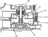
従来、この種の食器洗い機の洗浄ポンプは、例えば、図5に示すような構成が考えられていた。すなわち、ポンプ21は、洗浄ノズル(図示せず)から洗浄水を噴射する第1のインペラ22を有した第1のケーシング23と、機外に洗浄水を排出する第2のインペラ24を有した第2のケーシング25を備え、前記第1のインペラ22と第2のインペラ24を同軸とし、上下方向に配設してモータ26により回転駆動する。そして、第1のケーシング23と第2のケーシング25の間に洗浄水案内部27を設けたものである(例えば、特許文献1参照)。
しかしながら、上記の構成によれば、洗浄ポンプ21は強力な洗浄力が得られる遠心ポンプで構成するのが一般的であり、第1のケーシング23の下方に洗浄水案内部27を設けて、洗浄水を下方から吸込む構成としている。加えて、洗浄ポンプの下方に設けた洗浄水案内部27の下方にさらに排水ポンプを構成したものであることから、モータ26を含めたポンプ全体の高さが高くなり、洗浄槽の下方に設置した場合に食器洗い機の本体を小型化することができないという問題があった。
However, according to the above-described configuration, the
そして、洗浄と排水を1つのポンプで構成することも考えられているが、上記のように洗浄ポンプは強力な洗浄力を得るために遠心ポンプで構成する必要があることから、ポンプの下方に洗浄水案内部を設けなければならず、薄型化には限界があった。 It is also considered that the cleaning and drainage are configured with a single pump. However, as described above, the cleaning pump needs to be configured with a centrifugal pump in order to obtain a strong cleaning power. A washing water guide must be provided, and there was a limit to reducing the thickness.
本発明は、上記の課題を解決するもので、洗浄ポンプの高さを低くし、食器洗い機の本体形状を大型化することなく多量の食器が洗浄できるようにすることを目的としている。 An object of the present invention is to solve the above-described problems, and an object of the present invention is to reduce the height of a washing pump so that a large amount of dishes can be washed without increasing the shape of the main body of the dishwasher.
上記の目的を達成するために、本発明の食器洗い機は、排水ポンプの機能を備えた洗浄ポンプのインペラの回転軸と、モータの回転軸を同心として略鉛直方向に構成するとともに、吸込み経路をモータと洗浄ポンプの間に配設したものである。 In order to achieve the above object, the dishwasher of the present invention is configured in a substantially vertical direction with the rotation shaft of the impeller of the washing pump having the function of a drainage pump and the rotation shaft of the motor being concentric, and a suction path is provided. It is disposed between the motor and the cleaning pump.
これにより、ポンプの高さを低くすることができ、本体形状を大型化することなく洗浄槽の容積を拡大して、洗浄可能な食器の量を多くすることができ、コンパクトな本体形状で多量の食器を洗浄することができる。 As a result, the height of the pump can be reduced, the volume of the washing tank can be increased without increasing the size of the main body, and the amount of tableware that can be cleaned can be increased. The dishes can be washed.
本発明の食器洗い機は、本体形状を大型化することなく洗浄槽の容積を拡大して、洗浄可能な食器の量を多くすることができ、コンパクトな本体形状で多量の食器を洗浄することができる。 The dishwasher of the present invention can expand the volume of the washing tank without increasing the size of the main body, increase the amount of tableware that can be washed, and can wash a large amount of tableware with a compact main body shape. it can.
第1の発明は、貯水部を有した洗浄槽と、前記貯水部の洗浄水を加圧する洗浄ポンプと、前記洗浄ポンプによって加圧された洗浄水を前記洗浄槽内に噴射する洗浄ノズルと、前記洗浄ポンプを駆動するモータとを具備し、前記洗浄ポンプは遠心式とし、インペラの回転軸と前記モータの回転軸を同心として略鉛直方向に構成するとともに、前記洗浄ポンプの吸込み経路を前記洗浄ポンプとモータとの間に設けたことにより、ポンプの高さを低くすることができ、本体形状を大型化することなく洗浄槽の容積を拡大して、収容可能な食器の量を多くすることができるとともに、コンパクトな本体形状で多量の食器を洗浄することができる。また、洗浄槽を所定の容積に設定した場合は、本体の小型化を促進することができるようになり、狭い場所への設置性を向上することができる。 The first invention includes a cleaning tank having a water storage unit, a cleaning pump that pressurizes cleaning water in the water storage unit, a cleaning nozzle that injects cleaning water pressurized by the cleaning pump into the cleaning tank, A motor that drives the cleaning pump, the cleaning pump is a centrifugal type, and the rotating shaft of the impeller and the rotating shaft of the motor are concentric and configured in a substantially vertical direction, and the suction path of the cleaning pump is cleaned By providing it between the pump and the motor, the height of the pump can be reduced, the volume of the washing tank can be increased without increasing the size of the main body, and the amount of tableware that can be accommodated is increased. A large amount of tableware can be washed with a compact body shape. In addition, when the cleaning tank is set to a predetermined volume, it is possible to promote downsizing of the main body, and it is possible to improve the installation property in a narrow place.
第2の発明は、吸込み経路を、洗浄ポンプを駆動するモータの回転軸のシール部を囲むように構成したことにより、シール部を吸込み経路内に収容することができ、モータを含めたポンプの高さを低くでき、薄型化を促進することができる。 In the second aspect of the invention, the suction path is configured to surround the seal part of the rotating shaft of the motor that drives the cleaning pump, so that the seal part can be accommodated in the suction path. The height can be lowered and the thinning can be promoted.
第3の発明は、洗浄ポンプをモータの下方に配設するとともに、前記洗浄ポンプの吸込み口を同洗浄ポンプの上部に設けたことにより、吸込み経路に流動する洗浄水を引き込む必要がなく、確実かつ容易にポンプ内へ流動させることができる。 In the third aspect of the invention, the cleaning pump is disposed below the motor, and the suction port of the cleaning pump is provided in the upper part of the cleaning pump, so that it is not necessary to draw in the cleaning water flowing into the suction path. And it can easily flow into the pump.
第4の発明は、吸込み口をシール部より径大としたことにより、洗浄水が吸込み経路から洗浄ポンプ内へ入る際の抵抗を少なくして、容易に流動させることができる。 In the fourth aspect of the present invention, since the suction port has a diameter larger than that of the seal portion, the resistance when the cleaning water enters the cleaning pump from the suction path can be reduced and can flow easily.
第5の発明は、吸込み口を、吸込み経路からインペラの内側に洗浄水を供給する構成としたことにより、インペラの回転によるポンプ能力を高めて洗浄水を効率よく吐出することができ、洗浄効果を高めることができるとともに、短時間で排出することができる。 In the fifth aspect of the invention, the suction port is configured to supply cleaning water from the suction path to the inside of the impeller, so that the pumping ability by the rotation of the impeller can be increased and the cleaning water can be discharged efficiently, and the cleaning effect And can be discharged in a short time.
第6の発明は、吸込み経路を構成する蓋体を有し、前記蓋体にシール部を設けたことにより、モータとポンプを簡略な構成で一体に設けることができる。 According to the sixth aspect of the present invention, the motor and the pump can be integrally provided with a simple configuration by including the lid that constitutes the suction path and providing the seal on the lid.
第7の発明は、洗浄ポンプは、インペラを正逆反転可能とし、正転時に洗浄水を洗浄ノズルへ吐出して洗浄を行う第1の吐出口と、反転時に洗浄水を吐出して排水を行う第2の吐出口を設けたことにより、1つのモータと1つのポンプで洗浄と排水を行うことができ、構成の簡略化と薄型化を促進することができる。 According to a seventh aspect of the invention, the cleaning pump is configured so that the impeller can be reversed forward and reverse, and the first discharge port that performs cleaning by discharging cleaning water to the cleaning nozzle at the time of normal rotation and the cleaning water by discharging the cleaning water at the time of reverse rotation By providing the second discharge port, cleaning and draining can be performed with one motor and one pump, and simplification and thinning of the configuration can be promoted.
第8の発明は、第1の吐出口と第2の吐出口は、少なくとも一方の中心をインペラの高さ範囲内に位置するように設定したことにより、インペラの回転によるポンプ能力を高めて洗浄水を効率よく吐出することができ、洗浄効果を高めることができるとともに、短時間で排出することができる。 According to an eighth aspect of the present invention, the first discharge port and the second discharge port are set so that at least one center is positioned within the height range of the impeller, thereby improving the pumping ability by the rotation of the impeller and cleaning. Water can be discharged efficiently, the cleaning effect can be enhanced, and the water can be discharged in a short time.
以下、本発明の実施の形態について、図面を参照しながら説明する。なお、本実施の形態によって本発明が限定されるものではない。 Hereinafter, embodiments of the present invention will be described with reference to the drawings. Note that the present invention is not limited to the present embodiment.
(実施の形態1)
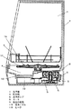
図1〜図3において、1は食器洗い機の本体2内に形成した洗浄槽で、洗浄を行う食器をセットする食器かご3を取り出し可能に設置する。洗浄槽1の底部には水を貯める貯水部4を設けている。洗浄槽1への給水は、水道水の止水あるいは給水を行う給水弁(図示せず)を設けた給水経路(図示せず)を介して行われ、供給される水を所定の水位に保つ水位センサ(図示せず)、および制御回路等からなる貯水量制御手段(図示せず)により行われる。
(Embodiment 1)
1 to 3, reference numeral 1 denotes a washing tank formed in the main body 2 of the dishwasher, which is installed so as to be able to take out a tableware basket 3 for setting tableware to be washed. A water storage section 4 for storing water is provided at the bottom of the cleaning tank 1. Water is supplied to the washing tank 1 through a water supply path (not shown) provided with a water supply valve (not shown) for stopping or supplying tap water, and the supplied water is kept at a predetermined water level. This is performed by a water storage amount control means (not shown) including a water level sensor (not shown) and a control circuit.
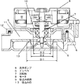
5は貯水部4に貯水された水を加圧する洗浄ポンプで、この洗浄ポンプ5内のインペラ6の回転軸7と、洗浄ポンプ5の駆動源であるモータ8の回転軸7を同心として略鉛直方向に構成し、洗浄ポンプ5をモータ8の下方に配設している。9は洗浄ポンプ5内に洗浄水を流入させる吸込み経路で、洗浄ポンプ5とこの洗浄ポンプ5を駆動するモータ8との間に設けてあり、インペラ6の回転軸7を取り囲むように中心付近に形成している。
A
10はモータ8の回転軸7をシールするシール部で、洗浄ポンプ5のインペラ6とモータ8との間に設けており、吸込み経路9内に突出させることにより同吸込み経路9で囲むように構成している。11は吸込み経路9を構成する蓋体で、パッキン12を介して水密に固着しており、上記シール部10はこの蓋体11に設けている。
13は洗浄ポンプ5のインペラ6の上部に設けた吸込み口で、シール部10の直径D3より大なる直径D2の孔を開けてあり、洗浄水が吸込み経路9から洗浄ポンプ5内へ入る際の抵抗を少なくして、容易に流動させることができるようになっている。そして、この吸込み口13の直径D2は、インペラ6の内側に洗浄水を供給するように、インペラ6の直径D1より径小にしている。
洗浄ポンプ5は、インペラ6を正逆反転可能な遠心式とし、正転時は第1の吐出口14から洗浄水を吐出して洗浄ノズル15へ供給し、噴射口16から洗浄槽1内に噴射する。洗浄ノズル15は水平方向に回転可能に設けてあり、噴射口16から洗浄水を噴射する際の反力で回転し、洗浄槽1内の広い範囲に噴射できるようにしている。反転時は第2の吐出口17から機外へ洗浄水を吐出して排水を行う。
The
18は貯水部4に貯水された水を加熱するヒータで、乾燥時は送風手段(図示せず)により洗浄槽1内に供給される送風を加熱する。19は食器に付着していた残菜を補足するフィルタである。
次に、上記実施の形態における動作について説明する。まず、貯水量制御手段(図示せず)により水道水が洗浄槽1の内部へ給水され、洗浄槽1の底部に設けられた貯水部4に貯まり、所定の水位になったところで給水を停止する。次に、洗浄ポンプ5が正転動作し、貯水部2の洗浄水は洗浄ポンプ5により加圧され、吸込み経路9を通りインペラ6の上部に設けた吸込み口13から洗浄ポンプ5内へ入り、第1の吐出口14から洗浄水を吐出して洗浄ノズル15へ供給し、噴射口16から洗浄槽1内の食器かご3に置かれた食器に向けて噴射され洗浄を行う。
Next, the operation in the above embodiment will be described. First, tap water is supplied to the inside of the washing tank 1 by a water storage amount control means (not shown), stored in the water storage section 4 provided at the bottom of the washing tank 1, and stopped at a predetermined water level. . Next, the
食器の汚れを落とした洗浄水は再び貯水部2へ戻る。洗浄水はヒータ18によって加熱され、予め設定されている適度な高温となって洗浄力が高められるとともに、洗浄を行った洗浄水の汚染物はフィルタ19により捕捉され、再び洗浄ポンプ5へと循環して洗浄を行う際に汚染物の再付着を抑える。所定の洗浄が終了すると洗浄ポンプ5を反転動作し、第2の吐出口17から機外へ洗浄水を吐出して排水を行う。
The wash water from which the dishes have been cleaned returns to the water storage unit 2 again. The washing water is heated by the
以上のように本実施の形態によれば、排水ポンプの機能を備えた洗浄ポンプ5のインペラ6の回転軸7と、モータ8の回転軸7を同心として略鉛直方向に構成するとともに、吸込み経路9をモータ8と洗浄ポンプ5の間に配設したことにより、モータ8と洗浄ポンプ5の間に形成される空間を吸込み経路9として有効に利用することができるようになり、モータ8の上端部からポンプ5の下端部までの全体の高さを低くすることができ、貯水部4の側方に形成される洗浄槽1の下方の空間Sにコンパクト収容することができる。したがって、本体形状を大型化することなく洗浄槽1の容積を拡大して、洗浄可能な食器の量を多くすることができる他、洗浄可能な食器の量を少なくすることなく本体形状を小型化することができる。
As described above, according to the present embodiment, the rotation shaft 7 of the impeller 6 of the
また、洗浄ポンプ5の吸込み口13を、シール部10より径大としたことにより、筒状のシール部10の下端が吸込み口13に近接する場合でも、吸込み経路9から洗浄ポンプ5内へ洗浄水をスムーズに流入させることができ、その流動を容易にすることができる。そして、シール部10の直径D3と、吸込み口13の直径D2と、インペラ6の直径D1の関係は、D1>D2>D3に設定している。なお、吸込み口13は、必ずしも図2のような回転軸7を中心とした1つの孔である必要はなく、回転軸7から離れた位置に複数の孔を設けて構成することもできる。
In addition, since the
(実施の形態2)
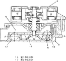
図4は、実施の形態2の洗浄ポンプおよびモータの拡大断面図を示したもので、洗浄ポンプ5は、インペラ6を正逆反転可能とし、正転時に洗浄水を洗浄ノズル15へ吐出して洗浄を行う第1の吐出口14と、反転時に洗浄水を吐出して機外へ排水を行う第2の吐出口17を設けている。上記第1の吐出口14と第2の吐出口17は、少なくとも一方の中心Aをインペラ6の高さ範囲B内に位置するように設定している。
(Embodiment 2)
FIG. 4 shows an enlarged cross-sectional view of the cleaning pump and motor of the second embodiment. The
この構成によれば、1つのモータと1つのポンプで洗浄と排水を行うことができ、構成の簡略化と薄型化を促進することができるとともに、インペラ6の回転によるポンプ能力を高めて洗浄水を効率よく吐出することができる。したがって、洗浄時には食器等の洗浄効果を高めることができるとともに、排水時には排出時間を短縮することができる。 According to this configuration, cleaning and draining can be performed with one motor and one pump, and the simplification and thinning of the configuration can be promoted. Can be discharged efficiently. Accordingly, it is possible to enhance the cleaning effect of tableware and the like during cleaning, and it is possible to shorten the discharge time during drainage.
なお、上記実施の形態1で記載した各構成、ならびに実施の形態2は必ずしも一体で構成する必要はなく、独自に実施することができる。 Each configuration described in the first embodiment and the second embodiment are not necessarily configured integrally, and can be implemented independently.
以上のように、本発明にかかる食器洗い機は、本体形状を大型化することなく洗浄槽の容積を拡大して、洗浄可能な食器の量を多くすることができるので、コンパクトな本体形状で多量の食器を洗浄できる食器洗い機として有用である。 As described above, the dishwasher according to the present invention can enlarge the volume of the washing tank without increasing the size of the main body and increase the amount of tableware that can be washed. It is useful as a dishwasher that can wash dishes.
1 洗浄槽
4 貯水部
5 洗浄ポンプ
6 インペラ
7 回転軸
8 モータ
9 吸込み経路
10 シール部
13 吸込み口
15 洗浄ノズル
DESCRIPTION OF SYMBOLS 1 Washing tank 4
Claims (8)
Priority Applications (1)
| Application Number | Priority Date | Filing Date | Title |
|---|---|---|---|
| JP2004112957A JP2005296094A (en) | 2004-04-07 | 2004-04-07 | dishwasher |
Applications Claiming Priority (1)
| Application Number | Priority Date | Filing Date | Title |
|---|---|---|---|
| JP2004112957A JP2005296094A (en) | 2004-04-07 | 2004-04-07 | dishwasher |
Publications (1)
| Publication Number | Publication Date |
|---|---|
| JP2005296094A true JP2005296094A (en) | 2005-10-27 |
Family
ID=35328373
Family Applications (1)
| Application Number | Title | Priority Date | Filing Date |
|---|---|---|---|
| JP2004112957A Pending JP2005296094A (en) | 2004-04-07 | 2004-04-07 | dishwasher |
Country Status (1)
| Country | Link |
|---|---|
| JP (1) | JP2005296094A (en) |
Citations (2)
| Publication number | Priority date | Publication date | Assignee | Title |
|---|---|---|---|---|
| JPS62117298U (en) * | 1986-01-17 | 1987-07-25 | ||
| JPH1043120A (en) * | 1996-08-01 | 1998-02-17 | Zojirushi Corp | Pump for dishwasher |
-
2004
- 2004-04-07 JP JP2004112957A patent/JP2005296094A/en active Pending
Patent Citations (2)
| Publication number | Priority date | Publication date | Assignee | Title |
|---|---|---|---|---|
| JPS62117298U (en) * | 1986-01-17 | 1987-07-25 | ||
| JPH1043120A (en) * | 1996-08-01 | 1998-02-17 | Zojirushi Corp | Pump for dishwasher |
Similar Documents
| Publication | Publication Date | Title |
|---|---|---|
| JP6407290B2 (en) | Sink type washing machine | |
| CN101406382B (en) | Machine for cleaning dishware | |
| KR102695818B1 (en) | dish Washer | |
| JP2005296094A (en) | dishwasher | |
| JP2008167961A (en) | dishwasher | |
| JP2008167960A (en) | dishwasher | |
| JP2010264160A (en) | dishwasher | |
| KR20230040717A (en) | A Nano bubble dishwasher | |
| JP4400318B2 (en) | Pump and dishwasher with this pump | |
| JP2004060620A (en) | Reversible pump and dishwasher | |
| JP3661390B2 (en) | dishwasher | |
| JP4444009B2 (en) | dishwasher | |
| JP4830783B2 (en) | dishwasher | |
| JP2005296533A (en) | dishwasher | |
| JP4548106B2 (en) | dishwasher | |
| KR101048204B1 (en) | Pump Housing for Dishwasher | |
| JP4121290B2 (en) | Pump and dishwasher | |
| JP2000237114A (en) | Dishwasher | |
| JP4561466B2 (en) | dishwasher | |
| JP4339010B2 (en) | dishwasher | |
| JP4602234B2 (en) | dishwasher | |
| JP2014054401A (en) | Dishwasher | |
| JP4412717B2 (en) | dishwasher | |
| JP4650347B2 (en) | dishwasher | |
| JP3787918B2 (en) | Dishwasher |
Legal Events
| Date | Code | Title | Description |
|---|---|---|---|
| A621 | Written request for application examination |
Free format text: JAPANESE INTERMEDIATE CODE: A621 Effective date: 20070305 |
|
| RD01 | Notification of change of attorney |
Free format text: JAPANESE INTERMEDIATE CODE: A7421 Effective date: 20070412 |
|
| A131 | Notification of reasons for refusal |
Free format text: JAPANESE INTERMEDIATE CODE: A131 Effective date: 20090818 |
|
| A521 | Request for written amendment filed |
Free format text: JAPANESE INTERMEDIATE CODE: A523 Effective date: 20091015 |
|
| RD01 | Notification of change of attorney |
Free format text: JAPANESE INTERMEDIATE CODE: A7421 Effective date: 20091120 |
|
| A02 | Decision of refusal |
Free format text: JAPANESE INTERMEDIATE CODE: A02 Effective date: 20100420 |