JP2005296446A - Shooting handle and pachinko game machine with the same - Google Patents
Shooting handle and pachinko game machine with the same Download PDFInfo
- Publication number
- JP2005296446A JP2005296446A JP2004119162A JP2004119162A JP2005296446A JP 2005296446 A JP2005296446 A JP 2005296446A JP 2004119162 A JP2004119162 A JP 2004119162A JP 2004119162 A JP2004119162 A JP 2004119162A JP 2005296446 A JP2005296446 A JP 2005296446A
- Authority
- JP
- Japan
- Prior art keywords
- game
- gaming machine
- switch
- pachinko gaming
- support member
- Prior art date
- Legal status (The legal status is an assumption and is not a legal conclusion. Google has not performed a legal analysis and makes no representation as to the accuracy of the status listed.)
- Pending
Links
- 238000010304 firing Methods 0.000 claims description 17
- 230000002093 peripheral effect Effects 0.000 claims description 9
- 230000000149 penetrating effect Effects 0.000 claims 4
- 230000002708 enhancing effect Effects 0.000 abstract 1
- 238000004904 shortening Methods 0.000 description 15
- 230000000694 effects Effects 0.000 description 13
- 239000011521 glass Substances 0.000 description 9
- 238000004519 manufacturing process Methods 0.000 description 8
- 239000004973 liquid crystal related substance Substances 0.000 description 6
- 238000007599 discharging Methods 0.000 description 4
- 238000010586 diagram Methods 0.000 description 2
- 238000005286 illumination Methods 0.000 description 2
- 230000001771 impaired effect Effects 0.000 description 1
Images

Landscapes
- Pinball Game Machines (AREA)
Abstract
Description
本発明は、回動操作されるに応じてパチンコ遊技機の遊技盤面へ遊技球を打ち出すための発射ハンドル、及びそれを備えるパチンコ遊技機に関し、特に、遊技操作に係る機能スイッチを発射ハンドルに設けることで操作性を高めたパチンコ遊技機に関する。 The present invention relates to a launching handle for launching a game ball onto a game board surface of a pachinko gaming machine according to a turning operation, and a pachinko gaming machine including the launching handle, and in particular, a function switch related to a gaming operation is provided on the launching handle. The present invention relates to a pachinko gaming machine with improved operability.
従来、パチンコ遊技機(以下、単に「パチンコ機」という。)においては、遊技操作を行うための発射ハンドルが設けられている。パチンコ機は、遊技者によって発射ハンドルが回動操作されると、その回動角度に応じた打撃力で遊技球を遊技盤面へ打ち出しパチンコ遊技を行うように構成されている。発射ハンドルには、上述した遊技球を打撃発射させる操作機能の他に、例えば単発スイッチと呼ばれる遊技球の連続発射を停止させるためのスイッチが固定部材の外周位置に設けられている。 Conventionally, in a pachinko gaming machine (hereinafter simply referred to as “pachinko machine”), a launching handle for performing a gaming operation is provided. The pachinko machine is configured to perform a pachinko game by launching a game ball onto the surface of the game board with a striking force according to the turning angle when the launch handle is turned by the player. In addition to the operation function of hitting and launching the game ball described above, the launch handle is provided with a switch called a single-shot switch for stopping the continuous launch of the game ball at the outer peripheral position of the fixed member.
一方、パチンコ機には、例えば隣接して設けられるCR玉貸装置から遊技球を借りるための球貸しスイッチや、CR玉貸装置に挿入したCRカードを排出させるための返却スイッチ、また、演出図柄の表示による演出時間を短縮させるための図柄短縮スイッチ等、遊技に係る操作を行うための各種機能スイッチ類が前面の適宜の位置に配置されている。 On the other hand, for example, a pachinko machine has a ball lending switch for borrowing a game ball from a CR ball lending device provided adjacent to it, a return switch for discharging a CR card inserted into the CR ball lending device, and a production design. Various function switches for performing operations related to the game, such as a symbol shortening switch for shortening the production time due to display, are arranged at appropriate positions on the front surface.
しかし、これら各種スイッチ類は、パチンコ機前面の種々の位置に散在しており、遊技者が発射ハンドルを操作しながらこれらスイッチ類を操作することは煩雑であることから、上記各種機能スイッチを集合させて配置した発射ハンドルが提案されている(例えば、特許文献1参照)。 However, these various switches are scattered at various positions on the front surface of the pachinko machine, and it is cumbersome for the player to operate these switches while operating the launch handle. There has been proposed a firing handle arranged in such a manner (see, for example, Patent Document 1).
しかし、上記従来の発射ハンドルは、複数の機能スイッチが配列され操作性の向上が図られてはいるものの、遊技者が所望しない別のスイッチを操作してしまうという誤操作を招きやすかった。 However, although the above-mentioned conventional launch handle is arranged to improve the operability by arranging a plurality of function switches, it is likely to cause an erroneous operation that the player operates another switch that is not desired.
また、かかる誤操作が頻発すると遊技の興趣が損なわれるという問題もある。例えば、賞球が多く払い出されている大当たり最中に遊技者が上記返却スイッチを操作するつもりで誤って球貸しスイッチを操作してしまうと、一時に多量の遊技球が払い出され、遊技を混乱させてしまうおそれがあった。 There is also a problem that if such erroneous operations occur frequently, the interest of the game is impaired. For example, if a player accidentally operates a ball lending switch with the intention of operating the return switch during a jackpot where a lot of award balls are being paid out, a large number of game balls are paid out at a time. Could be confusing.
本発明は、こうした従来の問題に鑑みてなされたものであり、機能スイッチが複数配列される発射ハンドルにおいて、操作性を向上させ、また各種スイッチの誤操作を可及的に防止する等の発射ハンドル、及びそれを備えるパチンコ遊技機を提供することを目的としている。 The present invention has been made in view of such a conventional problem, and in a launching handle in which a plurality of function switches are arranged, the launching handle improves the operability and prevents the misoperation of various switches as much as possible. And a pachinko gaming machine including the same.
上述した課題を解決するため、請求項1に記載の発明は、パチンコ遊技機の前面に設けられ回動操作されるに応じて前記パチンコ遊技機の遊技盤面へ遊技球を打ち出すための発射ハンドルであって、前記パチンコ遊技機の遊技に係る操作をそれぞれ行う複数の機能スイッチと、前記各機能スイッチに隣接し当該機能スイッチによる遊技操作の有効又は無効を前記パチンコ遊技機の遊技進行の状況に応じて報知する報知ランプをそれぞれ備えることを特徴とする。
In order to solve the above-described problem, the invention described in
請求項2に記載の発明は、請求項1に記載の発射ハンドルであって、前記パチンコ遊技機の本体へ固着される支持部材と、前記支持部材とほぼ同径であって当該支持部材に対して回動可能に取り付けられる円筒形状の回動操作部材と、前記回動操作部材内を貫通して前記支持部材と接続し当該回動操作部の前面を覆う蓋部材とを備え、前記複数の機能スイッチと前記各報知ランプは、前記支持部材の外周面に配列されていることを特徴とする。
The invention according to claim 2 is the launching handle according to
請求項3に記載の発明は、請求項1に記載の発射ハンドルであって、前記パチンコ遊技機の本体へ固着される支持部材と、前記支持部材とほぼ同径であって当該支持部材に対して回動可能に取り付けられる円筒形状の回動操作部材と、前記回動操作部材内を貫通して前記支持部材と接続し当該回動操作部の前面を覆う蓋部材とを備え、前記複数の機能スイッチと前記各報知ランプは、前記蓋部材の表面に配列されていることを特徴とする。
The invention according to claim 3 is the launching handle according to
請求項4に記載の発明は、請求項1〜3の何れか1項に記載の発射ハンドルであって、前記各機能スイッチに隣接して当該機能スイッチによる遊技操作の内容を表記する機能標識部を備えることを特徴とする。 A fourth aspect of the present invention is the launch handle according to any one of the first to third aspects, wherein the function indicator portion displays the content of the game operation by the function switch adjacent to the function switch. It is characterized by providing.
請求項5に記載の発明は、請求項1〜4の何れか1項に記載の発射ハンドルであって、前記パチンコ遊技機の遊技進行の状況に応じて前記各機能スイッチによる遊技操作を有効又は無効にするスイッチ機能制御手段を備えることを特徴とする。
The invention according to claim 5 is the launch handle according to any one of
請求項6に記載の発明は、遊技球を遊技盤面へ打ち出す操作を行う発射ハンドルを備えるパチンコ遊技機であって、前記発射ハンドルは、当該パチンコ遊技機の遊技に係る操作をそれぞれ行う複数の機能スイッチと、前記各機能スイッチに隣接し当該機能スイッチによる遊技操作の有効又は無効を当該パチンコ遊技機の遊技進行の状況に応じて報知する報知ランプをそれぞれ備えることを特徴とする。 The invention according to claim 6 is a pachinko gaming machine provided with a launching handle for performing an operation of launching a game ball onto the game board surface, wherein the launching handle has a plurality of functions for performing operations related to the game of the pachinko gaming machine, respectively. A switch and a notification lamp that is adjacent to each function switch and notifies whether the game operation by the function switch is valid or invalid according to the progress of the game of the pachinko gaming machine are provided.
請求項7に記載の発明は、請求項6に記載のパチンコ遊技機であって、前記発射ハンドルは、当該パチンコ遊技機の本体へ固着される支持部材と、前記支持部材とほぼ同径であって当該支持部材に対して回動可能に取り付けられる円筒形状の回動操作部材と、前記回動操作部材内を貫通して前記支持部材と接続し当該回動操作部の前面を覆う蓋部材とを備え、前記複数の機能スイッチと前記各報知ランプは、前記支持部材の外周面に配列されていることを特徴とする。 A seventh aspect of the present invention is the pachinko gaming machine according to the sixth aspect, wherein the launch handle has a support member fixed to a main body of the pachinko gaming machine and a diameter substantially the same as the support member. A cylindrical rotation operation member that is rotatably attached to the support member, and a lid member that penetrates through the rotation operation member and is connected to the support member and covers a front surface of the rotation operation unit. The plurality of function switches and the notification lamps are arranged on an outer peripheral surface of the support member.
請求項8に記載の発明は、請求項6に記載のパチンコ遊技機であって、前記発射ハンドルは、当該パチンコ遊技機の本体へ固着される支持部材と、前記支持部材とほぼ同径であって当該支持部材に対して回動可能に取り付けられる円筒形状の回動操作部材と、前記回動操作部材内を貫通して前記支持部材と接続し当該回動操作部の前面を覆う蓋部材とを備え、前記複数の機能スイッチと前記各報知ランプは、前記蓋部材の表面に配列されていることを特徴とする。 The invention according to claim 8 is the pachinko gaming machine according to claim 6, wherein the launch handle has a support member fixed to a main body of the pachinko gaming machine and a diameter substantially equal to that of the support member. A cylindrical rotation operation member that is rotatably attached to the support member, and a lid member that penetrates through the rotation operation member and is connected to the support member and covers a front surface of the rotation operation unit. The plurality of function switches and the notification lamps are arranged on the surface of the lid member.
請求項9に記載の発明は、請求項6〜8の何れか1項に記載のパチンコ遊技機であって、前記各機能スイッチに隣接して当該機能スイッチによる遊技操作の内容を表記する機能標識部を備えることを特徴とする。 A ninth aspect of the present invention is the pachinko gaming machine according to any one of the sixth to eighth aspects, wherein the function indicator indicates the content of the game operation by the function switch adjacent to the function switch. It comprises a part.
請求項10に記載の発明は、請求項6〜9の何れか1項に記載のパチンコ遊技機であって、当該パチンコ遊技機の遊技進行の状況に応じて前記各機能スイッチによる遊技操作を有効又は無効にするスイッチ機能制御手段を備えることを特徴とする。 A tenth aspect of the present invention is the pachinko gaming machine according to any one of the sixth to ninth aspects, wherein the gaming operation by the function switches is effective according to the progress of the gaming state of the pachinko gaming machine. Alternatively, a switch function control means for disabling is provided.
請求項1に記載の発射ハンドルによれば、パチンコ遊技機の遊技に係る操作を行う複数の機能スイッチとこれに隣接する報知ランプとをそれぞれ設け、報知ランプは、当該パチンコ遊技機の遊技状況に応じて、隣接する機能スイッチによる遊技操作が有効か又は無効かを報知する。これにより、使用可能な機能スイッチを遊技者に随時認識させ遊技操作に係る利便性を向上させると共に、機能スイッチの誤操作を効率的に防止する。 According to the launching handle of the first aspect, a plurality of function switches for performing operations related to the game of the pachinko gaming machine and a notification lamp adjacent to the function switch are provided, and the notification lamp is provided for the gaming status of the pachinko gaming machine. In response, it notifies whether the game operation by the adjacent function switch is valid or invalid. This makes it possible for the player to recognize usable function switches as needed, improving convenience related to gaming operations, and efficiently preventing erroneous operation of the function switches.
請求項2に記載の発射ハンドルによれば、回動操作部材が回動可能に取り付けられる支持部材の外周面に上記複数の機能スイッチと各報知ランプが配列される。これにより、遊技者は、発射ハンドルの回動操作部材を回動操作し遊技球を打ち出しながら各種機能スイッチを操作することができる。このため、パチンコ遊技機における操作性が向上する。 According to the launching handle of the second aspect, the plurality of function switches and the notification lamps are arranged on the outer peripheral surface of the support member to which the rotation operation member is rotatably attached. Thus, the player can operate the various function switches while rotating the rotation operation member of the launch handle to launch the game ball. For this reason, the operability in the pachinko gaming machine is improved.
請求項3に記載の発射ハンドルによれば、回動操作部の前面を覆う蓋部材の表面に上記複数の機能スイッチと各報知ランプが配列される。これにより、遊技者は、発射ハンドルの回動操作部材を回動操作し遊技球を打ち出しながら各種機能スイッチを操作することができる。このため、パチンコ遊技機における操作性が向上する。また、発射ハンドルの前面に各機能スイッチの有効又は無効を報知する報知ランプを設けたので、使用可能な機能スイッチを遊技者に容易に認識させ、誤操作を効率的に防止する。 According to the launching handle of the third aspect, the plurality of function switches and the notification lamps are arranged on the surface of the lid member that covers the front surface of the rotation operation unit. Thus, the player can operate the various function switches while rotating the rotation operation member of the launch handle to launch the game ball. For this reason, the operability in the pachinko gaming machine is improved. In addition, since a notification lamp for notifying the validity or invalidity of each function switch is provided on the front face of the launch handle, the player can easily recognize usable function switches and efficiently prevent erroneous operations.
請求項4に記載の発射ハンドルによれば、機能標識部が例えば文字により機能スイッチの遊技操作の内容を表記する。これにより、各機能スイッチの機能を遊技者に容易に認識させることができ、機能スイッチの誤操作を効率的に防止する。 According to the launching handle of the fourth aspect, the function indicator indicates the contents of the game operation of the function switch by, for example, characters. Thereby, the function of each function switch can be easily recognized by the player, and erroneous operation of the function switch is efficiently prevented.
請求項5に記載の発射ハンドルによれば、スイッチ機能制御手段は、パチンコ遊技機の遊技状況に応じて、各機能スイッチによる遊技操作を有効又は無効にする。これにより、仮に遊技者が遊技の進行とは矛盾する機能スイッチを誤操作したとしても、係る機能スイッチによる操作が無効となる。このため、機能スイッチの誤操作によって遊技進行の混乱を招くことはなく、遊技の興趣が保持される。 According to the launching handle of the fifth aspect, the switch function control means enables or disables the gaming operation by each function switch according to the gaming situation of the pachinko gaming machine. Thereby, even if the player erroneously operates the function switch that contradicts the progress of the game, the operation by the function switch becomes invalid. Therefore, game operation is not disturbed by an erroneous operation of the function switch, and the interest of the game is maintained.
請求項6に記載のパチンコ遊技機によれば、遊技に係る操作を行う複数の機能スイッチとこれに隣接する報知ランプとを発射ハンドルに設け、報知ランプは、当該パチンコ遊技機の遊技状況に応じて、隣接する機能スイッチによる遊技操作が有効か又は無効かを報知する。これにより、使用可能な機能スイッチを遊技者に随時認識させ遊技操作に係る利便性を向上させると共に、機能スイッチの誤操作を効率的に防止する。 According to the pachinko gaming machine according to claim 6, the launching handle is provided with a plurality of function switches for performing an operation related to the game and a notification lamp adjacent thereto, and the notification lamp is in accordance with the gaming situation of the pachinko gaming machine. Thus, it is notified whether the game operation by the adjacent function switch is valid or invalid. This makes it possible for the player to recognize usable function switches as needed, improving convenience related to gaming operations, and efficiently preventing erroneous operation of the function switches.
請求項7に記載のパチンコ遊技機によれば、発射ハンドルの回動操作部材が回動可能に取り付けられる支持部材の外周面に上記複数の機能スイッチと各報知ランプが配列される。これにより、遊技者は、発射ハンドルの回動操作部材を回動操作し遊技球を打ち出しながら各種機能スイッチを操作することができる。このため、パチンコ遊技機における操作性が向上する。 According to the pachinko gaming machine of the seventh aspect, the plurality of function switches and the notification lamps are arranged on the outer peripheral surface of the support member to which the rotation operation member of the launching handle is rotatably attached. Thus, the player can operate the various function switches while rotating the rotation operation member of the launch handle to launch the game ball. For this reason, the operability in the pachinko gaming machine is improved.
請求項8に記載のパチンコ遊技機によれば、発射ハンドルの回動操作部の前面を覆う蓋部材の表面に上記複数の機能スイッチと各報知ランプが配列される。これにより、遊技者は、発射ハンドルの回動操作部材を回動操作し遊技球を打ち出しながら各種機能スイッチを操作することができる。このため、パチンコ遊技機における操作性が向上する。また、発射ハンドルの前面に各機能スイッチの有効又は無効を報知する報知ランプを設けたので、遊技の進行状況に応じて使用可能な機能スイッチを遊技者に容易に認識させ遊技操作に係る利便性を向上させると共に、機能スイッチの誤操作を効率的に防止する。 According to the pachinko gaming machine of the eighth aspect, the plurality of function switches and the notification lamps are arranged on the surface of the lid member that covers the front surface of the turning operation portion of the launching handle. Thus, the player can operate the various function switches while rotating the rotation operation member of the launch handle to launch the game ball. For this reason, the operability in the pachinko gaming machine is improved. In addition, since a notification lamp is provided on the front face of the launch handle to notify the validity or invalidity of each function switch, the player can easily recognize the function switches that can be used according to the progress of the game, and the convenience related to the game operation In addition, the erroneous operation of the function switch is efficiently prevented.
請求項9に記載のパチンコ遊技機によれば、発射ハンドルの機能標識部が例えば文字により機能スイッチの遊技操作の内容を表記する。これにより、各機能スイッチの機能を遊技者に容易に認識させることができ、機能スイッチの誤操作を効率的に防止する。 According to the pachinko gaming machine of the ninth aspect, the function indicator portion of the launch handle indicates the content of the game switch operation operation using, for example, characters. Thereby, the function of each function switch can be easily recognized by the player, and erroneous operation of the function switch is efficiently prevented.
請求項10に記載のパチンコ遊技機によれば、スイッチ機能制御手段は、当該パチンコ遊技機の遊技状況に応じて、各機能スイッチによる遊技操作を有効又は無効にする。これにより、仮に遊技者が遊技の進行とは矛盾する機能スイッチを誤操作したとしても、係る機能スイッチによる操作が無効となる。このため、機能スイッチの誤操作によって遊技進行の混乱を招くことはなく、遊技の興趣が保持される。 According to the pachinko gaming machine of the tenth aspect, the switch function control means enables or disables the gaming operation by each function switch according to the gaming situation of the pachinko gaming machine. Thereby, even if the player erroneously operates the function switch that contradicts the progress of the game, the operation by the function switch becomes invalid. Therefore, game operation is not disturbed by an erroneous operation of the function switch, and the interest of the game is maintained.
上述したように、本発明の発射ハンドル及びパチンコ遊技機によれば、遊技球を遊技盤面へ打ち出す発射ハンドルに各種機能スイッチを設けたので、遊技者は発射ハンドルを操作しながら所望の遊技操作を行うことができる。このため、パチンコ遊技機における遊技の操作性が向上する。 As described above, according to the launching handle and the pachinko gaming machine of the present invention, since the launching handle for launching the game ball onto the game board surface is provided with various function switches, the player can perform a desired game operation while operating the launching handle. It can be carried out. For this reason, the operativity of the game in a pachinko gaming machine is improved.
また、パチンコ遊技機の遊技状況に応じて各機能スイッチに隣接する報知ランプが、当該機能スイッチよる遊技操作が有効か又は無効かを報知する。すなわち、使用可能な機能スイッチを遊技者に随時認識させ遊技操作に係る利便性を向上させると共に、機能スイッチの誤操作を効率的に防止する。 Further, a notification lamp adjacent to each function switch notifies whether the gaming operation by the function switch is valid or invalid according to the gaming situation of the pachinko gaming machine. In other words, the player can recognize usable function switches as needed to improve the convenience of the game operation, and efficiently prevent erroneous operation of the function switches.
また、パチンコ遊技機の遊技状況に応じてスイッチ機能制御手段が各機能スイッチによる遊技操作を有効又は無効にする。これにより、仮に遊技者が遊技の進行とは矛盾する機能スイッチを誤操作したとしても、係る機能スイッチによる操作が無効となる。このため、機能スイッチの誤操作によって遊技進行の混乱を招くことはなく、遊技の興趣が保持される。 Further, the switch function control means enables or disables the game operation by each function switch according to the game situation of the pachinko gaming machine. Thereby, even if the player erroneously operates the function switch that contradicts the progress of the game, the operation by the function switch becomes invalid. Therefore, game operation is not disturbed by an erroneous operation of the function switch, and the interest of the game is maintained.
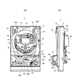
以下、本発明による好適な一実施形態として、発射ハンドルを備えるパチンコ機について図面を参照しながら説明する。なお、図1(a)は本パチンコ機1の外部構造を表す正面図、図1(b)はその側面図、図2は本パチンコ機1の構造を表す背面図である。
Hereinafter, as a preferred embodiment of the present invention, a pachinko machine having a launch handle will be described with reference to the drawings. 1A is a front view showing the external structure of the
本パチンコ機1は、発射ハンドル30の回動操作に応じて球発射装置55が作動し、遊技球を遊技盤面部16に打ち出しながら遊技を行うもので、いわゆる確率変動等の大当たりが発生した状態でアタッカー19(開閉式の大入賞口)に遊技球が入球することにより、その入賞に対応する数の遊技球を皿ユニット20へ払い出すように構成されている。上記確率変動(確変当たり)とは、遊技盤面部16上の始動チャッカー18への入球の際に行われる抽選の結果、確変モードの大当たりが当選したとき、少なくとも当該確変モードによる遊技状態において次の大当たりを引くまでの間、遊技者に有利な付加価値を付与する特別な遊技状態を意味する。これに対し、当該特別な遊技状態にならない大当たりとして「通常当たり」がある。
In this
図1に示すように、本パチンコ機1は、木枠11と、当該木枠11に対して開閉可能に装着された前扉12とを備え構成されている。前扉12の前面には、透明ガラス板13を有するガラス枠14が開閉可能に装着され、前扉12の前面下方部分には、同じく硬質プラスチックで一体的に形成された皿ユニット20が開閉可能に装着されている。
As shown in FIG. 1, the
ガラス枠14の上部には、高輝度の発光ダイオードを有する演出用照明部41と、スピーカを有する演出用放音部42a、42bとが配設されている。また、ガラス枠14の上方左隅部には、同じく高輝度の発光ダイオードを有し、例えばガラス枠14の開放エラー等を光で報知するための報知用照明部43が配設されている。
On the upper part of the
なお、木枠11内には、前扉12を木枠11側へ閉めることで自動的に施錠し、且つ、ガラス枠14を前扉12側へ閉めることでも施錠する不図示の施錠装置が設けられ、ガラス枠14の前面右方部に形成されている鍵穴15に所定の鍵を挿入して開錠操作をすることにより、これらを開放することができるようになっている。
The
皿ユニット20には、賞球または貸球として供給される遊技球を一時的に貯留するための球受け部21が一体的に形成されている。球受け部21の右方内壁には賞球払出口22が形成され、当該賞球払出口22を通して後述する賞球払出装置53からの賞球または貸球が球受け部21へ払い出される。
The
また、皿ユニット20の右側には、遊技球を遊技盤面部16へ向けて打ち出すための発射ハンドル30が配置されている。すなわち、発射ハンドル30は、内蔵するバネによって左回転方向に常時付勢される回動操作部301を有し、当該バネの付勢力に抗して回動操作部301が右回転方向に操作されると、球発射装置55を作動して回動操作部301の回動角度に応じた打撃力で遊技球が打ち出されるようになっている。
In addition, on the right side of the
また、皿ユニット20の下方部には、本パチンコ機1の遊技に係る案内を音声出力するためのスピーカを有する案内用放音部25が配設されている。
In addition, a guide
また、皿ユニット20の中央には、球受け部21上の遊技球を球発射装置55付近から皿ユニット20底部の球排出口23を通して下方へ排出させる球抜きボタン24aと、球受け部21上の遊技球を賞球払出口22付近から球排出口23を通して排出させる球抜きボタン24bが設けられている。
Further, in the center of the
前扉12に設けられている遊技盤面部16には、落下する遊技球を衝突させてその方向を偶発的に変更する釘が複数打設されている。また、遊技盤面部16には、入賞口に遊技球が入ることで入賞し、同時に乱数抽選を起動させるチャッカー18、及び遊技球が通過することで乱数抽選を起動させるパスゲート等が適宜の位置に複数配置されている。また、開閉式の入賞口を有するアタッカー19が下方位置に配置されている。アタッカー19は、大当たり等の入賞が確定すると、一定時間又は一定数の遊技球が入球するまで開放すると共に、開放時に遊技球が入ると通常よりも多くの賞球を払い出すので、入賞の確率を遊技者に有利に変動させることができる。
A plurality of nails are formed on the game
遊技盤面部16の略中央には矩形の表示窓44が形成された演出図柄表示部が配置され、遊技盤面部16の裏側に液晶ユニット58が表示窓44に面して装着されている。これにより、表示窓44を通して、液晶ユニット58が表示する演出図柄映像(例えば大当たり抽選の様子や当選結果を演出するような動画像)を遊技者が目視できるようになっている。
An effect symbol display part in which a
次に、図2を参照し、本パチンコ機1の背面側の構造を説明する。本パチンコ機1の木枠11中央には、CPU(またはマイコン)を実装しパチンコ機1の全体動作を集中制御する主制御基板51が配置されている。主制御基板51の上方には、液晶ユニット58等の映像表示装置が配置されている。また、液晶ユニット58の左方には、サブ制御基板52が配置されている。サブ制御基板52は、液晶ユニット58に対して映像表示の制御を行う映像表示制御部や、上述した演出用照明部41及び演出用放音部42a、42bに光または音による演出を行わせる制御を行う照明及び音響制御部を搭載している。
Next, the structure of the back side of the
木枠11の上部には、遊技島に設備される図示しない玉補給樋から賞球用として補給される遊技球を一時的に受ける賞球タンク54が配置されている。木枠11の中央部右方には、賞球タンク54に貯留されている遊技球を入賞に応じて皿ユニット20の球受け部21へ払い出す賞球払出装置53が設けられている。
On the upper part of the
木枠11の下部には、払出制御基板56、球発射装置55、及び電源ユニット57がそれぞれ配置されている。
Under the
払出制御基板56は、チャッカー17、18またはアタッカー19へ遊技球が入球し、または遊技者によって遊技球の貸し出し操作がされたとき、賞球払出装置53を作動して所定数の賞球または貸球を払い出す制御を行う。球発射装置55は、発射ハンドル30の回動操作に応じて、球受け部21に貯留されている遊技球を一球づつ遊技盤面部16へ打ち出す装置である。電源ユニット57は、主制御基板51等の各種制御基板、及び球発射装置55等の各種内蔵機器(装置)へ配電する配電回路が形成されており、本パチンコ機1の動作に必要な電力を各所に供給する。
The
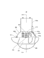
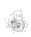
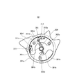
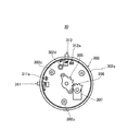
次に、本パチンコ機1に取り付けられている発射ハンドル30の構造を説明する。なお、図3は、発射ハンドル30の外観構造を表す平面図、図4は、図3に示すA−A線で切断した、発射ハンドル30の内部構造を表す部分断面図、図5は、図4に示す矢印位置Bから見た、前カバー303が取り外された状態の発射ハンドル30の内部構造を表す正面図、図6は、図4に示す矢印位置Cから見た、回動操作部301が取り外された状態の発射ハンドル30の内部構造を表す正面図である。
Next, the structure of the launch handle 30 attached to the
これらの図を参照し、発射ハンドル30は、遊技者によって回動操作される回動操作部301と、支持部材302と、前カバー303等の部材が組み立てられてユニット化されたものであり、支持部材302に形成されている取付け部302bを介してパチンコ機1の皿ユニット20に装着される。
With reference to these drawings, the launch handle 30 is a unit obtained by assembling a
支持部材302は、略半球形状の収容体であるケース部302aと、パチンコ機1の皿ユニット20に当該発射ハンドル30のユニットを装着するための取付け部302bとを備え、これらが一体的に形成されている。
The
支持部材302のケース部302aの外周部分には、球貸しスイッチ312と、返却スイッチ313と、図柄短縮スイッチ314が配列されている。また、各機能スイッチ312、313、314に隣接する一方側には、遊技の進行状況に応じて各スイッチの操作が有効か無効かを示すランプである報知ランプ312a、313b、314bがそれぞれ配置されている。また、各スイッチ312、313、314に隣接する他方側には、「球貸」、「返却」、「短縮」等の文字が印字された各スイッチの操作機能の内容を遊技者に容易に認識させるための機能標識部が設けられている。また、この機能標識部は文字のみに限らず、スイッチの機能内容について識別力を有する記号、図柄、またはこれらを組み合わせて表記されるものであってもよい。
A
なお、球貸しスイッチ312は、押圧操作されることで、例えばパチンコ機1に隣接して設けられるCR玉貸装置から所定数の遊技球を皿ユニット20へ払い出すための操作スイッチであり、また、返却スイッチ313は、上記CR玉貸装置に装填されているCRカードを排出させるための操作スイッチである。また、図柄短縮スイッチ314は、演出図柄表示部による演出図柄の演出時間を短縮するための操作スイッチである。
The
また、同じくケース部302aの外周であって上記各スイッチ312、313、314から左方向へ約90度位相をずらした位置に、単発スイッチ311が配置されている。なお、単発スイッチ311は、発射ハンドル30による連続発射を一時的に停止させるための操作スイッチである。単発スイッチ311に隣接してケース部302aの外周部分には、遊技の進行に応じて単発スイッチ311の操作が有効か無効かを示す報知ランプ311aが配置されている。
Similarly, a
図4に示すように、ケース部302a内壁の中心軸位置には、歯車305の軸部を受ける軸受部302eが形成されている。また、前カバー303の接続柱部303b先端と接続する接続筒部302cと、バネ304の一端を止めるための支柱部302dとが、ケース部302a内壁から前カバー303側へ延びて形成されている。なお、接続筒部302cの内部は、前カバー303とネジ止めする小ネジを収容するため空洞となっている。
As shown in FIG. 4, a bearing
また、支持部材302のケース部302aには、可変抵抗器307(ポテンショメータ)が取り付けられている。可変抵抗器307の軸には歯車306が固着され、回動操作部301と連動する歯車305と歯合している。
A variable resistor 307 (potentiometer) is attached to the
前カバー303は、略半球形状の蓋体であり、その内壁には回動操作部301の軸部301cを受ける軸受部303aが形成され、また、支持部材302と接続するための接続柱部303bが、支持部材302側の上記接続筒部302cと対応する位置にそれぞれ形成されている。
The
図5に示すように、回動操作部301は、指掛け用の突起部を複数有する円筒部301aと、円筒部301aの内側を塞ぐ円盤部301bと、円盤部301b中心に設けられる軸部301cとを備え、これらが一体的に形成されている。
As shown in FIG. 5, the
また、円盤部301bには、支持部材302の接続筒部302cまたは支柱部302dを通すための円弧状の孔301d、301eと、上記歯車305の側面に形成されている突起部を遊嵌させる遊嵌孔301fが軸部301cに隣接して形成されている。
Further, in the
すなわち、支持部材302と前カバー303とは、回動操作部301の円筒部301aを嵌合して挟み、接続筒部302c及び接続柱部303bの先端同士を接続筒部302c側から挿入する小ネジでネジ止め固着される。これにより、回動操作部301は、その軸部301cが前カバー303の軸受部303aに軸支されると共に、その円筒部301aの両縁部分が支持部材302及び前カバー303の周縁部分によって摺動可能に支持されることで、支持部材302及び前カバー303に対して回動可能に取り付けられる。
In other words, the
回動操作部301の軸部301cには、ねじりコイルバネであるバネ304が巻回されている。そして、バネ304の一端が支持部材302の支柱部302dに小ネジで固定され、バネ304の他端が回動操作部301の円盤部301bに係止されることで、回動操作部301は常時左回転方向に付勢されている。
A
図5に示されるように、発射ハンドル30は、非操作状態においては、円盤部301bの孔301d、301eの左回転方向始端に支持部材302の接続筒部302cが当接し、発射ハンドル30の回動操作部301が最大量回動操作されると、孔301d、301eの左回転方向終端に上記接続筒部302cが当接する。すなわち、孔301d、301eの長さ寸法により、回動操作部301の回動操作範囲が制限されている。
As shown in FIG. 5, when the firing handle 30 is not operated, the
かかる構成の発射ハンドル30は、回動操作部301がバネ304の付勢力に抗しながら右回転方向に操作されると、円盤部301bに遊嵌する歯車305が連動し、これに歯合する歯車306を介して可変抵抗器307の軸部を回転するように構成されている。これにより、例えば可変抵抗器307に一定の電流を供給すれば、回動操作部301の回動操作角度に応じた電圧信号を可変抵抗器307から得ることができるように構成されている。
In the launch handle 30 having such a configuration, when the
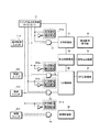
次に、図7に示す制御ブロック図を参照し、パチンコ機1の本発明に係る制御システムを説明する。
Next, a control system according to the present invention of the
パチンコ機1本体内に設けられている主制御基板51には、演出図柄表示部62が接続され、遊技の進行に応じて演出図柄映像を表示させる。また、主制御基板51には払出制御基板56が接続され、主制御基板51は、入賞口へ遊技球が入球した際に払出制御基板56を制御して賞球払出装置53を作動し、入賞の種類に応じた数の遊技球(賞球)を払い出させる制御を行う。
An effect symbol display unit 62 is connected to the
また、払出制御基板56にはCR制御部60が接続されている。CR制御部60は、パチンコ機1に隣接して設けられているCR玉貸装置61に遊技者がCRカードを装填し球貸しスイッチ312が操作されると、払出制御基板56を制御して所定数の遊技球(貸球)を賞球払出装置53によって払い出させる。
A CR control unit 60 is connected to the
図柄短縮スイッチ314は、ゲート回路71を介して主制御基板51へ操作信号を送出する。すなわち、スイッチ出力制御部70が例えば高電圧レベルのゲート信号T1を出力することによってゲート回路71が開状態(スルー)に制御されているとき、図柄短縮スイッチ314による操作が有効となり、この時点で図柄短縮スイッチ314が操作されると、主制御基板51は演出図柄表示部62よる演出図柄表示の演出時間を短縮させる。
The
球貸しスイッチ312及び返却スイッチ313は、ゲート回路72、73を介してCR制御部60へ操作信号を送出する。すなわち、スイッチ出力制御部70がゲート回路72を開状態(スルー)に制御にしている時点で球貸しスイッチ312が操作されると、CR制御部60は払出制御基板56を制御して所定数の遊技球を貸し出させる。また、スイッチ出力制御部70がゲート回路73を開状態(スルー)に制御にしている時に返却スイッチ313が操作されると、CR制御部60はCR玉貸装置61に対してCRカードを排出(返却)させる。
The
なお、上記球貸しスイッチ312及び返却スイッチ313は、ゲート回路72、73を介して払出制御基板56へ操作信号を送出するものであってもよい。
The
また、単発スイッチ311は、ゲート回路74を介して球発射装置55へ操作信号を送出する。すなわち、スイッチ出力制御部70がゲート回路74を開状態(スルー)に制御にしている時、単発スイッチ311が操作されると、球発射装置55は遊技球の連続打撃発射を停止させる。
The
主制御基板51は、パチンコ機1の現在進行中の遊技状態、すなわち、通常遊技状態か、通常当たり状態か、大当たり(確変当たり)状態か、又は待機状態か等、何れの遊技状態にあるのかを示す情報をスイッチ出力制御部70へ常時送出している。また、主制御基板51は、演出図柄表示部62の動作状態、及びCR玉貸装置61の動作状態(例えばCRカードの装填状態、CRカードが保有するポイント数)等、各種装置の動作に係る情報もスイッチ出力制御部70へ送出している。
The
スイッチ出力制御部70は、主制御基板51が示す当該パチンコ機1の現在の遊技状態に応じて、図柄短縮スイッチ314、球貸しスイッチ312、返却スイッチ313、及び単発スイッチ311の各スイッチ操作を有効又は無効にするゲート信号T1〜T4を各ゲート回路71〜74へ送出する。
The switch
例えば、当該パチンコ機1が大当たり中にあるときには、スイッチ出力制御部70は、ゲート回路71、73、74を開状態(スルー)にする高電圧レベルのゲート信号T1、T3、T4を送出することで、図柄短縮スイッチ314と、CRカード返却スイッチ313と、単発スイッチ311の操作を有効にする。同時に、スイッチ出力制御部70は、ゲート回路72に対しては閉状態(禁止)にする低電圧レベルのゲート信号T2を送出する。これにより、パチンコ機1が大当たり中にあっては、球貸しスイッチ312の操作を無効にし、仮に遊技者が誤って球貸しスイッチ312を操作したとしても賞球払出装置53による遊技球の貸し出し動作は行われないようになっている。
For example, when the
また、スイッチ出力制御部70は、上記各ゲート回路71〜74に対して送出する各ゲート信号T1〜T4を分岐して各スイッチに隣接する報知ランプ311a、312a、313a、314aを駆動する。例えば、上述した大当たり時において、図柄短縮スイッチ314と、返却スイッチ313と、単発スイッチ311の操作が有効である場合に、これらの各ゲート回路71、73、74を制御する高電圧レベルのゲート信号T1、T3、T4が各スイッチに隣接する報知ランプ314a、313a、311aに供給され、これら報知ランプを点灯させることで当該報知ランプに隣接するスイッチの操作が有効であることを遊技者に報知する。同時に、球貸しスイッチ312に隣接する報知ランプ312aは、低電圧レベルのゲート信号が供給され、このためランプが消灯し操作が無効であることを報知する。
The switch
なお、各報知ランプ311a〜314aは、例えば赤と青のそれぞれの色を発光する発光素子の組から構成されるものでもよい。例えば、図柄短縮スイッチ314と、返却スイッチ313と、単発スイッチ311の操作を有効にする高電圧レベルのゲート信号T1、T3、T4がスイッチ出力制御部70から発行され、同時に球貸しスイッチ312の操作を無効にする低電圧レベルのゲート信号T2が発行されたとき、報知ランプ314a、313a、311aは、青色の発光素子が点灯することで隣接するスイッチの操作が有効である旨を報知し、且つ報知ランプ312aは、赤色の発光素子が点灯して球貸しスイッチ312の操作が無効であることを報知する。
In addition, each
かかる構成の発射ハンドル30を備えるパチンコ機1によれば、発射ハンドル30に各種機能スイッチ311〜314を設けたので、遊技者は、発射ハンドル30を操作しながら所望の遊技操作を行うことができる。
According to the
また、発射ハンドル30に配設される各種機能スイッチに隣接して、スイッチ操作の有効又は無効を遊技の進行に応じて報知する報知ランプ311a〜314aを配置したので、遊技者は使用可能な機能スイッチを容易に認識できる。このため、遊技操作に係る利便性が向上すると共に各機能スイッチの誤操作が効果的に防止される。
In addition, adjacent to the various function switches arranged on the
また、遊技の進行に応じて各機能スイッチ311〜314の操作を無効にするゲート回路71〜74を設けたので、仮に遊技者が遊技の進行とは矛盾するスイッチ操作を行ったとしても当該スイッチ操作は機能しないこととなる。このため、遊技者の誤操作によって遊技進行の混乱を招くことはなく、遊技の興趣を失うこともない。
In addition, since the
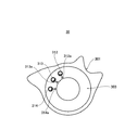
なお、本発明に係る機能スイッチ及び報知ランプの配置位置は、例えば図8に示すように、発射ハンドル30の前カバー303に設けられるものであってもよい。このように、遊技操作に係る各種機能スイッチを発射ハンドル30の適宜の位置に設けることで、パチンコ機1の操作性を向上させることができる。
In addition, the arrangement positions of the function switch and the notification lamp according to the present invention may be provided on the
また、上述した実施の形態においては、発射ハンドル30に設けられ遊技進行に応じてその機能が制限される機能スイッチとして、単発スイッチ311、球貸しスイッチ312、返却スイッチ313、図柄短縮スイッチ314をそれぞれ例示列挙して説明したが、実際に発明を実施する上では、上記各機能スイッチの全てについてそのスイッチ機能を有効又は無効に制限しまた報知ランプが設けられることを要しない。例えば、単発スイッチ311については、上述したゲート回路74を介さずに球発射装置55へ操作信号を送出させるようにして、遊技の進行に制限されず独立して機能する機能スイッチとして発射ハンドル30に設けてもよい。また、上記機能スイッチ311〜314以外の遊技操作を行うための機能スイッチを発射ハンドル30に設け、遊技の進行に応じてそのスイッチ機能を制限し且つその有効又は無効を報知する報知ランプを設けてもよいことは言うまでもない。
In the above-described embodiment, the
1…パチンコ機、 11…木枠、 12…前扉、
13…透明ガラス板、 14…ガラス枠、 15…鍵穴、
16…遊技盤面部、 17、18…チャッカー、
19…アタッカー、 20…皿ユニット、21…球受け部、
22…賞球払出口、 23…球排出口、
30…発射ハンドル、 41…演出用照明部、
42a、42b…演出用放音部、
43…報知用照明部、 44…表示窓、
51…主制御基板、 52…サブ制御基板、 53…賞球払出装置、
54…賞球タンク、 55…球発射装置、 56…払出制御基板、
57…電源ユニット、 58…液晶ユニット、
60…CR制御部、 61…CR玉貸装置、 62…演出図柄表示部、
70…スイッチ出力制御部、 71、72、73、74…ゲート回路、
301…回動操作部、 301a…円筒部、 301b…円盤部、
301c…軸部、 301d…孔、 301e…孔、301f…遊嵌孔、
302…支持部材、 302a…ケース部、 302b…取付け部、
302c…接続筒部、 302d…支柱部、302e…軸受部、
303…前カバー、 303a…軸受部、 303b…接続柱部、
304…バネ、 305…歯車、 306…歯車、 307…可変抵抗器、
311…単発スイッチ、 311a…報知ランプ、
312…球貸しスイッチ、 312a…報知ランプ
313…返却スイッチ、 313a…報知ランプ、
314…図柄短縮スイッチ、 314a…報知ランプ
1 ... Pachinko machine, 11 ... Wooden frame, 12 ... Front door,
13 ... Transparent glass plate, 14 ... Glass frame, 15 ... Keyhole,
16 ... Game board surface part, 17, 18 ... Chucker,
19 ... Attacker, 20 ... Dish unit, 21 ... Ball holder,
22 ... Award ball outlet, 23 ... Ball outlet,
30 ... Launch handle, 41 ... Illumination section for production,
42a, 42b ... Sound emission part for production,
43 ... Notification lighting section, 44 ... Display window,
51 ...
54 ... Prize ball tank, 55 ... Ball launcher, 56 ... Dispensing control board,
57 ... Power supply unit, 58 ... Liquid crystal unit,
60 ... CR control unit, 61 ... CR ball lending device, 62 ... Production symbol display unit,
70: Switch
301: Rotation operation part, 301a ... Cylindrical part, 301b ... Disk part,
301c ... shaft, 301d ... hole, 301e ... hole, 301f ... free fitting hole,
302 ...
302c ... Connection cylinder part, 302d ... Strut part, 302e ... Bearing part,
303 ... Front cover, 303a ... Bearing part, 303b ... Connection column part,
304 ... Spring, 305 ... Gear, 306 ... Gear, 307 ... Variable resistor,
311: Single switch, 311a: Notification lamp,
312 ... Ball lending switch, 312a ...
314 ... Symbol shortening switch, 314a ... Notification lamp
Claims (10)
前記パチンコ遊技機の遊技に係る操作をそれぞれ行う複数の機能スイッチと、
前記各機能スイッチに隣接し当該機能スイッチによる遊技操作の有効又は無効を前記パチンコ遊技機の遊技進行の状況に応じて報知する報知ランプをそれぞれ備えることを特徴とする発射ハンドル。 A launching handle for launching a game ball to the gaming board surface of the pachinko gaming machine according to a rotation operation provided on the front surface of the pachinko gaming machine,
A plurality of function switches for performing operations related to the game of the pachinko gaming machine,
A launching handle that is provided with a notification lamp adjacent to each function switch for notifying whether a game operation by the function switch is valid or invalid according to the progress of the game of the pachinko gaming machine.
前記支持部材とほぼ同径であって当該支持部材に対して回動可能に取り付けられる円筒形状の回動操作部材と、
前記回動操作部材内を貫通して前記支持部材と接続し当該回動操作部の前面を覆う蓋部材とを備え、
前記複数の機能スイッチと前記各報知ランプは、前記支持部材の外周面に配列されていることを特徴とする請求項1に記載の発射ハンドル。 A support member fixed to the main body of the pachinko gaming machine;
A cylindrical rotation operation member that is substantially the same diameter as the support member and is rotatably attached to the support member;
A lid member penetrating through the rotation operation member and connected to the support member and covering the front surface of the rotation operation unit;
The firing handle according to claim 1, wherein the plurality of function switches and the notification lamps are arranged on an outer peripheral surface of the support member.
前記支持部材とほぼ同径であって当該支持部材に対して回動可能に取り付けられる円筒形状の回動操作部材と、
前記回動操作部材内を貫通して前記支持部材と接続し当該回動操作部の前面を覆う蓋部材とを備え、
前記複数の機能スイッチと前記各報知ランプは、前記蓋部材の表面に配列されていることを特徴とする請求項1に記載の発射ハンドル。 A support member fixed to the main body of the pachinko gaming machine;
A cylindrical rotation operation member that is substantially the same diameter as the support member and is rotatably attached to the support member;
A lid member penetrating through the rotation operation member and connected to the support member and covering the front surface of the rotation operation unit;
The firing handle according to claim 1, wherein the plurality of function switches and the notification lamps are arranged on a surface of the lid member.
前記発射ハンドルは、当該パチンコ遊技機の遊技に係る操作をそれぞれ行う複数の機能スイッチと、
前記各機能スイッチに隣接し当該機能スイッチによる遊技操作の有効又は無効を当該パチンコ遊技機の遊技進行の状況に応じて報知する報知ランプをそれぞれ備えることを特徴とするパチンコ遊技機。 A pachinko gaming machine having a launching handle for performing an operation of launching a game ball onto a game board surface,
The firing handle includes a plurality of function switches for performing operations related to the game of the pachinko gaming machine,
A pachinko gaming machine that is provided with a notification lamp adjacent to each function switch for notifying validity or invalidity of a game operation by the function switch according to the progress of the game of the pachinko gaming machine.
前記支持部材とほぼ同径であって当該支持部材に対して回動可能に取り付けられる円筒形状の回動操作部材と、
前記回動操作部材内を貫通して前記支持部材と接続し当該回動操作部の前面を覆う蓋部材とを備え、
前記複数の機能スイッチと前記各報知ランプは、前記支持部材の外周面に配列されていることを特徴とする請求項6に記載のパチンコ遊技機。 The launch handle is a support member fixed to the main body of the pachinko gaming machine,
A cylindrical rotation operation member that is substantially the same diameter as the support member and is rotatably attached to the support member;
A lid member penetrating through the rotation operation member and connected to the support member and covering the front surface of the rotation operation unit;
The pachinko gaming machine according to claim 6, wherein the plurality of function switches and the notification lamps are arranged on an outer peripheral surface of the support member.
前記支持部材とほぼ同径であって当該支持部材に対して回動可能に取り付けられる円筒形状の回動操作部材と、
前記回動操作部材内を貫通して前記支持部材と接続し当該回動操作部の前面を覆う蓋部材とを備え、
前記複数の機能スイッチと前記各報知ランプは、前記蓋部材の表面に配列されていることを特徴とする請求項6に記載のパチンコ遊技機。 The launch handle is a support member fixed to the main body of the pachinko gaming machine,
A cylindrical rotation operation member that is substantially the same diameter as the support member and is rotatably attached to the support member;
A lid member penetrating through the rotation operation member and connected to the support member and covering the front surface of the rotation operation unit;
The pachinko gaming machine according to claim 6, wherein the plurality of function switches and the notification lamps are arranged on a surface of the lid member.
Priority Applications (1)
| Application Number | Priority Date | Filing Date | Title |
|---|---|---|---|
| JP2004119162A JP2005296446A (en) | 2004-04-14 | 2004-04-14 | Shooting handle and pachinko game machine with the same |
Applications Claiming Priority (1)
| Application Number | Priority Date | Filing Date | Title |
|---|---|---|---|
| JP2004119162A JP2005296446A (en) | 2004-04-14 | 2004-04-14 | Shooting handle and pachinko game machine with the same |
Publications (1)
| Publication Number | Publication Date |
|---|---|
| JP2005296446A true JP2005296446A (en) | 2005-10-27 |
Family
ID=35328700
Family Applications (1)
| Application Number | Title | Priority Date | Filing Date |
|---|---|---|---|
| JP2004119162A Pending JP2005296446A (en) | 2004-04-14 | 2004-04-14 | Shooting handle and pachinko game machine with the same |
Country Status (1)
| Country | Link |
|---|---|
| JP (1) | JP2005296446A (en) |
Cited By (6)
| Publication number | Priority date | Publication date | Assignee | Title |
|---|---|---|---|---|
| JP2008228997A (en) * | 2007-03-20 | 2008-10-02 | Heiwa Corp | Game machine |
| JP2008228998A (en) * | 2007-03-20 | 2008-10-02 | Heiwa Corp | Game machine |
| JP2009028347A (en) * | 2007-07-27 | 2009-02-12 | Olympia:Kk | Shooting handle of pinball game machine |
| JP2009131608A (en) * | 2007-11-08 | 2009-06-18 | Takeya Co Ltd | Ball hitting handle of game machine |
| JP2012110600A (en) * | 2010-11-26 | 2012-06-14 | Sanyo Product Co Ltd | Game machine |
| JP2021094090A (en) * | 2019-12-13 | 2021-06-24 | 株式会社平和 | Game machine |
Citations (4)
| Publication number | Priority date | Publication date | Assignee | Title |
|---|---|---|---|---|
| JPH0966132A (en) * | 1995-08-31 | 1997-03-11 | Okumura Yuki Kk | Shooting handle in pachinko game machine |
| JPH11226188A (en) * | 1998-02-10 | 1999-08-24 | Sanyo Bussan Kk | Shooting handle of pachinko game machine |
| JP2002165945A (en) * | 2000-12-01 | 2002-06-11 | Okumura Yu-Ki Co Ltd | Game machine |
| JP2002224309A (en) * | 2001-02-02 | 2002-08-13 | Fuji Shoji:Kk | Gaming machine |
-
2004
- 2004-04-14 JP JP2004119162A patent/JP2005296446A/en active Pending
Patent Citations (4)
| Publication number | Priority date | Publication date | Assignee | Title |
|---|---|---|---|---|
| JPH0966132A (en) * | 1995-08-31 | 1997-03-11 | Okumura Yuki Kk | Shooting handle in pachinko game machine |
| JPH11226188A (en) * | 1998-02-10 | 1999-08-24 | Sanyo Bussan Kk | Shooting handle of pachinko game machine |
| JP2002165945A (en) * | 2000-12-01 | 2002-06-11 | Okumura Yu-Ki Co Ltd | Game machine |
| JP2002224309A (en) * | 2001-02-02 | 2002-08-13 | Fuji Shoji:Kk | Gaming machine |
Cited By (7)
| Publication number | Priority date | Publication date | Assignee | Title |
|---|---|---|---|---|
| JP2008228997A (en) * | 2007-03-20 | 2008-10-02 | Heiwa Corp | Game machine |
| JP2008228998A (en) * | 2007-03-20 | 2008-10-02 | Heiwa Corp | Game machine |
| JP2009028347A (en) * | 2007-07-27 | 2009-02-12 | Olympia:Kk | Shooting handle of pinball game machine |
| JP2009131608A (en) * | 2007-11-08 | 2009-06-18 | Takeya Co Ltd | Ball hitting handle of game machine |
| JP2012110600A (en) * | 2010-11-26 | 2012-06-14 | Sanyo Product Co Ltd | Game machine |
| JP2021094090A (en) * | 2019-12-13 | 2021-06-24 | 株式会社平和 | Game machine |
| JP7198194B2 (en) | 2019-12-13 | 2022-12-28 | 株式会社平和 | game machine |
Similar Documents
| Publication | Publication Date | Title |
|---|---|---|
| JP5456728B2 (en) | Amusement stand | |
| JP2011200423A (en) | Game machine | |
| JP6609597B2 (en) | Game machine | |
| JP6327486B2 (en) | Game machine | |
| JP2009028246A (en) | Game table | |
| JPH11300011A (en) | Game machine | |
| JP4971082B2 (en) | Amusement stand | |
| JP2013052043A (en) | Game machine | |
| JP2012061077A (en) | Game machine | |
| JP2004057310A (en) | Slot machine | |
| JP5421797B2 (en) | Amusement stand | |
| JP2017189334A (en) | Game machine | |
| JP2006081809A (en) | Game machine | |
| JP6056011B2 (en) | Amusement stand | |
| JP2005296445A (en) | Game machine | |
| JP2012231974A (en) | Game machine | |
| JP2003210652A (en) | Game machine | |
| JP6707580B2 (en) | Amusement machine | |
| JP6605544B2 (en) | Game machine | |
| JP5761694B2 (en) | Amusement stand | |
| JP6212749B2 (en) | Game machine | |
| JP2005287870A (en) | Game machine | |
| JP7082817B2 (en) | Pachinko machine | |
| JP6707579B2 (en) | Amusement machine | |
| JP6368899B2 (en) | Amusement stand |
Legal Events
| Date | Code | Title | Description |
|---|---|---|---|
| A621 | Written request for application examination |
Effective date: 20070412 Free format text: JAPANESE INTERMEDIATE CODE: A621 |
|
| A131 | Notification of reasons for refusal |
Effective date: 20100202 Free format text: JAPANESE INTERMEDIATE CODE: A131 |
|
| A977 | Report on retrieval |
Free format text: JAPANESE INTERMEDIATE CODE: A971007 Effective date: 20100203 |
|
| A521 | Written amendment |
Free format text: JAPANESE INTERMEDIATE CODE: A523 Effective date: 20100316 |
|
| RD02 | Notification of acceptance of power of attorney |
Free format text: JAPANESE INTERMEDIATE CODE: A7422 Effective date: 20100316 |
|
| RD04 | Notification of resignation of power of attorney |
Free format text: JAPANESE INTERMEDIATE CODE: A7424 Effective date: 20100714 |
|
| A02 | Decision of refusal |
Free format text: JAPANESE INTERMEDIATE CODE: A02 Effective date: 20100806 |