JP2005296701A - Trigger type liquid spray - Google Patents
Trigger type liquid spray Download PDFInfo
- Publication number
- JP2005296701A JP2005296701A JP2004111990A JP2004111990A JP2005296701A JP 2005296701 A JP2005296701 A JP 2005296701A JP 2004111990 A JP2004111990 A JP 2004111990A JP 2004111990 A JP2004111990 A JP 2004111990A JP 2005296701 A JP2005296701 A JP 2005296701A
- Authority
- JP
- Japan
- Prior art keywords
- trigger type
- type liquid
- injection nozzle
- valve body
- guide
- Prior art date
- Legal status (The legal status is an assumption and is not a legal conclusion. Google has not performed a legal analysis and makes no representation as to the accuracy of the status listed.)
- Granted
Links
- 239000007788 liquid Substances 0.000 title claims abstract description 56
- 239000007921 spray Substances 0.000 title claims abstract description 11
- 125000006850 spacer group Chemical group 0.000 claims abstract description 15
- 238000002347 injection Methods 0.000 claims description 27
- 239000007924 injection Substances 0.000 claims description 27
- 238000007599 discharging Methods 0.000 claims description 4
- 238000005507 spraying Methods 0.000 abstract 1
- 230000037452 priming Effects 0.000 description 4
- 238000009825 accumulation Methods 0.000 description 1
- 239000003599 detergent Substances 0.000 description 1
- 239000003205 fragrance Substances 0.000 description 1
- 238000005086 pumping Methods 0.000 description 1
- 230000000630 rising effect Effects 0.000 description 1
- 230000037303 wrinkles Effects 0.000 description 1
Images

Landscapes
- Containers And Packaging Bodies Having A Special Means To Remove Contents (AREA)
Abstract
Description
本発明は、噴射ノズルの背面に規定の圧力でもって開閉する弁体を備えた蓄圧タイプのトリガー式液体噴出器に関し、内部のエアーを排出する初期プライミングが簡単にすみ、小さな力による操作レバーの牽曳でスムーズに液体を噴出させようとするものである。 The present invention relates to a pressure accumulation type trigger type liquid ejector having a valve body that opens and closes with a specified pressure on the back surface of an injection nozzle, and the initial priming for discharging the internal air can be easily performed. It is intended to smoothly eject liquid by checking.
黴取り剤や洗剤、衣料用糊剤、住居用ワックス、整髪剤、芳香剤等を入れた容器に装着され、容器内の内容物を操作レバーの牽曳によって適宜噴出させることができるトリガー式噴出器は、噴射ノズルを取り付けたボディに、液体の吸引、加圧、圧送を司るポンプ機構が組み込まれており、操作レバーにてポンプ機構を作動させることで内容物の効率的な噴出を可能にしている(例えば特許文献1参照)。 Trigger type spray that can be attached to a container containing wrinkle remover, detergent, clothing paste, residential wax, hair conditioner, fragrance, etc., and the contents in the container can be appropriately ejected by checking the operation lever. The pump is equipped with a pump mechanism that controls the suction, pressurization, and pumping of the liquid in the body to which the injection nozzle is attached. The pump mechanism is operated by the operation lever, enabling efficient ejection of the contents. (For example, refer to Patent Document 1).
ところで、従来の液体噴出器は、容器に充填されている液体の粘度にもよるが、そのほとんどが操作レバーを牽曳する際に比較的大きな力を必要とし、より小さな力でもって液体を円滑に噴射させることができる操作性の良好な噴出器の開発が望まれていた。 By the way, although the conventional liquid ejector depends on the viscosity of the liquid filled in the container, most of them require a relatively large force when checking the operation lever, and smooth the liquid with a smaller force. It has been desired to develop an ejector with good operability that can be sprayed on the surface.
本発明の課題は、内部構造の複雑化を招くことなしにより小さな力(牽曳力)でもって液体を噴出させることができる操作性の改善されたトリガー式液体噴出器を提案するところにある。 An object of the present invention is to propose a trigger type liquid ejector with improved operability capable of ejecting liquid with a small force (checking force) without complicating the internal structure.
本発明は、操作レバーを繰返し牽曳して容器内の液体を吸引、加圧するポンプと、このポンプによって加圧された内容物を噴射ノズルに向けて送給する送給経路を有するボディと、このボディの送給経路の出側端で往復移動可能に弾性支持され規定圧力を超える開放動作で該噴射ノズルを通して液体を外界に向けて噴出させる弁体とを備えたトリガー式液体噴出器であって、
前記送給経路に、その入側端から出側端に沿って延びる少なくとも1本の細溝を有し該送給経路の断面積を小さくして液体の送給量を少なくするスペーサを配置したことを特徴とするトリガー式液体噴出器である。
The present invention repeatedly pumps the operation lever to suck and pressurize the liquid in the container, and a body having a feeding path for feeding the contents pressurized by the pump toward the injection nozzle, A trigger-type liquid ejector comprising a valve body that is elastically supported so as to be reciprocally movable at the exit end of the feeding path of the body and ejects liquid toward the outside through the ejection nozzle through an opening operation exceeding a specified pressure. And
A spacer having at least one narrow groove extending from the inlet side end to the outlet side end in the feeding path and having a small cross-sectional area of the feeding path to reduce a liquid feeding amount is disposed. This is a trigger type liquid ejector.
上記の構成になる噴出器において、前記スペーサは、前記送給経路内に位置するシャフトと、該送給経路の出側端でシャフトの端部に一体連結し前記弁体を移動可能に保持するガイドからなるものとし、前記ボディに、前記ガイドを弁体とともに内側に納めるとともに、噴射ノズルをその先端で支持する連結部と、この連結部の外側に設けられ噴射ノズルの開口部又は凸部に嵌まり込んで噴射ノズルの抜けを防止する凸部又は開口を設けることができる。 In the ejector configured as described above, the spacer is integrally connected to an end portion of the shaft at the outlet end of the shaft located in the feeding path and the feeding path, and holds the valve body movably. The guide is composed of a guide, and the guide is housed inside the valve body together with the valve body, and a connecting portion that supports the injection nozzle at its tip, and an opening or a convex portion of the injection nozzle provided outside the connecting portion. A protrusion or opening can be provided that fits and prevents the injection nozzle from falling off.
また、前記スペーサは、前記送給経路内に位置するシャフトと、該送給経路の出側端でシャフトの端部に一体連結し前記弁体を移動可能に保持するガイドからなるものとし、前記ガイドに、ガイドの本体部分を弁体とともにその内側に納めて噴射ノズルを支持する前側連結部と、この前側連結部と一体になり噴射ノズルを前側連結部とともにボディの外側にて抜け止め係止する後側連結部とを設けることもできる。 The spacer includes a shaft positioned in the feeding path, and a guide integrally connected to an end of the shaft at the outlet end of the feeding path to hold the valve body movably. A guide connecting the main body part of the guide with the valve body inside the front side connecting part that supports the injection nozzle, and the front side connecting part integrated with the front side connecting part and retaining the injection nozzle on the outside of the body together with the front side connecting part It is also possible to provide a rear connecting portion.
さらに、前記弁体にその作動に合わせてその移動空間内の空気を噴射ノズル側に向けて排出する貫通孔を設けるか、あるいは、前記ガイドに前記弁体の作動に合わせてその移動空間内の空気をボディ側に向けて排出する貫通孔を設けることもできる。 Furthermore, the valve body is provided with a through hole for discharging the air in the moving space toward the injection nozzle in accordance with the operation thereof, or the guide is provided with a through hole in the moving space in accordance with the operation of the valve body. A through-hole that discharges air toward the body can also be provided.
さらにまた、本発明では、噴射ノズルの後端部に突き当たる先端を有しボディの全体を覆い隠すシュラウドあるいは噴射ノズルの先端を残して該噴射ノズル及びボディを覆い隠すシュラウドを配置することができる。 Furthermore, in the present invention, it is possible to arrange a shroud that has a front end that abuts against the rear end portion of the injection nozzle and covers the entire body, or a shroud that covers the injection nozzle and the body while leaving the front end of the injection nozzle.
液体の送給経路内にスペーサを配置して該経路の断面積を小さくすると操作レバーの一回当たりの牽曳に際して送給される液体の量が少なくなり、操作にかかる力は軽減される。 If a spacer is arranged in the liquid supply path and the cross-sectional area of the path is reduced, the amount of liquid supplied when checking the operation lever is reduced, and the force applied to the operation is reduced.
また、該スペーサを配置することでボディ内に存在する空気量が少なくなるので、空気と液体を置換する初期プライミング時に操作レバーの牽曳回数が少なくてすむ。 Further, since the amount of air existing in the body is reduced by arranging the spacer, the number of times of operation lever check-up can be reduced during the initial priming for replacing air and liquid.
以下、図面を参照して本発明をより具体的に説明する。
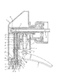
図1は本発明にしたがうトリガー式液体噴出器の実施の形態を示したものである。同図における1は枢支軸を介して揺動可能に保持される操作レバー、2は操作レバー1を繰返し牽曳して容器内の液体を吸引、加圧するポンプである。
Hereinafter, the present invention will be described more specifically with reference to the drawings.
FIG. 1 shows an embodiment of a trigger type liquid ejector according to the present invention. In the figure, reference numeral 1 denotes an operation lever that is swingably held via a pivot shaft, and 2 denotes a pump that repeatedly checks the operation lever 1 to suck and pressurize liquid in the container.
ポンプ2はシリンダー2aとこのシリンダー2a内で往復移動可能としたピストン2bからなる。
The
また、3は噴出器の基本的な骨格をなすボディであり、このボディ3にはポンプ2によって加圧された液体を噴射ノズルnに向けて送給する送給経路3aが設けられている。
4はボディ3の送給経路3aの出側端でスプリングSを介して弾性支持され規定圧力を超える開放動作で噴射ノズルnを通して液体を外界へ向けて噴出させる弁体である。この弁体4の前端壁には小孔が形成されており、弁体4の作動に合わせて移動空間t内の空気が小孔を通して速やかに排出されるためエアークッション現象を起こすことがなく、操作レバー1の作動がスムーズになる。
Reference numeral 4 denotes a valve body that is elastically supported via a spring S at the outlet end of the
5は送給経路3aに配置され、その断面積を小さくして液体の送給量を少なくするスペーサである。このスペーサ5は送給経路3aの入側端3a1から出側端3a2に沿って延びる細溝m1、m2を有するシャフト5a(スプライン軸のようなもの)と、送給経路3aの出側端3a2でシャフト5aの端部に一体連結して弁体4を移動可能に保持するガイド5bからなっている。なお、細溝m1、m2は必ずしも2本で構成されるものではなく、少なくとも1本以上あればよいものであり、その本数は適宜選択可能である。
さらに、6はボディ3に一体的に設けられガイド5bを弁体4とともに内側に納めるとともに、噴射ノズルnをその先端で支持する連結部、7は連結部6の外側に設けられ噴射ノズルnの外壁n1に形成された開口hに嵌まり込んで該噴射ノズルnの抜けを防止する凸部、8は噴射ノズルnの後端部に突き当たる先端を有しボディ3の全体を覆い隠すシュラウドである。
Further, 6 is provided integrally with the
容器内の液体を吸引する吸引管9、逆止弁10を通してシリンダー2aに吸引された液体を、操作レバー1のさらなる牽曳にて加圧、圧縮すると、該液体はボディ3の送給経路3aに存在する細溝m1、m2をとおり弁体5へと流れ込み、ここで規定圧力(スプリングSの弾性力を超える圧力)よりも高い圧力になることで弁体5が噴射のズルnの背面で形成される弁座vから離反(開放状態)し、かかる液体は噴射ノズルnから外界に向けて噴出されることになる。
When the liquid sucked into the
上記の構成になる液体噴出器は、加圧、圧縮された液体がスペーサ5の細溝m1、m2を通して送給されるので、液体の送給量は少なく、これがため操作レバー1を牽曳する力は小さくてすみ快適な操作が行える。 In the liquid ejector configured as described above, since the pressurized and compressed liquid is fed through the narrow grooves m 1 and m 2 of the spacer 5, the amount of liquid fed is small, and thus the operation lever 1 is checked. The power to hesitate is small and comfortable operation is possible.
スペーサ5はシャフト5aと弁体4を保持するガイド5bの一体物からなっており部品点数が増えることがないうえ、空気が入り込む内部空間が少ないので初期プライミングにおける牽曳回数が少なくてすみ、液体の迅速な噴出が可能となる(立ち上がりが早い)。
The
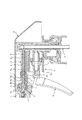
図2は本発明にしたがう噴出器の他の実施の形態を示したものである。
この例は、スペーサ5がシャフト5aとガイド5bからなるが、ガイド5bにはさらにガイド5bの本体部分を弁体4とともにその内側に納めて噴射ノズルnを支持する前側連結部5cと、この前側連結部5cと一体になり、噴射ノズルnを前側連結部5cとともにボディ3の外側にて抜け止め係止する後側連結部5dと、弁体4の作動(移動)に合わせてその移動空間t内の空気をボディ側に向けて排出する貫通孔5eが設けられている。
FIG. 2 shows another embodiment of the ejector according to the present invention.
In this example, the
この噴出器も、上掲図1に示したものと同様の要領で液体を噴出させることができるもので、図1に示した噴出器の弁体4の前端壁に設けた小孔に代えてガイド5bに貫通孔5eを形成することで前述の実施例と同様に、弁体4のd作動に合わせて移動空間t内の空気が貫通孔5eを通して速やかに排出されるためエアークッション現象を起こすことがなく、操作レバー1の作動がスムーズになる。
This ejector is also capable of ejecting liquid in the same manner as shown in FIG. 1, and instead of the small hole provided in the front end wall of the valve body 4 of the ejector shown in FIG. By forming the through
後側連結部5dをボディ3に抜け止め係止するには、図示の如く後側連結部5dに開口を形成しておき、この開口にボディ3の外側に設けた凸部7を係合させればよいが、後側連結部5dに凸部を設け、この凸部が係合する開口をボディ3に設けてもよく、この点についてはとくに限定されない。
In order to prevent the
図3(a)(b)は本発明にしたがう液体噴出器のさらに他の実施の形態を示したものである。 FIGS. 3 (a) and 3 (b) show still another embodiment of the liquid ejector according to the present invention.
この例は、内部構造については基本的に図1に示したものと共通するもので、シュラウド8のみが異なる。 In this example, the internal structure is basically the same as that shown in FIG. 1, and only the shroud 8 is different.
かかるシュラウド8は、噴射ノズルnの先端を残して該噴射ノズルn及びボディ3を覆い隠すことができるようにその先端部が延長されており、これにより噴射ノズルn及びボディ3への水分や塵等の侵入を確実に防止する。
The shroud 8 has its tip portion extended so as to cover the spray nozzle n and the
初期プライミングの回数が少なくてすみ、僅かな力で牽曳するだけで液体をスムーズに噴出させることができる操作性のよいトリガー式液体噴出器が提供できる。 It is possible to provide a trigger-type liquid ejector with good operability that requires only a small amount of initial priming and can smoothly eject liquid by simply checking with a small force.
1 操作レバー
2 ポンプ
2a シリンダー
2b ピストン
3 ボディ
4 弁体
5 スペーサ
5a シャフト
5b ガイド
5c 前側連結部
5d 後側連結部
5e 貫通孔
6 連結部
7 凸部
8 シュラウド
9 吸引管
10 逆止弁
n 噴射ノズル
S スプリング
t 移動空間
v 弁座
DESCRIPTION OF SYMBOLS 1
Claims (7)
前記送給経路に、その入側端から出側端に沿って延びる少なくとも1本の細溝を有し該送給経路の断面積を小さくして液体の送給量を少なくするスペーサを配置したことを特徴とするトリガー式液体噴出器。 A pump that repeatedly checks the operation lever to suck and pressurize the liquid in the container, a body having a supply path for supplying the liquid pressurized by the pump toward the injection nozzle, and the supply of the body A trigger type liquid ejector comprising a valve body that is elastically supported so as to be reciprocally movable at an exit end of a path and ejects liquid toward the outside through the ejection nozzle by an opening operation exceeding a specified pressure,
A spacer having at least one narrow groove extending from the inlet side end to the outlet side end in the feeding path and having a small cross-sectional area of the feeding path to reduce a liquid feeding amount is disposed. A trigger type liquid ejector characterized by that.
前記ボディに、前記ガイドを弁体とともに内側に納めるとともに、噴射ノズルをその先端で支持する連結部と、この連結部の外側に設けられ噴射ノズルの開口部又は凸部に嵌まり込んで噴射ノズルの抜けを防止する凸部又は開口を有する請求項1記載のトリガー式液体噴出器。 The spacer includes a shaft positioned in the feeding path, and a guide that is integrally connected to an end portion of the shaft at the outlet end of the feeding path and holds the valve body movably.
In the body, the guide is housed together with the valve body, and a connecting portion that supports the injection nozzle at the tip thereof, and an injection nozzle that is provided outside the connecting portion and fits in an opening or a convex portion of the injection nozzle. The trigger type liquid ejector according to claim 1, wherein the trigger type liquid ejector has a convex portion or an opening for preventing the omission.
前記ガイドに、ガイドの本体部分を弁体とともにその内側に納めて噴射ノズルをその先端で支持する前側連結部と、この前側連結部と一体になり噴射ノズルを前側連結部とともにボディの外側にて抜け止め係止する後側連結部とを設けた記載のトリガー式液体噴出器。 The spacer includes a shaft positioned in the feeding path, and a guide that is integrally connected to an end portion of the shaft at the outlet end of the feeding path and holds the valve body movably.
In the guide, the main body portion of the guide is housed inside the valve body together with the front connecting portion that supports the injection nozzle at the tip thereof, and the injection nozzle is integrated with the front connecting portion together with the front connecting portion on the outside of the body. The trigger type liquid ejector according to claim 1 provided with a rear side connecting portion for retaining and locking.
Priority Applications (1)
| Application Number | Priority Date | Filing Date | Title |
|---|---|---|---|
| JP2004111990A JP4451191B2 (en) | 2004-04-06 | 2004-04-06 | Trigger type liquid ejector |
Applications Claiming Priority (1)
| Application Number | Priority Date | Filing Date | Title |
|---|---|---|---|
| JP2004111990A JP4451191B2 (en) | 2004-04-06 | 2004-04-06 | Trigger type liquid ejector |
Publications (2)
| Publication Number | Publication Date |
|---|---|
| JP2005296701A true JP2005296701A (en) | 2005-10-27 |
| JP4451191B2 JP4451191B2 (en) | 2010-04-14 |
Family
ID=35328901
Family Applications (1)
| Application Number | Title | Priority Date | Filing Date |
|---|---|---|---|
| JP2004111990A Expired - Fee Related JP4451191B2 (en) | 2004-04-06 | 2004-04-06 | Trigger type liquid ejector |
Country Status (1)
| Country | Link |
|---|---|
| JP (1) | JP4451191B2 (en) |
Cited By (3)
| Publication number | Priority date | Publication date | Assignee | Title |
|---|---|---|---|---|
| JP2008272633A (en) * | 2007-04-26 | 2008-11-13 | Yoshino Kogyosho Co Ltd | Trigger type liquid spray |
| JP2008272634A (en) * | 2007-04-26 | 2008-11-13 | Yoshino Kogyosho Co Ltd | Trigger type liquid spray |
| JP2017197244A (en) * | 2016-04-28 | 2017-11-02 | 株式会社吉野工業所 | Trigger type bubble jetting machine |
-
2004
- 2004-04-06 JP JP2004111990A patent/JP4451191B2/en not_active Expired - Fee Related
Cited By (3)
| Publication number | Priority date | Publication date | Assignee | Title |
|---|---|---|---|---|
| JP2008272633A (en) * | 2007-04-26 | 2008-11-13 | Yoshino Kogyosho Co Ltd | Trigger type liquid spray |
| JP2008272634A (en) * | 2007-04-26 | 2008-11-13 | Yoshino Kogyosho Co Ltd | Trigger type liquid spray |
| JP2017197244A (en) * | 2016-04-28 | 2017-11-02 | 株式会社吉野工業所 | Trigger type bubble jetting machine |
Also Published As
| Publication number | Publication date |
|---|---|
| JP4451191B2 (en) | 2010-04-14 |
Similar Documents
| Publication | Publication Date | Title |
|---|---|---|
| US11498089B2 (en) | All plastic continuous spray trigger sprayer | |
| KR20160110486A (en) | Trigger-type liquid jetting device | |
| JP4451191B2 (en) | Trigger type liquid ejector | |
| JP4094440B2 (en) | Trigger type liquid ejector | |
| JP7345984B2 (en) | trigger type liquid squirt | |
| JP5567450B2 (en) | Trigger type liquid ejector | |
| JP5606801B2 (en) | Trigger type bubble jet | |
| JP4592433B2 (en) | Trigger type liquid ejector | |
| JP4767666B2 (en) | Trigger type liquid ejector | |
| JP4947591B2 (en) | Trigger type liquid ejector | |
| JP2009011885A (en) | Trigger type liquid ejector | |
| JP4489568B2 (en) | Former dispenser | |
| CN115968348A (en) | Trigger Liquid Dispenser | |
| JP2019210051A (en) | Trigger type sprayer | |
| JP5602500B2 (en) | Trigger type bubble jet | |
| JP5154097B2 (en) | Injection nozzle | |
| JP4594216B2 (en) | Double dispenser | |
| JP7798605B2 (en) | Trigger-type liquid sprayer | |
| JP7467005B2 (en) | Liquid Squirter | |
| JP7676271B2 (en) | Trigger-type liquid ejector | |
| JP2007136414A (en) | Trigger type liquid ejector | |
| JP6612181B2 (en) | Trigger type ejector | |
| JP3452283B2 (en) | Trigger sprayer | |
| JP2005296807A (en) | Trigger type liquid spray | |
| JP4279040B2 (en) | Trigger type liquid ejector |
Legal Events
| Date | Code | Title | Description |
|---|---|---|---|
| A621 | Written request for application examination |
Free format text: JAPANESE INTERMEDIATE CODE: A621 Effective date: 20061031 |
|
| A977 | Report on retrieval |
Free format text: JAPANESE INTERMEDIATE CODE: A971007 Effective date: 20090714 |
|
| A131 | Notification of reasons for refusal |
Free format text: JAPANESE INTERMEDIATE CODE: A131 Effective date: 20090728 |
|
| A521 | Request for written amendment filed |
Free format text: JAPANESE INTERMEDIATE CODE: A523 Effective date: 20090928 |
|
| RD03 | Notification of appointment of power of attorney |
Free format text: JAPANESE INTERMEDIATE CODE: A7423 Effective date: 20090928 |
|
| TRDD | Decision of grant or rejection written | ||
| A01 | Written decision to grant a patent or to grant a registration (utility model) |
Free format text: JAPANESE INTERMEDIATE CODE: A01 Effective date: 20100126 |
|
| A01 | Written decision to grant a patent or to grant a registration (utility model) |
Free format text: JAPANESE INTERMEDIATE CODE: A01 |
|
| A61 | First payment of annual fees (during grant procedure) |
Free format text: JAPANESE INTERMEDIATE CODE: A61 Effective date: 20100127 |
|
| R150 | Certificate of patent or registration of utility model |
Ref document number: 4451191 Country of ref document: JP Free format text: JAPANESE INTERMEDIATE CODE: R150 Free format text: JAPANESE INTERMEDIATE CODE: R150 |
|
| FPAY | Renewal fee payment (event date is renewal date of database) |
Free format text: PAYMENT UNTIL: 20130205 Year of fee payment: 3 |
|
| FPAY | Renewal fee payment (event date is renewal date of database) |
Free format text: PAYMENT UNTIL: 20140205 Year of fee payment: 4 |
|
| LAPS | Cancellation because of no payment of annual fees |