JP2005296821A - Gas separation composite membrane - Google Patents
Gas separation composite membrane Download PDFInfo
- Publication number
- JP2005296821A JP2005296821A JP2004117225A JP2004117225A JP2005296821A JP 2005296821 A JP2005296821 A JP 2005296821A JP 2004117225 A JP2004117225 A JP 2004117225A JP 2004117225 A JP2004117225 A JP 2004117225A JP 2005296821 A JP2005296821 A JP 2005296821A
- Authority
- JP
- Japan
- Prior art keywords
- gas separation
- composite membrane
- polymer
- porous body
- support
- Prior art date
- Legal status (The legal status is an assumption and is not a legal conclusion. Google has not performed a legal analysis and makes no representation as to the accuracy of the status listed.)
- Pending
Links
- 238000000926 separation method Methods 0.000 title claims abstract description 140
- 239000012528 membrane Substances 0.000 title claims abstract description 63
- 239000002131 composite material Substances 0.000 title claims abstract description 59
- 229920000642 polymer Polymers 0.000 claims abstract description 62
- 239000010409 thin film Substances 0.000 claims abstract description 40
- XLYOFNOQVPJJNP-UHFFFAOYSA-N water Substances O XLYOFNOQVPJJNP-UHFFFAOYSA-N 0.000 claims description 50
- 229920000573 polyethylene Polymers 0.000 claims description 40
- 239000007788 liquid Substances 0.000 claims description 33
- 239000010419 fine particle Substances 0.000 claims description 32
- 239000003795 chemical substances by application Substances 0.000 claims description 29
- 239000011148 porous material Substances 0.000 claims description 26
- 229920001296 polysiloxane Polymers 0.000 claims description 23
- 238000004519 manufacturing process Methods 0.000 claims description 17
- 125000003118 aryl group Chemical group 0.000 claims description 16
- 239000000203 mixture Substances 0.000 claims description 16
- 125000001931 aliphatic group Chemical group 0.000 claims description 9
- 239000013078 crystal Substances 0.000 claims description 7
- 229920001971 elastomer Polymers 0.000 claims description 7
- 238000002156 mixing Methods 0.000 claims description 5
- 239000011521 glass Substances 0.000 claims description 4
- 230000007480 spreading Effects 0.000 claims description 2
- 238000003892 spreading Methods 0.000 claims description 2
- 125000005462 imide group Chemical group 0.000 claims 1
- 230000035699 permeability Effects 0.000 abstract description 15
- 239000007789 gas Substances 0.000 description 129
- 238000000034 method Methods 0.000 description 35
- VYPSYNLAJGMNEJ-UHFFFAOYSA-N Silicium dioxide Chemical compound O=[Si]=O VYPSYNLAJGMNEJ-UHFFFAOYSA-N 0.000 description 27
- GTDPSWPPOUPBNX-UHFFFAOYSA-N ac1mqpva Chemical compound CC12C(=O)OC(=O)C1(C)C1(C)C2(C)C(=O)OC1=O GTDPSWPPOUPBNX-UHFFFAOYSA-N 0.000 description 21
- -1 polyethylene skeleton Polymers 0.000 description 21
- QVGXLLKOCUKJST-UHFFFAOYSA-N atomic oxygen Chemical compound [O] QVGXLLKOCUKJST-UHFFFAOYSA-N 0.000 description 18
- 239000001301 oxygen Substances 0.000 description 18
- 229910052760 oxygen Inorganic materials 0.000 description 18
- 239000002243 precursor Substances 0.000 description 17
- IJGRMHOSHXDMSA-UHFFFAOYSA-N Atomic nitrogen Chemical compound N#N IJGRMHOSHXDMSA-UHFFFAOYSA-N 0.000 description 13
- YXFVVABEGXRONW-UHFFFAOYSA-N Toluene Chemical compound CC1=CC=CC=C1 YXFVVABEGXRONW-UHFFFAOYSA-N 0.000 description 12
- DOIRQSBPFJWKBE-UHFFFAOYSA-N dibutyl phthalate Chemical compound CCCCOC(=O)C1=CC=CC=C1C(=O)OCCCC DOIRQSBPFJWKBE-UHFFFAOYSA-N 0.000 description 12
- 238000010521 absorption reaction Methods 0.000 description 11
- 230000004931 aggregating effect Effects 0.000 description 11
- 238000000605 extraction Methods 0.000 description 11
- 150000003949 imides Chemical group 0.000 description 11
- KPUWHANPEXNPJT-UHFFFAOYSA-N disiloxane Chemical class [SiH3]O[SiH3] KPUWHANPEXNPJT-UHFFFAOYSA-N 0.000 description 10
- 238000004898 kneading Methods 0.000 description 10
- 239000002245 particle Substances 0.000 description 10
- 229920001721 polyimide Polymers 0.000 description 10
- 239000000377 silicon dioxide Substances 0.000 description 10
- VGGSQFUCUMXWEO-UHFFFAOYSA-N Ethene Chemical compound C=C VGGSQFUCUMXWEO-UHFFFAOYSA-N 0.000 description 9
- 239000005977 Ethylene Substances 0.000 description 9
- 239000004642 Polyimide Substances 0.000 description 9
- 125000004432 carbon atom Chemical group C* 0.000 description 8
- 150000002430 hydrocarbons Chemical group 0.000 description 8
- 230000001427 coherent effect Effects 0.000 description 7
- 230000018044 dehydration Effects 0.000 description 7
- 238000006297 dehydration reaction Methods 0.000 description 7
- 239000002904 solvent Substances 0.000 description 7
- 229920001577 copolymer Polymers 0.000 description 6
- 238000011161 development Methods 0.000 description 6
- 229910052757 nitrogen Inorganic materials 0.000 description 6
- 239000004698 Polyethylene Substances 0.000 description 5
- 230000009477 glass transition Effects 0.000 description 5
- 239000000463 material Substances 0.000 description 5
- 239000003921 oil Substances 0.000 description 5
- 239000000126 substance Substances 0.000 description 5
- 238000009864 tensile test Methods 0.000 description 5
- 230000007704 transition Effects 0.000 description 5
- 239000005662 Paraffin oil Substances 0.000 description 4
- 230000000694 effects Effects 0.000 description 4
- 238000007667 floating Methods 0.000 description 4
- 238000002844 melting Methods 0.000 description 4
- 230000008018 melting Effects 0.000 description 4
- 125000001997 phenyl group Chemical group [H]C1=C([H])C([H])=C(*)C([H])=C1[H] 0.000 description 4
- 239000011164 primary particle Substances 0.000 description 4
- 230000008569 process Effects 0.000 description 4
- 229930195734 saturated hydrocarbon Natural products 0.000 description 4
- 125000006158 tetracarboxylic acid group Chemical group 0.000 description 4
- 229930195735 unsaturated hydrocarbon Natural products 0.000 description 4
- ZWEHNKRNPOVVGH-UHFFFAOYSA-N 2-Butanone Chemical compound CCC(C)=O ZWEHNKRNPOVVGH-UHFFFAOYSA-N 0.000 description 3
- UHOVQNZJYSORNB-UHFFFAOYSA-N Benzene Chemical compound C1=CC=CC=C1 UHOVQNZJYSORNB-UHFFFAOYSA-N 0.000 description 3
- 239000004699 Ultra-high molecular weight polyethylene Substances 0.000 description 3
- 230000001464 adherent effect Effects 0.000 description 3
- 150000004984 aromatic diamines Chemical class 0.000 description 3
- 230000000052 comparative effect Effects 0.000 description 3
- 150000004985 diamines Chemical class 0.000 description 3
- 238000001035 drying Methods 0.000 description 3
- 230000006870 function Effects 0.000 description 3
- 230000005484 gravity Effects 0.000 description 3
- 229920001903 high density polyethylene Polymers 0.000 description 3
- 239000004700 high-density polyethylene Substances 0.000 description 3
- 238000005259 measurement Methods 0.000 description 3
- 125000002496 methyl group Chemical group [H]C([H])([H])* 0.000 description 3
- 238000000465 moulding Methods 0.000 description 3
- VLKZOEOYAKHREP-UHFFFAOYSA-N n-Hexane Chemical compound CCCCCC VLKZOEOYAKHREP-UHFFFAOYSA-N 0.000 description 3
- 125000000843 phenylene group Chemical group C1(=C(C=CC=C1)*)* 0.000 description 3
- 238000012360 testing method Methods 0.000 description 3
- 125000002023 trifluoromethyl group Chemical group FC(F)(F)* 0.000 description 3
- 229920000785 ultra high molecular weight polyethylene Polymers 0.000 description 3
- NAWXUBYGYWOOIX-SFHVURJKSA-N (2s)-2-[[4-[2-(2,4-diaminoquinazolin-6-yl)ethyl]benzoyl]amino]-4-methylidenepentanedioic acid Chemical compound C1=CC2=NC(N)=NC(N)=C2C=C1CCC1=CC=C(C(=O)N[C@@H](CC(=C)C(O)=O)C(O)=O)C=C1 NAWXUBYGYWOOIX-SFHVURJKSA-N 0.000 description 2
- VTYYLEPIZMXCLO-UHFFFAOYSA-L Calcium carbonate Chemical compound [Ca+2].[O-]C([O-])=O VTYYLEPIZMXCLO-UHFFFAOYSA-L 0.000 description 2
- CURLTUGMZLYLDI-UHFFFAOYSA-N Carbon dioxide Chemical compound O=C=O CURLTUGMZLYLDI-UHFFFAOYSA-N 0.000 description 2
- MQIUGAXCHLFZKX-UHFFFAOYSA-N Di-n-octyl phthalate Natural products CCCCCCCCOC(=O)C1=CC=CC=C1C(=O)OCCCCCCCC MQIUGAXCHLFZKX-UHFFFAOYSA-N 0.000 description 2
- LFQSCWFLJHTTHZ-UHFFFAOYSA-N Ethanol Chemical compound CCO LFQSCWFLJHTTHZ-UHFFFAOYSA-N 0.000 description 2
- IMNFDUFMRHMDMM-UHFFFAOYSA-N N-Heptane Chemical compound CCCCCCC IMNFDUFMRHMDMM-UHFFFAOYSA-N 0.000 description 2
- 238000005054 agglomeration Methods 0.000 description 2
- 230000002776 aggregation Effects 0.000 description 2
- 125000000217 alkyl group Chemical group 0.000 description 2
- 230000008901 benefit Effects 0.000 description 2
- BJQHLKABXJIVAM-UHFFFAOYSA-N bis(2-ethylhexyl) phthalate Chemical compound CCCCC(CC)COC(=O)C1=CC=CC=C1C(=O)OCC(CC)CCCC BJQHLKABXJIVAM-UHFFFAOYSA-N 0.000 description 2
- 238000009835 boiling Methods 0.000 description 2
- 230000008859 change Effects 0.000 description 2
- 238000002485 combustion reaction Methods 0.000 description 2
- 238000006482 condensation reaction Methods 0.000 description 2
- 238000010924 continuous production Methods 0.000 description 2
- 230000007547 defect Effects 0.000 description 2
- 125000000816 ethylene group Chemical group [H]C([H])([*:1])C([H])([H])[*:2] 0.000 description 2
- 239000010408 film Substances 0.000 description 2
- 229910052731 fluorine Inorganic materials 0.000 description 2
- 125000001153 fluoro group Chemical group F* 0.000 description 2
- 238000005227 gel permeation chromatography Methods 0.000 description 2
- 238000010438 heat treatment Methods 0.000 description 2
- 125000004435 hydrogen atom Chemical group [H]* 0.000 description 2
- 229920001600 hydrophobic polymer Polymers 0.000 description 2
- 238000003475 lamination Methods 0.000 description 2
- 239000003960 organic solvent Substances 0.000 description 2
- 239000010690 paraffinic oil Substances 0.000 description 2
- XNGIFLGASWRNHJ-UHFFFAOYSA-N phthalic acid Chemical compound OC(=O)C1=CC=CC=C1C(O)=O XNGIFLGASWRNHJ-UHFFFAOYSA-N 0.000 description 2
- 239000004014 plasticizer Substances 0.000 description 2
- 150000007519 polyprotic acids Polymers 0.000 description 2
- 238000002360 preparation method Methods 0.000 description 2
- 238000012545 processing Methods 0.000 description 2
- 125000004805 propylene group Chemical group [H]C([H])([H])C([H])([*:1])C([H])([H])[*:2] 0.000 description 2
- 235000012239 silicon dioxide Nutrition 0.000 description 2
- 238000005245 sintering Methods 0.000 description 2
- BGHCVCJVXZWKCC-UHFFFAOYSA-N tetradecane Chemical compound CCCCCCCCCCCCCC BGHCVCJVXZWKCC-UHFFFAOYSA-N 0.000 description 2
- 239000011800 void material Substances 0.000 description 2
- VLDPXPPHXDGHEW-UHFFFAOYSA-N 1-chloro-2-dichlorophosphoryloxybenzene Chemical compound ClC1=CC=CC=C1OP(Cl)(Cl)=O VLDPXPPHXDGHEW-UHFFFAOYSA-N 0.000 description 1
- GWHLJVMSZRKEAQ-UHFFFAOYSA-N 3-(2,3-dicarboxyphenyl)phthalic acid Chemical compound OC(=O)C1=CC=CC(C=2C(=C(C(O)=O)C=CC=2)C(O)=O)=C1C(O)=O GWHLJVMSZRKEAQ-UHFFFAOYSA-N 0.000 description 1
- HWBVOOWDSUQMHR-UHFFFAOYSA-N 4-[1-(3,4-dicarboxyphenyl)-1,2,2,3,3,3-hexafluoropropyl]phthalic acid Chemical compound C1=C(C(O)=O)C(C(=O)O)=CC=C1C(F)(C(F)(F)C(F)(F)F)C1=CC=C(C(O)=O)C(C(O)=O)=C1 HWBVOOWDSUQMHR-UHFFFAOYSA-N 0.000 description 1
- NGMJQNYIDZLGFP-UHFFFAOYSA-N 4-[10-(4-aminophenoxy)decoxy]aniline Chemical compound C1=CC(N)=CC=C1OCCCCCCCCCCOC1=CC=C(N)C=C1 NGMJQNYIDZLGFP-UHFFFAOYSA-N 0.000 description 1
- JXFCYRAFQGPMTH-UHFFFAOYSA-N 4-[11-(4-aminophenoxy)undecoxy]aniline Chemical compound C1=CC(N)=CC=C1OCCCCCCCCCCCOC1=CC=C(N)C=C1 JXFCYRAFQGPMTH-UHFFFAOYSA-N 0.000 description 1
- NYYQMRVJKVNHRC-UHFFFAOYSA-N 4-[12-(4-aminophenoxy)dodecoxy]aniline Chemical compound C1=CC(N)=CC=C1OCCCCCCCCCCCCOC1=CC=C(N)C=C1 NYYQMRVJKVNHRC-UHFFFAOYSA-N 0.000 description 1
- BBHBBABNMUGQIN-UHFFFAOYSA-N 4-[13-(4-aminophenoxy)tridecoxy]aniline Chemical compound C1=CC(N)=CC=C1OCCCCCCCCCCCCCOC1=CC=C(N)C=C1 BBHBBABNMUGQIN-UHFFFAOYSA-N 0.000 description 1
- BQBKSNDUNFEQIE-UHFFFAOYSA-N 4-[18-(4-aminophenoxy)octadecoxy]aniline Chemical compound C1=CC(N)=CC=C1OCCCCCCCCCCCCCCCCCCOC1=CC=C(N)C=C1 BQBKSNDUNFEQIE-UHFFFAOYSA-N 0.000 description 1
- HHDFKOSSEXYTJN-UHFFFAOYSA-N 4-[2-(4-aminophenoxy)ethoxy]aniline Chemical compound C1=CC(N)=CC=C1OCCOC1=CC=C(N)C=C1 HHDFKOSSEXYTJN-UHFFFAOYSA-N 0.000 description 1
- JLLLOESJMWEAAO-UHFFFAOYSA-N 4-[3,4-dicarboxy-2-(trifluoromethyl)phenyl]-3-(trifluoromethyl)phthalic acid Chemical compound FC(F)(F)C1=C(C(O)=O)C(C(=O)O)=CC=C1C1=CC=C(C(O)=O)C(C(O)=O)=C1C(F)(F)F JLLLOESJMWEAAO-UHFFFAOYSA-N 0.000 description 1
- KWFFEQXPFFDJER-UHFFFAOYSA-N 4-[3-(4-aminophenoxy)propoxy]aniline Chemical compound C1=CC(N)=CC=C1OCCCOC1=CC=C(N)C=C1 KWFFEQXPFFDJER-UHFFFAOYSA-N 0.000 description 1
- LAFZPVANKKJENB-UHFFFAOYSA-N 4-[4-(4-aminophenoxy)butoxy]aniline Chemical compound C1=CC(N)=CC=C1OCCCCOC1=CC=C(N)C=C1 LAFZPVANKKJENB-UHFFFAOYSA-N 0.000 description 1
- MRTAEHMRKDVKMS-UHFFFAOYSA-N 4-[4-[4-(3,4-dicarboxyphenoxy)phenyl]sulfanylphenoxy]phthalic acid Chemical compound C1=C(C(O)=O)C(C(=O)O)=CC=C1OC(C=C1)=CC=C1SC(C=C1)=CC=C1OC1=CC=C(C(O)=O)C(C(O)=O)=C1 MRTAEHMRKDVKMS-UHFFFAOYSA-N 0.000 description 1
- SLHXQWDUYXSTPA-UHFFFAOYSA-N 4-[5-(4-aminophenoxy)pentoxy]aniline Chemical compound C1=CC(N)=CC=C1OCCCCCOC1=CC=C(N)C=C1 SLHXQWDUYXSTPA-UHFFFAOYSA-N 0.000 description 1
- GRFCDFDVGOXFPY-UHFFFAOYSA-N 4-[6-(4-aminophenoxy)hexoxy]aniline Chemical compound C1=CC(N)=CC=C1OCCCCCCOC1=CC=C(N)C=C1 GRFCDFDVGOXFPY-UHFFFAOYSA-N 0.000 description 1
- SURHEQARWKWZMT-UHFFFAOYSA-N 4-[8-(4-aminophenoxy)octoxy]aniline Chemical compound C1=CC(N)=CC=C1OCCCCCCCCOC1=CC=C(N)C=C1 SURHEQARWKWZMT-UHFFFAOYSA-N 0.000 description 1
- DFXGPEKKMXWHQU-UHFFFAOYSA-N 4-[9-(4-aminophenoxy)nonoxy]aniline Chemical compound C1=CC(N)=CC=C1OCCCCCCCCCOC1=CC=C(N)C=C1 DFXGPEKKMXWHQU-UHFFFAOYSA-N 0.000 description 1
- ZMPUYJLKSUAQEJ-UHFFFAOYSA-N 4-pentadecoxyaniline Chemical compound C(CCCCCCCCCCCCCC)OC1=CC=C(N)C=C1 ZMPUYJLKSUAQEJ-UHFFFAOYSA-N 0.000 description 1
- VQVIHDPBMFABCQ-UHFFFAOYSA-N 5-(1,3-dioxo-2-benzofuran-5-carbonyl)-2-benzofuran-1,3-dione Chemical compound C1=C2C(=O)OC(=O)C2=CC(C(C=2C=C3C(=O)OC(=O)C3=CC=2)=O)=C1 VQVIHDPBMFABCQ-UHFFFAOYSA-N 0.000 description 1
- QQGYZOYWNCKGEK-UHFFFAOYSA-N 5-[(1,3-dioxo-2-benzofuran-5-yl)oxy]-2-benzofuran-1,3-dione Chemical compound C1=C2C(=O)OC(=O)C2=CC(OC=2C=C3C(=O)OC(C3=CC=2)=O)=C1 QQGYZOYWNCKGEK-UHFFFAOYSA-N 0.000 description 1
- DAAGSOMXYMQJBC-UHFFFAOYSA-N C1(=CC=CC=C1)C1=C(C=CC(=C1C(=O)O)C(=O)O)C1=C(C(=C(C=C1)C(=O)O)C(=O)O)C1=CC=CC=C1 Chemical compound C1(=CC=CC=C1)C1=C(C=CC(=C1C(=O)O)C(=O)O)C1=C(C(=C(C=C1)C(=O)O)C(=O)O)C1=CC=CC=C1 DAAGSOMXYMQJBC-UHFFFAOYSA-N 0.000 description 1
- UGFAIRIUMAVXCW-UHFFFAOYSA-N Carbon monoxide Chemical compound [O+]#[C-] UGFAIRIUMAVXCW-UHFFFAOYSA-N 0.000 description 1
- 229920000089 Cyclic olefin copolymer Polymers 0.000 description 1
- MYMOFIZGZYHOMD-UHFFFAOYSA-N Dioxygen Chemical compound O=O MYMOFIZGZYHOMD-UHFFFAOYSA-N 0.000 description 1
- SECXISVLQFMRJM-UHFFFAOYSA-N N-Methylpyrrolidone Chemical compound CN1CCCC1=O SECXISVLQFMRJM-UHFFFAOYSA-N 0.000 description 1
- KETRRTNFIOJUNR-UHFFFAOYSA-N NC1=CC=C(OCCCCCCCCCCCCCCCCCCCCOC2=CC=C(C=C2)N)C=C1 Chemical compound NC1=CC=C(OCCCCCCCCCCCCCCCCCCCCOC2=CC=C(C=C2)N)C=C1 KETRRTNFIOJUNR-UHFFFAOYSA-N 0.000 description 1
- ZTTMIGKKGWFXQU-UHFFFAOYSA-N NC1=CC=C(OCCCCCCCCCCCCCCCCCCCOC2=CC=C(C=C2)N)C=C1 Chemical compound NC1=CC=C(OCCCCCCCCCCCCCCCCCCCOC2=CC=C(C=C2)N)C=C1 ZTTMIGKKGWFXQU-UHFFFAOYSA-N 0.000 description 1
- JPRMAFHCTGNZTK-UHFFFAOYSA-N NC1=CC=C(OCCCCCCCCCCCCCCCCCOC2=CC=C(C=C2)N)C=C1 Chemical compound NC1=CC=C(OCCCCCCCCCCCCCCCCCOC2=CC=C(C=C2)N)C=C1 JPRMAFHCTGNZTK-UHFFFAOYSA-N 0.000 description 1
- BMRZGPOGDNDCPK-UHFFFAOYSA-N NC1=CC=C(OCCCCCCCCCCCCCCCCOC2=CC=C(C=C2)N)C=C1 Chemical compound NC1=CC=C(OCCCCCCCCCCCCCCCCOC2=CC=C(C=C2)N)C=C1 BMRZGPOGDNDCPK-UHFFFAOYSA-N 0.000 description 1
- CTQNGGLPUBDAKN-UHFFFAOYSA-N O-Xylene Chemical compound CC1=CC=CC=C1C CTQNGGLPUBDAKN-UHFFFAOYSA-N 0.000 description 1
- 239000004743 Polypropylene Substances 0.000 description 1
- 239000004793 Polystyrene Substances 0.000 description 1
- UPDXVTHELHNFMF-UHFFFAOYSA-N [Si](O)(O)(O)O.[Si]=O Chemical compound [Si](O)(O)(O)O.[Si]=O UPDXVTHELHNFMF-UHFFFAOYSA-N 0.000 description 1
- 239000002253 acid Substances 0.000 description 1
- 125000004018 acid anhydride group Chemical group 0.000 description 1
- NIXOWILDQLNWCW-UHFFFAOYSA-N acrylic acid group Chemical group C(C=C)(=O)O NIXOWILDQLNWCW-UHFFFAOYSA-N 0.000 description 1
- 238000004378 air conditioning Methods 0.000 description 1
- 150000001298 alcohols Chemical class 0.000 description 1
- 125000003342 alkenyl group Chemical group 0.000 description 1
- 125000002947 alkylene group Chemical group 0.000 description 1
- 125000003277 amino group Chemical group 0.000 description 1
- 125000003710 aryl alkyl group Chemical group 0.000 description 1
- 230000005540 biological transmission Effects 0.000 description 1
- 238000007664 blowing Methods 0.000 description 1
- WKDNYTOXBCRNPV-UHFFFAOYSA-N bpda Chemical compound C1=C2C(=O)OC(=O)C2=CC(C=2C=C3C(=O)OC(C3=CC=2)=O)=C1 WKDNYTOXBCRNPV-UHFFFAOYSA-N 0.000 description 1
- 239000004566 building material Substances 0.000 description 1
- 229910000019 calcium carbonate Inorganic materials 0.000 description 1
- 239000001569 carbon dioxide Substances 0.000 description 1
- 229910002092 carbon dioxide Inorganic materials 0.000 description 1
- 229910002091 carbon monoxide Inorganic materials 0.000 description 1
- 238000006243 chemical reaction Methods 0.000 description 1
- 150000001875 compounds Chemical class 0.000 description 1
- 239000000498 cooling water Substances 0.000 description 1
- 238000005520 cutting process Methods 0.000 description 1
- 150000005690 diesters Chemical class 0.000 description 1
- 229910001882 dioxygen Inorganic materials 0.000 description 1
- BXKDSDJJOVIHMX-UHFFFAOYSA-N edrophonium chloride Chemical compound [Cl-].CC[N+](C)(C)C1=CC=CC(O)=C1 BXKDSDJJOVIHMX-UHFFFAOYSA-N 0.000 description 1
- 125000005678 ethenylene group Chemical group [H]C([*:1])=C([H])[*:2] 0.000 description 1
- 125000001495 ethyl group Chemical group [H]C([H])([H])C([H])([H])* 0.000 description 1
- 229920006242 ethylene acrylic acid copolymer Polymers 0.000 description 1
- 229910021485 fumed silica Inorganic materials 0.000 description 1
- 230000036541 health Effects 0.000 description 1
- 229920006158 high molecular weight polymer Polymers 0.000 description 1
- 238000007654 immersion Methods 0.000 description 1
- 239000010954 inorganic particle Substances 0.000 description 1
- 239000003273 ketjen black Substances 0.000 description 1
- 238000010030 laminating Methods 0.000 description 1
- 125000001570 methylene group Chemical group [H]C([H])([*:1])[*:2] 0.000 description 1
- 239000012046 mixed solvent Substances 0.000 description 1
- JCXJVPUVTGWSNB-UHFFFAOYSA-N nitrogen dioxide Inorganic materials O=[N]=O JCXJVPUVTGWSNB-UHFFFAOYSA-N 0.000 description 1
- 230000003647 oxidation Effects 0.000 description 1
- 238000007254 oxidation reaction Methods 0.000 description 1
- 125000004430 oxygen atom Chemical group O* 0.000 description 1
- 239000008188 pellet Substances 0.000 description 1
- 125000005498 phthalate group Chemical class 0.000 description 1
- XNGIFLGASWRNHJ-UHFFFAOYSA-L phthalate(2-) Chemical compound [O-]C(=O)C1=CC=CC=C1C([O-])=O XNGIFLGASWRNHJ-UHFFFAOYSA-L 0.000 description 1
- 229920000058 polyacrylate Polymers 0.000 description 1
- 229920000515 polycarbonate Polymers 0.000 description 1
- 239000004417 polycarbonate Substances 0.000 description 1
- 239000009719 polyimide resin Substances 0.000 description 1
- 229920006254 polymer film Polymers 0.000 description 1
- 229920001155 polypropylene Polymers 0.000 description 1
- 229920002223 polystyrene Polymers 0.000 description 1
- 239000000843 powder Substances 0.000 description 1
- 230000002265 prevention Effects 0.000 description 1
- 125000004368 propenyl group Chemical group C(=CC)* 0.000 description 1
- 125000006410 propenylene group Chemical group 0.000 description 1
- 125000001436 propyl group Chemical group [H]C([*])([H])C([H])([H])C([H])([H])[H] 0.000 description 1
- 238000010298 pulverizing process Methods 0.000 description 1
- 239000010453 quartz Substances 0.000 description 1
- 229920005989 resin Polymers 0.000 description 1
- 239000011347 resin Substances 0.000 description 1
- 230000004044 response Effects 0.000 description 1
- 229920006395 saturated elastomer Polymers 0.000 description 1
- RMAQACBXLXPBSY-UHFFFAOYSA-N silicic acid Chemical compound O[Si](O)(O)O RMAQACBXLXPBSY-UHFFFAOYSA-N 0.000 description 1
- 239000007787 solid Substances 0.000 description 1
- 238000001179 sorption measurement Methods 0.000 description 1
- 229910001220 stainless steel Inorganic materials 0.000 description 1
- 239000010935 stainless steel Substances 0.000 description 1
- XTQHKBHJIVJGKJ-UHFFFAOYSA-N sulfur monoxide Chemical class S=O XTQHKBHJIVJGKJ-UHFFFAOYSA-N 0.000 description 1
- 229910052815 sulfur oxide Inorganic materials 0.000 description 1
- 238000010998 test method Methods 0.000 description 1
- 150000000000 tetracarboxylic acids Chemical class 0.000 description 1
- 239000002341 toxic gas Substances 0.000 description 1
- 125000000391 vinyl group Chemical group [H]C([*])=C([H])[H] 0.000 description 1
- 239000000341 volatile oil Substances 0.000 description 1
- 238000004804 winding Methods 0.000 description 1
- 239000008096 xylene Substances 0.000 description 1
- 239000004711 α-olefin Substances 0.000 description 1
Images


Landscapes
- Separation Using Semi-Permeable Membranes (AREA)
Abstract
Description
本発明は、気体分離複合膜、及び気体分離複合膜が備える支持体に用いるための多孔質体の製造方法に関するものである。 The present invention relates to a gas separation composite membrane and a method for producing a porous body for use in a support provided in the gas separation composite membrane.
気体分離膜は、酸素、窒素及び二酸化炭素などのガスを空気から分離する、若しくはこれら気体の濃度を高める(濃縮する)目的、または、燃焼系、反応系などから混入した一酸化炭素、窒素酸化物、硫黄酸化物等の毒性の強いガスを除去する目的等に使用される。特に、燃焼機器、空調機器、医療機器、健康機器等の分野においては、空気中の酸素の濃縮が注目され、酸素富化を目的とする気体分離膜(以下、「酸素富化膜」という。)の開発がこれまでにも行われてきた。 The gas separation membrane is for the purpose of separating gases such as oxygen, nitrogen and carbon dioxide from the air, or increasing (concentrating) the concentration of these gases, or carbon monoxide and nitrogen oxidation mixed from the combustion system, reaction system, etc. Used for the purpose of removing highly toxic gases such as substances and sulfur oxides. In particular, in the fields of combustion equipment, air conditioning equipment, medical equipment, health equipment, etc., the concentration of oxygen in the air has attracted attention, and is referred to as a gas separation membrane (hereinafter referred to as “oxygen-rich membrane”) for the purpose of oxygen enrichment. ) Has been developed in the past.
例えば、酸素富化膜に用いる材料として知られているシロキサン系ポリマーは、酸素と窒素との分離係数(PO2/PN2)が1.5〜2.5[−]、酸素の透過係数が1×10−8〜1×10−9[cm3(STP)・cm/cm2・sec・cmHg](例えば、特許文献1参照。)であり、このシロキサン系ポリマーからなる膜厚100nm程度の薄膜に空気を透過させることで、酸素富化された空気が得られる。 For example, a siloxane polymer known as a material used for an oxygen-enriched film has an oxygen / nitrogen separation coefficient (PO 2 / PN 2 ) of 1.5 to 2.5 [−] and an oxygen transmission coefficient. 1 × 10 −8 to 1 × 10 −9 [cm 3 (STP) · cm / cm 2 · sec · cmHg] (see, for example, Patent Document 1), and a film thickness of about 100 nm made of this siloxane-based polymer. By allowing air to pass through the thin film, oxygen-enriched air is obtained.
上記のような薄膜は、単独では取り扱いが困難であるので、通常、これが気体分離膜として支持体上に積層された気体分離複合膜が、酸素富化等の目的のために使用される。 Since such a thin film is difficult to handle by itself, a gas separation composite membrane in which the thin film is laminated on a support as a gas separation membrane is usually used for the purpose of oxygen enrichment or the like.
薄膜を積層する支持体としては、通気性のある多孔質体が用いられる場合が多い。気体分離複合膜に用いる多孔質体としては、例えば、ポリイミドからなる多孔質体(例えば、特許文献2参照。)や、フッ素樹脂からなる多孔質体(例えば、特許文献3参照。)等が知られているが、これらの多孔質体は機械強度等の点で優れるものの高価であるために、より安価な材料であるエチレン系系高分子からなる多孔質体が、汎用的に用いられる。 As the support on which the thin film is laminated, a porous body having air permeability is often used. As the porous body used for the gas separation composite membrane, for example, a porous body made of polyimide (for example, see Patent Document 2), a porous body made of a fluororesin (for example, see Patent Document 3), and the like are known. However, since these porous bodies are excellent in terms of mechanical strength and the like, but are expensive, porous bodies made of an ethylene-based polymer, which is a cheaper material, are generally used.
エチレン系高分子からなる多孔質体を得る方法としては、シリカ等の粒子を混合したエチレン系高分子を延伸することにより、粒子界面を開口させて得る延伸法(例えば、特許文献4参照。)や、エチレン系高分子に液剤を混合して所定の形状としたものから、液剤を抽出して得る抽出法(例えば、特許文献5参照。)、およびエチレン系高分子の微粉末を焼結して得る焼結法(例えば、特許文献6参照。)等が知られている。これらの中でも、延伸法による多孔質体がもっとも安価であり、電子機器や建材など様々な用途に使用されている。
気体分離複合膜を得る方法としては、高分子の有機溶剤溶液を、表面張力を利用して水面に展開することにより高分子の薄膜を形成させ、この薄膜を支持体で掬いとり、水分を除去する方法(以下、「水面展開法」という。)が、好適に用いられる。水面展開法によれば、膜厚100nm以下の薄膜からなる気体分離層を効率的に形成させることができる。 As a method of obtaining a gas separation composite membrane, a polymer organic solvent solution is developed on the water surface by utilizing surface tension, and a polymer thin film is formed. The method (hereinafter referred to as “water surface development method”) is preferably used. According to the water surface development method, a gas separation layer composed of a thin film having a thickness of 100 nm or less can be efficiently formed.
しかし、延伸法によって得られたエチレン系高分子の多孔質体を支持体とした場合、水面展開法等のような、材料と水との接触を伴う製造法で得られた気体分離複合膜においては、支持体上に積層された気体分離層が支持体から浮き上がったり、気体分離層の破れが生じたりしやすいという問題があった。 However, when a porous body of an ethylene polymer obtained by a stretching method is used as a support, in a gas separation composite membrane obtained by a production method involving contact between a material and water, such as a water surface expansion method However, there is a problem that the gas separation layer laminated on the support tends to float from the support or the gas separation layer is easily broken.
このような浮き上がりや破れが生じると、気体分離複合膜の機能を果たすことが困難であり、特に、水面展開法等を採用する場合、気体分離複合膜を効率的に得るためには、浮き上がりや破れの発生を抑制することが強く求められている。 When such lifting and tearing occur, it is difficult to fulfill the function of the gas separation composite membrane.In particular, when employing a water surface expansion method or the like, in order to efficiently obtain the gas separation composite membrane, There is a strong demand to suppress the occurrence of tears.
本発明は、上記事情に鑑みてなされたものであり、気体分離層の浮き上がり、破れの発生を抑制しながら低コストで製造することが可能で、且つ、気体透過性に優れる気体分離複合膜を提供することを目的とする。 The present invention has been made in view of the above circumstances, and it is possible to manufacture a gas separation composite membrane that can be manufactured at low cost while suppressing the occurrence of breakage and tearing of the gas separation layer, and that is excellent in gas permeability. The purpose is to provide.
上記課題を解決するために、本発明の気体分離複合膜は、支持体上に気体分離層を備える気体分離複合膜であって、上記支持体は、未延伸のエチレン系高分子の多孔質体からなり、上記気体分離層は、ゴム状態又は溶融状態である相と、ガラス状態又は結晶状態である相とに相分離している高分子の薄膜からなることを特徴とするものである。 In order to solve the above problems, the gas separation composite membrane of the present invention is a gas separation composite membrane having a gas separation layer on a support, and the support is a porous body of an unstretched ethylene polymer. The gas separation layer is composed of a polymer thin film that is phase-separated into a rubbery or molten phase and a glassy or crystalline phase.
このような支持体と気体分離層とを組み合わせた構成とすることにより、気体分離層の浮き上がり、破れの発生を抑制しながら低コストで製造することが可能で、且つ、気体透過性に優れる気体分離複合膜が得られる。 By combining such a support and a gas separation layer, it is possible to manufacture the gas separation layer at a low cost while suppressing the floating and tearing of the gas separation layer, and a gas having excellent gas permeability. A separation composite membrane is obtained.
水面展開法を採用する場合、支持体における吸水及び脱水を伴うため、この吸水及び脱水の過程における寸法安定性に優れる多孔質体を支持体として用いることが、得られる気体分離複合膜における浮き上がりや破れの発生を抑制するために有効と考えられる。 When adopting the water surface development method, since water absorption and dehydration are involved in the support, it is possible to use a porous body having excellent dimensional stability in the process of water absorption and dehydration as a support, It is considered effective for suppressing the occurrence of tearing.
そして、未延伸のエチレン系高分子の多孔質体は、延伸法によって得られたエチレン系高分子の多孔質体と比較して、吸水及び脱水の過程における寸法安定性が優れることを、本発明者らは見出した。これは、延伸されたエチレン系高分子の多孔質体においては、延伸の際に印加された歪みが残存しており、吸水により多孔質体の開気孔を満たした水分が除去されたときの浸透圧からの開放を機に、上記歪みが解消されるように多孔質体の収縮が起こるのに対して、未延伸のエチレン系高分子からなる多孔質体においては、上記のような歪みが残存していないためであると推察される。 The unstretched ethylene polymer porous body has superior dimensional stability in the process of water absorption and dehydration as compared with the ethylene polymer porous body obtained by the stretching method. They found out. This is because, in a stretched porous polymer of an ethylene polymer, the strain applied during stretching remains, and the permeation occurs when water that has filled the open pores of the porous material is removed by water absorption. In response to release from pressure, the porous body contracts so that the above distortion is eliminated, whereas in the porous body made of unstretched ethylene polymer, the above strain remains. It is guessed that this is because they have not.
しかし、上記のような寸法安定性に優れた支持体を用いたとしても、支持体と気体分離層との密着性が不足すると、浮き上がりが発生しやすくなる場合があり、この密着性を高めることも重要であることが明らかとなった。 However, even if a support having excellent dimensional stability as described above is used, if the adhesion between the support and the gas separation layer is insufficient, lifting may occur easily, and this adhesion is improved. Was also found to be important.
この知見を基に、さらに検討を重ねた結果、上記支持体に、特定の高分子、すなわち、ゴム状態又は溶融状態である相と、ガラス状態または結晶状態である相とに相分離した高分子を気体分離層として組み合わせることによって、気体分離層の強度や耐熱性を保持しながら、支持体と気体分離層との密着性が高められ、浮き上がりの防止等についての充分な効果が得られることを見出し、上記本発明の完成に至った。 As a result of further studies based on this knowledge, the support was phase-separated into a specific polymer, that is, a phase in a rubber state or a molten state and a phase in a glass state or a crystalline state. In combination as a gas separation layer, while maintaining the strength and heat resistance of the gas separation layer, the adhesion between the support and the gas separation layer is enhanced, and sufficient effects such as prevention of lifting can be obtained. The headline and the present invention were completed.
上記のような高分子は、ゴム状態又は溶融状態である相が変形しやすい性質を有することから、高分子全体としては伸びやすいものとなる。したがって、気体分離層が、形状追従性に優れるものとなり、支持体と気体分離層との間に空気が抱き込まれて気体分離層が浮いた箇所が生じたとしても、支持体表面形状に沿うように気体分離層が徐々に変形することによって、最終的な浮き上がりが抑えられる。 Since the polymer as described above has a property that the phase in a rubber state or a molten state is easily deformed, the polymer as a whole is easily stretched. Therefore, the gas separation layer has excellent shape followability, and even if there is a place where the air separation layer floats due to the air being embraced between the support and the gas separation layer, it follows the shape of the support surface. As described above, the gas separation layer is gradually deformed to suppress the final lifting.
支持体を構成するエチレン系高分子は、一般に他の高分子との化学的な親和性には乏しいとされるが、上記のような特定の高分子の薄膜との組み合わせにおいては、良好な密着性が得られる。 The ethylene polymer constituting the support is generally considered to have poor chemical affinity with other polymers. However, in combination with the specific polymer thin film as described above, good adhesion is obtained. Sex is obtained.
また、気体分離層は、下記一般式(1)で表されるオルガノポリシロキサン骨格と、下記一般式(2)で表されるイミド骨格と、を含有する高分子の薄膜であってもよい。 The gas separation layer may be a polymer thin film containing an organopolysiloxane skeleton represented by the following general formula (1) and an imide skeleton represented by the following general formula (2).
このような、オルガノポリシロキサン骨格及びイミド骨格を含有する高分子(以下、「ポリイミドシロキサン」という。)を含む薄膜は、オルガノポリシロキサン骨格を含有することによって形状追従性に優れ、エチレン系高分子からなる多孔質体との密着性が改善される。したがって、上記のような寸法安定性に優れる支持体との組み合わせによって、浮き上がり、破れの発生が抑制され、また、特に酸素富化に好適な気体分離層が得られる。 Such a thin film containing a polymer containing an organopolysiloxane skeleton and an imide skeleton (hereinafter referred to as “polyimide siloxane”) has an excellent shape following property by containing an organopolysiloxane skeleton, and is an ethylene polymer. Adhesion with the porous body made of is improved. Therefore, the combination with the support having excellent dimensional stability as described above suppresses the occurrence of lifting and tearing, and a gas separation layer particularly suitable for oxygen enrichment can be obtained.
上記ポリイミドシロキサンは、その構造においてオルガノポリシロキサン骨格からなる直鎖状の分子鎖が螺旋状に巻いた状態となっており、この螺旋が気体を透過させる経路として機能するために、気体の透過性が高いと考えられる。さらに、オルガノポリシロキサン骨格は、酸素原子を豊富に含み、酸素ガスの溶解度が高いために、酸素を優先的に透過すると考えられる。 The above-mentioned polyimidesiloxane has a structure in which a linear molecular chain composed of an organopolysiloxane skeleton is spirally wound in its structure, and this spiral functions as a gas-permeable path. Is considered high. Furthermore, since the organopolysiloxane skeleton contains abundant oxygen atoms and the solubility of oxygen gas is high, it is considered that oxygen penetrates preferentially.
ポリイミドシロキサンは、上記のオルガノポリシロキサン骨格を、ポリイミドシロキサンの質量基準で35質量%以上含有することが好ましい。オルガノポリシロキサン骨格の含有量を35質量%以上とすることで、薄膜がより伸びやすいものとなり、また、得られる気体分離複合膜の気体透過性がより高まる。 The polyimidesiloxane preferably contains the above-mentioned organopolysiloxane skeleton in an amount of 35% by mass or more based on the mass of the polyimidesiloxane. By setting the content of the organopolysiloxane skeleton to 35% by mass or more, the thin film becomes more easily stretched, and the gas permeability of the obtained gas separation composite membrane is further increased.
なお、上記のようなポリイミドシロキサンは、通常、オルガノポリシロキサン骨格を主成分とする相(以下、「シロキサン相」という。)と、イミド骨格を主成分とする相(以下、「イミド相」という。)とにミクロ相分離しており、室温において、シロキサン相はゴム状態又は溶融状態、イミド相はガラス状態となる。イミド相を有することによって、ポリイミドシロキサン全体としての耐熱性や機械強度が保たれる。 The polyimidesiloxane as described above is usually a phase mainly composed of an organopolysiloxane skeleton (hereinafter referred to as “siloxane phase”) and a phase mainly composed of an imide skeleton (hereinafter referred to as “imide phase”). )), And at room temperature, the siloxane phase is in a rubber state or a molten state, and the imide phase is in a glass state. By having an imide phase, the heat resistance and mechanical strength of the entire polyimidesiloxane are maintained.
上記高分子は、支持体との密着性をより高めるために、伸びが80%以上の高分子であることが好ましい。 The polymer is preferably a polymer having an elongation of 80% or more in order to further improve the adhesion to the support.
また、高分子の薄膜は、上記高分子を水面上に展開して得られる薄膜であることが、気体分離層の膜厚を薄くすることが容易であり、気体透過性に優れる気体分離複合膜が効率的に得られるため、好ましい。 In addition, the polymer thin film is a thin film obtained by spreading the polymer on the water surface, and it is easy to reduce the thickness of the gas separation layer, and the gas separation composite membrane is excellent in gas permeability. Is preferable because it is obtained efficiently.
未延伸のエチレン系高分子の多孔質体は、20℃の水に10秒間浸漬され、さらに23±2℃で1時間放置されたときの収縮率が0〜10%であることが好ましい。収縮率を上記のような範囲とすることにより、浮き上がりや破れの抑制効果がより得られやすくなる。 The unstretched ethylene polymer porous material preferably has a shrinkage of 0 to 10% when immersed in water at 20 ° C. for 10 seconds and further left at 23 ± 2 ° C. for 1 hour. By making the shrinkage rate in the above range, it becomes easier to obtain the effect of suppressing lifting and tearing.
また、この多孔質体は、孔壁に凝集性微粒子が付着した開気孔が形成されたものであることが、寸法安定性が特に優れる点や、下記のような本発明の多孔質体の製造方法を採用することによって効率的に得ることができる点で、好ましい。 In addition, the porous body is formed with open pores in which cohesive fine particles are attached to the pore wall, and the dimensional stability is particularly excellent, and the production of the porous body of the present invention as described below It is preferable at the point which can obtain efficiently by employ | adopting a method.
本発明はまた、気体分離複合膜の支持体に用いるための多孔質体の製造方法であって、凝集性微粒子と、液剤と、未延伸のエチレン系高分子とを混合した混合物から液剤を除去することを特徴とする。この製造方法によって得られる多孔質体は寸法安定性に優れ、例えば上記本発明の気体分離複合膜の支持体として好適に用いることができる。 The present invention is also a method for producing a porous body for use as a support for a gas separation composite membrane, wherein the liquid agent is removed from a mixture of cohesive fine particles, a liquid agent, and an unstretched ethylene polymer. It is characterized by doing. The porous body obtained by this production method is excellent in dimensional stability, and can be suitably used, for example, as a support for the gas separation composite membrane of the present invention.
本発明によれば、気体分離層の浮き上がり、破れの発生を抑制しながら低コストで製造することが可能で、且つ、気体透過性に優れる気体分離複合膜が得られる。 ADVANTAGE OF THE INVENTION According to this invention, the gas separation composite membrane which can be manufactured at low cost, suppressing the generation | occurrence | production of a gas separation layer and generation | occurrence | production of a tear, and excellent in gas permeability is obtained.
以下、図面を参照して本発明の好適な実施形態について詳細に説明する。なお、同一又は相当部分には同一の符号を付し、重複する説明は省略する。 DESCRIPTION OF EMBODIMENTS Hereinafter, preferred embodiments of the present invention will be described in detail with reference to the drawings. In addition, the same code | symbol is attached | subjected to the same or an equivalent part, and the overlapping description is abbreviate | omitted.
(気体分離複合膜)
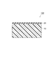
図1は、本発明の一実施形態に係る気体分離複合膜を模式的に示す断面図である。図1に示す気体分離複合膜100は、シート状の支持体10と、支持体10上に設けられた気体分離層20とを備えている。
(Gas separation composite membrane)
FIG. 1 is a cross-sectional view schematically showing a gas separation composite membrane according to an embodiment of the present invention. A gas
支持体10は、未延伸のエチレン系高分子を含む多孔質体からなる。エチレン系高分子は疎水性高分子であることから、気体分離層20を形成させる方法として、水面展開法等を採用するのに適している。また、フッ素樹脂やポリイミド樹脂等の他の疎水性高分子と比較して安価であるという利点も有する。
The
エチレン系高分子は、主としてポリエチレン骨格からなる重合体であり、例えば、ポリエチレン、ポリプロピレン、エチレン−アクリル酸共重合体、エチレン−αオレフィン共重合体、エチレン−不飽和エステル共重合体、エチレン−不飽和カルボン酸共重合体等が挙げられる。 The ethylene polymer is a polymer mainly composed of a polyethylene skeleton, for example, polyethylene, polypropylene, ethylene-acrylic acid copolymer, ethylene-α olefin copolymer, ethylene-unsaturated ester copolymer, ethylene-unsaturated copolymer. Examples thereof include saturated carboxylic acid copolymers.
これらのなかでも、結晶化度が高く、安価で、後述する方法(抽出法)で多孔質体を得るのに適している等の点で、ポリエチレンが好ましい。さらに、ポリエチレンは、結晶化度が90%以上であることが好ましく、95%以上であることがより好ましい。結晶化度が高いと、抽出法で用いる液剤を取り込み難い点や、耐熱性の点等で有利である。 Among these, polyethylene is preferable because it has a high degree of crystallinity, is inexpensive, and is suitable for obtaining a porous material by a method (extraction method) described later. Furthermore, the crystallinity of polyethylene is preferably 90% or more, and more preferably 95% or more. A high degree of crystallinity is advantageous in that it is difficult to take in the liquid used in the extraction method, heat resistance, and the like.
また、ポリエチレンとしては、高密度ポリエチレン(密度:0.95〜0.98g/cm3)が、短鎖の分岐が少なく、結晶化度が高い等の点で好ましい。さらに、高密度ポリエチレンのなかでも、分子量が100万以上である、いわゆる超高分子量ポリエチレンが、破断強度などの機械物性が高い点や、その融点である135℃以上においても流動して変形することがなく、耐熱性に優れている点等でより好ましい。 Further, as the polyethylene, high-density polyethylene (density: 0.95 to 0.98 g / cm 3 ) is preferable from the viewpoint of few short chain branches and high crystallinity. Furthermore, among high-density polyethylene, the so-called ultra-high molecular weight polyethylene having a molecular weight of 1 million or more has high mechanical properties such as breaking strength, and also flows and deforms even at its melting point of 135 ° C. or higher. It is more preferable in that it has excellent heat resistance.
未延伸のエチレン系高分子は、その製造される工程において延伸の操作を受けていないエチレン系高分子であり、この未延伸のエチレン系高分子を含む多孔質体からなる支持体は、水分の吸着及び脱水の過程における寸法安定性に優れる。通常、延伸法によるエチレン系高分子は、その機械強度を向上させること等を目的として、延伸倍率2倍程度以上で延伸されて製造されるが、本発明では、そのような延伸をされていないエチレン系高分子を用いる。 The unstretched ethylene-based polymer is an ethylene-based polymer that has not been subjected to a stretching operation in the production process, and the support made of a porous body containing the unstretched ethylene-based polymer has moisture content. Excellent dimensional stability in the process of adsorption and dehydration. Usually, an ethylene-based polymer obtained by a stretching method is produced by being stretched at a stretch ratio of about 2 times or more for the purpose of improving its mechanical strength, but in the present invention, such a stretch is not performed. Ethylene polymer is used.
一般に、エチレン系高分子のような結晶性の高分子からなる材料においては、溶融状態から冷却される際に、ラメラ晶といわれる結晶が生じる。材料が延伸されたときには、延伸される方向に沿って分子鎖が配向されるのに伴って、このラメラ晶が消失していく傾向にあるため、エチレン系高分子が未延伸であることは、このラメラ晶の大部分が残存していることから確認できる場合がある。 Generally, in a material made of a crystalline polymer such as an ethylene polymer, a crystal called a lamellar crystal is generated when cooled from a molten state. When the material is stretched, the lamellar crystals tend to disappear as the molecular chain is oriented along the stretched direction. It may be confirmed from the fact that most of the lamellar crystals remain.
なお、支持体10としての多孔質体は、未延伸のエチレン系高分子のみで構成されることが好ましいが、必要に応じて、可塑剤等の他の成分をさらに含んでいてもよい。
In addition, although the porous body as the
支持体10として用いる多孔質体は、20℃の水に10秒間浸漬され、さらに23±2℃で1時間放置されたときの収縮率が0〜10%であることが好ましく、0〜1%であることがより好ましい。ここで、この収縮率は、縦50〜150mm、横50〜150mm、厚さ0.05〜1.00mmのシート状の多孔質体を、上記の条件で処理したときに、その処理前後における縦又は横の長さの変化率(処理後/処理前)として定義される値とする。未延伸のエチレン系高分子を用いて、後述する方法によって得られる多孔質体の場合、通常、その収縮率は上記範囲内のものとなる。
The porous body used as the
また、支持体10は、孔壁に凝集性微粒子が付着した開気孔が形成された多孔質体からなることが、寸法安定性が特に優れる点等から、好ましい。
Further, it is preferable that the
支持体10の形状は、気体分離複合膜100においてはシート状であるが、この変形態様として、チューブ状、粒状、バルク状等であってもよい。ただ、空気を透過及び分離する際の簡便性を考慮すると、シート状であることが好ましい。支持体10がシート状である場合、その厚さは、20〜300μmあることが好ましく、50〜100μmであることがより好ましい。支持体10の厚さが20μm未満であると機械的強度が低下して取扱性が悪化する傾向があり、また、300μmを超えると空気の透過の際に抵抗が大きくなる傾向にある。
The shape of the
支持体10に用いる多孔質体においては、外気と通じている開気孔が形成されていることが好ましく、その平均孔径は、気体分離層20の厚さに対して3倍以下であることが好ましい。平均孔径がこれよりも大きい場合、気体分離複合膜100の使用時に気体分離層20が破れてしまいやすくなる傾向にある。本発明においては、気体分離層20の厚さが10〜1000nmであることが好ましいが、これに組み合わせる多孔質体における平均孔径は30〜3000nmであることが好ましく、30〜100nmであることがより好ましい。
In the porous body used for the
多孔質体の空隙率は、30体積%未満であると空気の透過の際に抵抗が大きくなる傾向にあり、80体積%を超えると機械的強度が低下して取扱性が悪化する傾向にあるため、30〜80体積%であることが好ましく、40〜60体積%であることがより好ましい。 When the porosity of the porous body is less than 30% by volume, the resistance tends to increase during the permeation of air, and when it exceeds 80% by volume, the mechanical strength tends to decrease and the handleability tends to deteriorate. Therefore, it is preferable that it is 30-80 volume%, and it is more preferable that it is 40-60 volume%.
以上述べたような多孔質体からなる支持体10は、例えば、後述するように、凝集性微粒子を用いた抽出法によって、好適に得ることができる。
The
気体分離層20は、ゴム状態又は溶融状態である相(以下、「ソフト相」という。)と、ガラス状態又は結晶状態である相(以下、「ハード相」という。)とに相分離した高分子、又は、上記一般式(1)で表されるオルガノポリシロキサン骨格と、上記一般式(2)で表されるイミド骨格とを含有する高分子(ポリイミドシロキサン)の薄膜からなる。ソフト相においてはゴム状態の領域と溶融状態の領域が混在してもよいし、ハード相においてはガラス状態の領域と結晶状態の領域とが混在してもよい。
The
上記の、ソフト相及びハード相に相分離している高分子においては、通常、これら二つの相からなるミクロ相分離構造が形成されている。ソフト相は、常温よりも低温の領域にてガラス転移現象を示し、常温では、ゴム状態または溶融状態となる相である。一方、ハード相は常温以下ではガラス転移せず、常温を超えた、より高温でガラス転移または溶融する相である。ソフト相を構成する成分とハード相を構成する成分とは、耐熱性の点等から、少なくとも一部が共有結合で結合されていることが好ましい。そのような高分子としては、例えば、主としてソフト相を構成する骨格(ソフトセグメント)と、主としてハード相を構成する骨格(ハードセグメント)とを含有する共重合体が好適である。 In the above-described polymer that is phase-separated into a soft phase and a hard phase, a microphase separation structure composed of these two phases is usually formed. The soft phase is a phase that exhibits a glass transition phenomenon in a region at a temperature lower than room temperature and is in a rubber state or a molten state at room temperature. On the other hand, the hard phase is a phase in which glass transition does not occur at room temperature or lower, and glass transition or melting occurs at a higher temperature exceeding room temperature. The component constituting the soft phase and the component constituting the hard phase are preferably at least partially bonded by a covalent bond from the viewpoint of heat resistance. As such a polymer, for example, a copolymer containing a skeleton (soft segment) mainly constituting a soft phase and a skeleton (hard segment) mainly constituting a hard phase is suitable.
高分子がこのようなソフト相及びハード相に相分離していることは、例えば、動的粘弾性測定を行ったときに、常温以下のガラス転移点(第一の転移点)と、高温でのガラス転移点または溶融点(第二の転移点)とが観測されることで確認できる。 The fact that the polymer is phase-separated into such a soft phase and a hard phase means that, for example, when a dynamic viscoelasticity measurement is performed, a glass transition point (first transition point) below normal temperature and a high temperature. This can be confirmed by observing the glass transition point or melting point (second transition point).
この第一の転移点は通常20℃以下であり、−20℃以下であることがより好ましい。一方、第二の転移点は通常100℃以上であり、130℃以上であることがより好ましい。なお、これら転移点は、測定周波数1Hz、昇温速度10℃/分の動的粘弾性測定で測定される値とする。 This first transition point is usually 20 ° C. or lower, and more preferably −20 ° C. or lower. On the other hand, the second transition point is usually 100 ° C. or higher, and more preferably 130 ° C. or higher. These transition points are values measured by dynamic viscoelasticity measurement at a measurement frequency of 1 Hz and a heating rate of 10 ° C./min.
気体分離層20の一部が、支持体10から剥がれて浮き上がってしまう現象(浮き上がり)の発生を抑制する効果は、一つには、上記のような高分子の薄膜が、伸びやすい性質を有していることに起因していると考えられる。
One of the effects of suppressing the phenomenon that a part of the
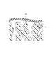
支持体10上に気体分離層20を形成させたとき、支持体を構成するエチレン系高分子11と気体分離層20との間に抱き込まれた空気によって、例えば、図2に示すように空隙30が形成され、その部分の気体分離層20が浮き上がった状態となることがある。このような状態となった場合でも、気体分離層20が伸びやすい性質を有していれば、経時的に空隙30近傍の気体分離層20がエチレン系高分子11表面の凹凸に沿うように変形して、数10秒〜数分のうちには空隙30が消失し、結果的に浮き上がりもなくなると考えられる。
When the
浮き上がり抑制の効果をより高めるために、気体分離層20としての薄膜を構成する高分子は、その伸びが80%以上であることが好ましく、500%以上であることがより好ましい。ただし、この伸びは、薄膜を構成する高分子からなる試験片について、JIS K7311に規定される方法におって引張試験を行って得られる値とする。本発明者らの検討の結果、このパラメータを指標とすることが、エチレン系高分子11で構成される支持体10と、気体分離層20との密着性の指標として有効であることが明かとなった。
In order to further enhance the effect of suppressing lifting, the polymer constituting the thin film as the
伸びが80%未満であると、図2に示すように空隙30が形成された状態が長期的に維持される傾向にある。この場合、気体分離複合膜100に僅かな外力が加わったときでも、空隙30を形成している部分の気体分離層が裂けてしまう場合がある。一方、伸びが500%を超える高分子の場合は、空隙30が形成されたとしても、極めて短時間で消失する。
When the elongation is less than 80%, the state in which the
また、伸びが80%以上の薄膜の場合、空隙30が形成された部分に、圧縮エアーを吹き付けると、空隙30中の空気が支持体10の開気孔を通じて抜けるので、空隙30が消失するまでの時間を短縮することもできる。この方法は、伸びが80%以上の薄膜の場合はほぼ問題なく行うことができるが、薄膜の伸びが80%未満である場合にこの方法を採用すると、薄膜が空気圧で破れやすくなる傾向にある。
Further, in the case of a thin film having an elongation of 80% or more, when compressed air is blown onto the portion where the
気体分離層20の厚さは10〜1000nmであることが好ましく、50〜200nmであることがより好ましい。厚さが1000nmを超えると気体透過性が充分でなくなる傾向にあり、10nm未満ではその取り扱い性が低下する傾向にある。なお、気体分離層20の厚さは、例えば、気体分離層20の一部を支持体10上から除去し、気体分離層20が残っている場所と除去された場所との段差を、AFM等で測定することによって定量できる。
The thickness of the
上記の高分子において、ソフト相を主として構成する骨格(ソフトセグメント)としては、エチレン−ブチレン共重合体、エチレン−スチレン共重合体、アクリル酸エステル系重合体、オルガノポリシロキサンなどからなる骨格が挙げられる。これらのなかでも、気体透過性の点から、オルガノポリシロキサン骨格が好ましい。 In the above polymer, examples of the skeleton (soft segment) mainly constituting the soft phase include a skeleton made of an ethylene-butylene copolymer, an ethylene-styrene copolymer, an acrylate polymer, an organopolysiloxane, and the like. It is done. Among these, an organopolysiloxane skeleton is preferable from the viewpoint of gas permeability.
ハード相を主として構成する骨格(ハードセグメント)としては、ポリエチレンなどの結晶性の重合体、又は、ポリイミド、ポリカーボネートなどの非晶質の剛直な骨格が挙げられる。これらのなかでも、耐熱性等の点から、ポリイミドが好ましい。 Examples of the skeleton (hard segment) mainly constituting the hard phase include a crystalline polymer such as polyethylene, or an amorphous rigid skeleton such as polyimide and polycarbonate. Among these, polyimide is preferable from the viewpoint of heat resistance and the like.
ポリイミドシロキサンにおいては、通常、主としてオルガノポリシロキサン骨格からなるソフト相と、主としてイミド骨格からなるハード相とからなる、ミクロ相分離構造が形成されている。気体分離層20は、気体透過性、酸素富化、耐熱性、機械強度等の点から、このポリイミドシロキサンを含む薄膜からなることが特に好ましい。
In polyimidesiloxane, a microphase-separated structure is generally formed, which is composed of a soft phase mainly composed of an organopolysiloxane skeleton and a hard phase mainly composed of an imide skeleton. The
ポリイミドシロキサンとしては、すでに上に挙げた、下記一般式(1)で表されるオルガノポリシロキサン骨格と、下記一般式(2)で表されるイミド骨格とを含有するものが好適である。なお、オルガノポリシロキサン骨格とイミド骨格とは、互いにブロック状に結合していても良く、ランダムに結合していても良い。 As the polyimidesiloxane, those containing the above-mentioned organopolysiloxane skeleton represented by the following general formula (1) and the imide skeleton represented by the following general formula (2) are preferable. The organopolysiloxane skeleton and the imide skeleton may be bonded to each other in a block shape or may be bonded at random.
上記のポリイミドシロキサンにおいて、ソフトセグメントであるオルガノポリシロキサン骨格の含有量は、ポリイミドシロキサン全体を基準として、35質量%以上であることが好ましく、35〜97質量%であることがより好ましく、40〜97質量%であることがさらに好ましい。オルガノポリシロキサンの含有量が大きいと、ポリイミドシロキサンの機械特性はエラストマー的な傾向が強くなり、柔軟性と伸縮性に富むものとなる。この含有量を35質量%以上とすることで、気体分離層20が特に伸びやすくなり、35質量%未満の場合と比較して、支持体10との密着性がより良好になる。また、この含有量が97質量%を超えると耐熱性や機械強度が低下する傾向にある。
In the above-described polyimidesiloxane, the content of the organopolysiloxane skeleton that is a soft segment is preferably 35% by mass or more, more preferably 35 to 97% by mass, based on the entire polyimidesiloxane, and 40 to 40%. More preferably, it is 97 mass%. When the content of the organopolysiloxane is large, the mechanical properties of the polyimidesiloxane are more likely to be elastomeric and rich in flexibility and stretchability. By making this content 35% by mass or more, the
このポリイミドシロキサンは、例えば、下記一般式(3)で表される骨格からなる繰り返し単位(上記一般式(1)で表されるオルガノポリシロキサン骨格を含んでいる)と、上記一般式(2)で表されるイミド骨格からなる繰り返し単位とを有するものであってもよい。 This polyimidesiloxane is, for example, a repeating unit composed of a skeleton represented by the following general formula (3) (including an organopolysiloxane skeleton represented by the above general formula (1)) and the above general formula (2). And a repeating unit composed of an imide skeleton represented by
また、ポリイミドシロキサンは、下記一般式(4)で表される繰り返し単位を有するものであってもよい。なお、式(4)のnは正の整数を示す。 Further, the polyimidesiloxane may have a repeating unit represented by the following general formula (4). In the formula (4), n represents a positive integer.
上記一般式(1)〜(4)におけるR1、R2、R3及びR4は、それぞれ独立に1価の脂肪族基又は1価の芳香族基を示し、これらはフッ素原子で置換されていてもよい。1価の脂肪族基としては、1価の飽和炭化水素基又は1価の不飽和炭化水素基が挙げられる。1価の飽和炭化水素基としては炭素数1〜22のアルキル基が挙げられ、例えば、メチル基、エチル基、プロピル基が例示できる。1価の不飽和炭化水素基としては炭素数2〜22のアルケニル基が挙げられ、例えば、ビニル基、プロペニル基が例示できる。1価の芳香族基としては、炭素数6〜24のアリール基、アラルキル基等が例示できる。R1、R2、R3及びR4としては、特に、メチル基又はフェニル基が好ましい。また、rは正の整数を示し、10〜10,000の整数であることが好ましい。 R 1 , R 2 , R 3 and R 4 in the general formulas (1) to (4) each independently represent a monovalent aliphatic group or a monovalent aromatic group, and these are substituted with a fluorine atom. It may be. Examples of the monovalent aliphatic group include a monovalent saturated hydrocarbon group and a monovalent unsaturated hydrocarbon group. Examples of the monovalent saturated hydrocarbon group include an alkyl group having 1 to 22 carbon atoms, and examples thereof include a methyl group, an ethyl group, and a propyl group. Examples of the monovalent unsaturated hydrocarbon group include alkenyl groups having 2 to 22 carbon atoms, and examples thereof include a vinyl group and a propenyl group. Examples of the monovalent aromatic group include an aryl group having 6 to 24 carbon atoms and an aralkyl group. As R 1 , R 2 , R 3 and R 4 , a methyl group or a phenyl group is particularly preferable. R represents a positive integer and is preferably an integer of 10 to 10,000.
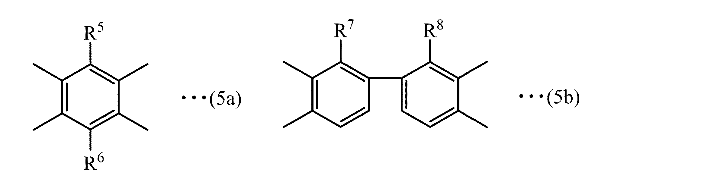
また、上記一般式(1)〜(4)におけるXは、4価の芳香族基を示し、下記一般式(5a)〜(5k)、(5m)、(5n)、(5p)及び(5q)でそれぞれ表される4価の芳香族基であることが好ましい。 X in the general formulas (1) to (4) represents a tetravalent aromatic group, and the following general formulas (5a) to (5k), (5m), (5n), (5p) and (5q) It is preferable that it is a tetravalent aromatic group represented by each.
上記式(5a)〜(5k)、(5m)、(5n)、(5p)及び(5q)において、R5及びR6は、それぞれ独立に水素原子、メチル基、トリフルオロメチル基又はフェニル基を示し、R7及びR8はそれぞれ独立に水素原子、トリフルオロメチル基又はフェニル基を示す。sは正の整数を示し、好ましくは1〜20の整数である。また、R9及びR10は、それぞれ独立にトリフルオロメチル基又はフェニル基を示し、Aは、エチレン基又は下記一般式(6a)〜(6c)で表される2価の芳香族基を示す。 In the above formulas (5a) to (5k), (5m), (5n), (5p) and (5q), R 5 and R 6 are each independently a hydrogen atom, a methyl group, a trifluoromethyl group or a phenyl group. R 7 and R 8 each independently represents a hydrogen atom, a trifluoromethyl group or a phenyl group. s shows a positive integer, Preferably it is an integer of 1-20. R 9 and R 10 each independently represent a trifluoromethyl group or a phenyl group, and A represents an ethylene group or a divalent aromatic group represented by the following general formulas (6a) to (6c). .
また、上記一般式(1)〜(4)において、Z1及びZ2は、それぞれ独立に2価の脂肪族基又は2価の芳香族基を示し、これらの基はフッ素原子で置換されていてもよい。2価の脂肪族基としては、2価の飽和炭化水素基又は2価の不飽和炭化水素基が挙げられる。2価の飽和炭化水素基としては炭素数1〜22のアルキレン基が挙げられ、例えば、メチレン基、エチレン基、プロピレン基が例示できる。2価の不飽和炭化水素基としては、炭素数2〜22の不飽和炭素水素基が挙げられ、例えば、ビニレン基、プロペニレン基、末端に不飽和二重結合を有するアルキレン基が例示できる。2価の芳香族基としては炭素数6〜24のフェニレン基、アルキル基で置換されたフェニレン基、アラルキレン基等が例示できる。Z1及びZ2としては、特に、プロピレン基、フェニレン基、アラルキレン基が好ましい。 In the general formulas (1) to (4), Z 1 and Z 2 each independently represent a divalent aliphatic group or a divalent aromatic group, and these groups are substituted with a fluorine atom. May be. Examples of the divalent aliphatic group include a divalent saturated hydrocarbon group or a divalent unsaturated hydrocarbon group. As a bivalent saturated hydrocarbon group, a C1-C22 alkylene group is mentioned, For example, a methylene group, ethylene group, and a propylene group can be illustrated. As a bivalent unsaturated hydrocarbon group, a C2-C22 unsaturated carbon group is mentioned, For example, the alkylene group which has an unsaturated double bond at the terminal can be illustrated, for example, vinylene group, propenylene group. Examples of the divalent aromatic group include a phenylene group having 6 to 24 carbon atoms, a phenylene group substituted with an alkyl group, and an aralkylene group. Z 1 and Z 2 are particularly preferably a propylene group, a phenylene group, and an aralkylene group.
また、上記一般式(1)〜(4)おけるYは、2価の脂肪族基又は2価の芳香族基を示し、下記一般式(7)又は下記一般式(8)で表される2価の芳香族基であることが好ましい。式(8)において、tは正の整数を示し、1〜22の整数であることが好ましい。 Y in the general formulas (1) to (4) represents a divalent aliphatic group or a divalent aromatic group, and is represented by the following general formula (7) or the following general formula (8). A valent aromatic group is preferred. In the formula (8), t represents a positive integer and is preferably an integer of 1 to 22.
気体分離層20に用いるポリイミドシロキサンは、ゲルパーミエーションクロマトグラフィー(GPC)による標準ポリスチレン換算の重量平均分子量(Mw)が1,000〜100,000であることが好ましく、5,000〜50,000であることがより好ましい。
The polyimidesiloxane used in the
上記一般式(1)で表される繰り返し単位及び上記一般式(2)で表される繰り返し単位を有するポリイミドシロキサンは、下記一般式(9)で表される、末端にアミノ基を有するオルガノポリシロキサン(以下、「シロキサンジアミン」という)、及び、下記一般式(10)で表されるシロキサンを含まないジアミンからなるジアミン混合物と、多塩基酸の二無水物とを脱水縮合反応させて得ることができる。この脱水縮合反応は、従来公知の方法を採用して行うことができる。なお、以下の説明における化学式中の符号は、上記化学式における内容と同様の構造を示す。 The polyimidesiloxane having the repeating unit represented by the general formula (1) and the repeating unit represented by the general formula (2) is an organopolysiloxane having an amino group at the terminal represented by the following general formula (9). Obtained by a dehydration condensation reaction of a diamine (hereinafter referred to as “siloxane diamine”) and a diamine mixture not containing a siloxane represented by the following general formula (10) and a polybasic acid dianhydride. Can do. This dehydration condensation reaction can be carried out by employing a conventionally known method. In addition, the code | symbol in chemical formula in the following description shows the structure similar to the content in the said chemical formula.
多塩基酸の二酸無水物としては、下記一般式(11)で表されるテトラカルボン酸の二無水物が好適に使用される。 As the dianhydride of polybasic acid, a dianhydride of tetracarboxylic acid represented by the following general formula (11) is preferably used.
上記一般式(9)で表されるシロキサンジアミンの市販品として入手できるものとしては、X−22−9409、X−22−1660B、X−22−161AS、X−22−161A、X−22−161B(以上、信越化学工業(株)製)等が挙げられる。これらは、単独で又は2種類以上を組み合わせて使用することができる。 As what can be obtained as a commercial item of the siloxane diamine represented by the general formula (9), X-22-9409, X-22-1660B, X-22-161AS, X-22-161A, X-22- 161B (manufactured by Shin-Etsu Chemical Co., Ltd.) and the like. These can be used alone or in combination of two or more.
上記一般式(10)で表されるジアミンとしては、芳香族ジアミンが好適に使用される。芳香族ジアミンとしては、例えば、下記式(12)又は下記一般式(13)で表される化合物が挙げられる。 As the diamine represented by the general formula (10), an aromatic diamine is preferably used. Examples of the aromatic diamine include compounds represented by the following formula (12) or the following general formula (13).
上記一般式(13)で表される芳香族ジアミンとしては、4,4´−ジアミノフェノキシメタン、1,2−ビス(4−アミノフェノキシ)エタン、1,3−ビス(4−アミノフェノキシ)プロパン、1,4−ビス(4−アミノフェノキシ)ブタン、1,5−ビス(4−アミノフェノキシ)ペンタン、1,6−ビス(4−アミノフェノキシ)ヘキサン、1,7−ビス(4−アミノフェノキシ)ヘプタン、1,8−ビス(4−アミノフェノキシ)オクタン、1,9−ビス(4−アミノフェノキシ)ノナン、1,10−ビス(4−アミノフェノキシ)デカン、1,11−ビス(4−アミノフェノキシ)ウンデカン、1,12−ビス(4−アミノフェノキシ)ドデカン、1,13−ビス(4−アミノフェノキシ)トリデカン、1,14−ビス(4−アミノフェノキシ)テトラデカン、1,15−ビス(4−アミノフェノキシ)ペンタデカン、1,16−ビス(4−アミノフェノキシ)ヘキサデカン、1,17−ビス(4−アミノフェノキシ)ヘプタデカン、1,18−ビス(4−アミノフェノキシ)オクタデカン、1,19−ビス(4−アミノフェノキシ)ノナデカン、1,20−ビス(4−アミノフェノキシ)イコサン等が挙げられる。これらは、単独又は2種類以上を組み合わせて使用することができる。 Examples of the aromatic diamine represented by the general formula (13) include 4,4′-diaminophenoxymethane, 1,2-bis (4-aminophenoxy) ethane, and 1,3-bis (4-aminophenoxy) propane. 1,4-bis (4-aminophenoxy) butane, 1,5-bis (4-aminophenoxy) pentane, 1,6-bis (4-aminophenoxy) hexane, 1,7-bis (4-aminophenoxy) ) Heptane, 1,8-bis (4-aminophenoxy) octane, 1,9-bis (4-aminophenoxy) nonane, 1,10-bis (4-aminophenoxy) decane, 1,11-bis (4- Aminophenoxy) undecane, 1,12-bis (4-aminophenoxy) dodecane, 1,13-bis (4-aminophenoxy) tridecane, 1,14-bis (4-a Nophenoxy) tetradecane, 1,15-bis (4-aminophenoxy) pentadecane, 1,16-bis (4-aminophenoxy) hexadecane, 1,17-bis (4-aminophenoxy) heptadecane, 1,18-bis ( 4-aminophenoxy) octadecane, 1,19-bis (4-aminophenoxy) nonadecane, 1,20-bis (4-aminophenoxy) icosane and the like. These can be used alone or in combination of two or more.
上記一般式(11)で表されるテトラカルボン酸の二酸無水物としては、例えば、ピロメリット酸二無水物、メチルピロメリット酸二無水物、トリフルオロメチルピロメリット酸二無水物、フェニルピロメリット酸二無水物、ジフェニルピロメリット酸二無水物、3,3´,4,4´−ビフェニルテトラカルボン酸二無水物、2,2´−ジフェニル−3,3´,4,4´−ビフェニルテトラカルボン酸二無水物、2,2´−ジトリフルオロメチル−3,3´,4,4´−ビフェニルテトラカルボン酸二無水物、2,2´,3,3´−ビフェニルテトラカルボン酸二無水物、3,3´,4,4´−ベンゾフェノンテトラカルボン酸二無水物、2,2´,3,3´−ベンゾフェノンテトラカルボン酸二無水物、3,3´,4,4´−ジフェニルスルフォンテトラカルボン酸二無水物、3,3´,4,4´−ジフェニルヘキサフルオロイソプロピリデンテトラカルボン酸二無水物、1,1´−ビス(3,4−ジカルボキシフェニル)−1−フェニル−2,2,2−トリフルオロエタン二無水物、3,3´,4,4´−ジフェニルイソプロピリデンテトラカルボン酸二無水物、3,3´,4,4´−ジフェニルメタンテトラカルボン酸二無水物、3,3´,4,4´−ベンゾスルフィドテトラカルボン酸二無水物、2,2´,3,3´−ベンゾスルフィドテトラカルボン酸二無水物、3,3´,4,4´−ジフェニルアミンテトラカルボン酸二無水物、3,3´,4,4´−ジフェニルアミドテトラカルボン酸二無水物、2,2−ビス(3,4−ジカルボキシフェノキシ)ジフェニルプロパン二無水物、ビス(3,4−ジカルボキシフェノキシ)ベンゼン二無水物、ビス(3,4−ジカルボキシフェノキシ)エタン二無水物、ビス(3,4−ジカルボキシフェニル)ヘキサフロロプロパン二無水物、4,4´−ビス(3,4−ジカルボキシフェノキシ)ジフェニルスルフィド二無水物、4,4´−オキシジフタル酸二無水物、ビス(3,4−ジカルボキシフェニル)フォスフィンオキサイド二無水物等が挙げられる。これらは、単独で又は2種類以上を組み合わせて使用することができる。 Examples of the tetracarboxylic dianhydride represented by the general formula (11) include pyromellitic dianhydride, methyl pyromellitic dianhydride, trifluoromethylpyromellitic dianhydride, phenyl pyro Mellitic acid dianhydride, diphenylpyromellitic dianhydride, 3,3 ′, 4,4′-biphenyltetracarboxylic dianhydride, 2,2′-diphenyl-3,3 ′, 4,4′-biphenyl Tetracarboxylic dianhydride, 2,2'-ditrifluoromethyl-3,3 ', 4,4'-biphenyltetracarboxylic dianhydride, 2,2', 3,3'-biphenyltetracarboxylic dianhydride 3,3 ′, 4,4′-benzophenone tetracarboxylic dianhydride, 2,2 ′, 3,3′-benzophenone tetracarboxylic dianhydride, 3,3 ′, 4,4′-diphenylsulfate Fonte Lacarboxylic acid dianhydride, 3,3 ′, 4,4′-diphenylhexafluoroisopropylidenetetracarboxylic dianhydride, 1,1′-bis (3,4-dicarboxyphenyl) -1-phenyl-2, 2,2-trifluoroethane dianhydride, 3,3 ′, 4,4′-diphenylisopropylidenetetracarboxylic dianhydride, 3,3 ′, 4,4′-diphenylmethanetetracarboxylic dianhydride, 3 , 3 ′, 4,4′-benzosulfide tetracarboxylic dianhydride, 2,2 ′, 3,3′-benzosulfide tetracarboxylic dianhydride, 3,3 ′, 4,4′-diphenylamine tetracarboxylic Acid dianhydride, 3,3 ′, 4,4′-diphenylamide tetracarboxylic dianhydride, 2,2-bis (3,4-dicarboxyphenoxy) diphenylpropane dianhydride, bis (3 4-dicarboxyphenoxy) benzene dianhydride, bis (3,4-dicarboxyphenoxy) ethane dianhydride, bis (3,4-dicarboxyphenyl) hexafluoropropane dianhydride, 4,4′-bis ( 3,4-dicarboxyphenoxy) diphenyl sulfide dianhydride, 4,4′-oxydiphthalic dianhydride, bis (3,4-dicarboxyphenyl) phosphine oxide dianhydride, and the like. These can be used alone or in combination of two or more.
上記一般式(4)で表される繰り返し単位を有するポリイミドシロキサンは、末端に酸無水物基を有するポリイミドに、上記一般式(9)で表されるシロキサンジアミンを反応させて得ることができる。 The polyimidesiloxane having the repeating unit represented by the general formula (4) can be obtained by reacting the siloxane diamine represented by the general formula (9) with a polyimide having an acid anhydride group at the terminal.
なお、気体分離層20としての薄膜は、上述したようなポリイミドシロキサン等の高分子のみで構成されていることが好ましいが、必要に応じて、可塑剤、無機粒子などの他の成分をさらに含んでもよい。
The thin film as the
(気体分離複合膜の製造方法)
以上説明したような気体分離複合膜100を得るための好適な製造方法について、支持体10として用いる多孔質体の製造方法、支持体10の上に気体分離層20を形成させる方法の順に、以下に詳細に説明する。
(Method for producing gas separation composite membrane)
About the suitable manufacturing method for obtaining the gas
支持体10として用いる多孔質体は、凝集性微粒子と、液剤と、未延伸のエチレン系高分子とを混合した混合物から液剤を除去する方法によって、好適に得ることができる。凝集性微粒子を用いることにより、液剤を除去する際の多孔質体全体の体積変化を小さくすることができ、得られる多孔質体の寸法安定性が特に優れたものとなる。
The porous body used as the
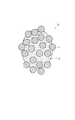
この方法では、まず、凝集性微粒子と、液剤と、未延伸のエチレン系高分子とを混合した混合物を得る。このとき、凝集性微粒子に液剤を付着させた、図4に示すような付着体を別途調製し、この付着体とエチレン系高分子とを混合してもよいし、凝集性微粒子、液剤及びエチレン系高分子を同時に混練機に投入する等して混合してもよい。 In this method, first, a mixture in which cohesive fine particles, a liquid agent, and an unstretched ethylene polymer are mixed is obtained. At this time, an adhering body as shown in FIG. 4 in which a liquid agent is adhered to the aggregating fine particles may be separately prepared, and the adhering body and the ethylene polymer may be mixed, or the aggregating fine particles, the liquid agent, and ethylene may be mixed. The high molecular weight polymer may be mixed by, for example, charging it into a kneader.
混合においては、凝集性微粒子1及び液剤2を均一に分散させるために、押出し機、ニーダーなどの混練装置により、エチレン系高分子の融点よりも高い温度で混練することが好ましい。通常、混練の履歴によって粒子の凝集状態は随時変化するが、トルク出力と混錬時間との積や、混練における樹脂温度を制御することで、再現性よく混錬を行うことができる。
In the mixing, in order to uniformly disperse the coherent
また、混合物が含有する液剤の量によって、得られる多孔質体の空隙率を制御することができる。得られる多孔質体の空隙率を好ましい範囲とするために、液剤の量は混合物全体を基準として30〜80体積%であることが好ましく、40〜60体積%であることがより好ましい。 Moreover, the porosity of the obtained porous body can be controlled by the amount of the liquid agent contained in the mixture. In order to make the porosity of the obtained porous body into a preferable range, the amount of the liquid agent is preferably 30 to 80% by volume, more preferably 40 to 60% by volume based on the whole mixture.
混練された混合物を、一旦、ペレット状、ベール状、ベルト状等に加工し、その後、押出し機、カレンダー、ロール、ベルト等によってシート状等に成形して、多孔質体の前駆体とすることが好ましい。押出し機を用いた場合には、混練及び成形を一括に行うことができる。なお、混錬に用いる装置等は、上記以外のものであってもよい。 The kneaded mixture is once processed into pellets, veils, belts, etc., and then formed into sheets by an extruder, calender, roll, belt, etc., and used as a precursor of a porous body. Is preferred. When an extruder is used, kneading and molding can be performed at once. The apparatus used for kneading may be other than the above.
図5は、混錬及び成形を経た後の、上記混合物からなるシート状の前駆体10aを模式的に示す断面図である。前駆体10aにおいては、凝集性微粒子1の凝集体に液剤2が取り込まれて形成された領域が、エチレン系高分子11中に分散している。混錬の際にエチレン系高分子が溶融している段階では、液剤2がエチレン系高分子にも取り込まれるが、成形後、混合物が冷却され、エチレン系高分子の結晶(ラメラ晶)が成長するのに伴って、液剤2がエチレン系高分子から吐き出され、再び凝集性微粒子1の凝集体に取り込まれて、図5に示す前駆体10aのような状態となる。
FIG. 5 is a cross-sectional view schematically showing a sheet-
図4は、混合のとき用いる付着体を模式的に示した断面図である。図4に示す付着体5においては、凝集性微粒子1の一次粒子の集合体(以下、「凝集体」という。)の隙間に染み込むようにして、液剤2が付着している。凝集性微粒子1は凝集体を形成しているために、液剤2を付着させることで図2に示すような付着体5を容易に得ることができる。付着体5は、例えば、凝集性微粒子1と液剤2とを混合したものを、加圧ニーダー等を用いて混錬することで得られる。
FIG. 4 is a cross-sectional view schematically showing an adherent used for mixing. In the adhering
凝集性微粒子1としては、ケッチェンブラック、シリカ、合成湿式炭酸カルシウム、アクリル架橋粒子などが挙げられるが、凝集性が高く、エチレン系高分子との混合物においても液剤を保持しやすい性質を有する点で、シリカが好ましい。このシリカとは、酸化ケイ素(珪酸)を指し、石英などの天然の無水珪酸を粉砕して得られるものや、湿式シリカや霧煙質シリカなどの合成シリカ等がある。これらのなかでも、凝集性の点で、凝集性微粒子1は合成シリカであることが好ましい。
Examples of the aggregating
凝集性微粒子の凝集力については、その油等の吸収量によって定量できることが一般に知られており、例えば、ASTM D2414−93においては、DBP(ジブチルフタレート)の吸収量(DBP吸油量)によって、微粒子の凝集性を定量する方法が規定されている。凝集性微粒子1については、上記のDBP吸油量が、50[cm3/100g]以上であることが好ましく、200〜400[cm3/100g]であることがより好ましい。DBP吸油量が50[cm3/100g]未満であると液剤の保持力が不足する傾向にある。
It is generally known that the cohesive force of the cohesive fine particles can be quantified by the absorption amount of the oil or the like. For example, in ASTM D2414-93, the fine particle is determined by the absorption amount (DBP oil absorption amount) of DBP (dibutyl phthalate). A method for quantifying the cohesiveness of the water is defined. For cohesive
また、凝集性微粒子1の一次粒子径は、1.0μm以下であることが望ましく、0.05μm以下であることがより好ましい。一次粒子径が1.0μmを超えると凝集力が低下する傾向にある。凝集性微粒子1からなる凝集体を粒子とみなしたときのその粒径は、100μm以下であることが好ましく、10μm以下であることがより好ましい。この粒径が100μmを超えると、得られる多孔質体に形成される細孔の孔径が大きくなり、気体分離層20の破れを招きやすくなる傾向にある。
Further, the primary particle diameter of the aggregating
付着体5における、凝集性微粒子1の含有量は、その種類に応じて適宜決定すればよいが、例えば、凝集性微粒子1のDBP吸油量が200〜400[cm3/100g]である場合には、液剤2に対する重量比で1/5〜1/2であることが好ましい。
In
液剤2としては、凝集性微粒子1の凝集体が効率的に吸収できる液体を用いることが好ましい。具体的には、パラフィン系オイル、フタル酸エステル等が好適である。
As the
パラフィン系オイルとしては、前駆体10aからの除去の効率を高めるために、分子量が500以下であるものが好ましく10〜100であるものがより好ましい。また、その粘度は1000mPa・s以下であることが好ましく、10〜100mPa・sであることがより好ましい。
The paraffinic oil preferably has a molecular weight of 500 or less and more preferably 10 to 100 in order to increase the efficiency of removal from the
フタル酸エステルは、ジオクチルフタレート(DOP)、ジイソノリルフタレート(DINP)などの、フタル酸とアルコールとのジエステルである。このアルコールはその炭素数が3〜12の炭素数であることが好ましく、7〜10の炭素数であることがより好ましい。炭素数が3以下であると沸点が低く、混合や成形時における揮発により失われてしまいやすい傾向にあり、炭素数が18を超えると常温で流動性を失って、凝集性微粒子1に付着させるのが困難となってしまう傾向にある。
Phthalates are diesters of phthalic acid and alcohol, such as dioctyl phthalate (DOP) and diisonolyl phthalate (DINP). The alcohol preferably has 3 to 12 carbon atoms, more preferably 7 to 10 carbon atoms. When the number of carbon atoms is 3 or less, the boiling point is low and tends to be lost due to volatilization during mixing or molding. When the number of carbon atoms exceeds 18, the fluidity is lost at room temperature and is attached to the coherent
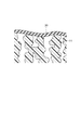
次に、前駆体10aから、液剤2を除去することにより細孔が形成され、図6に示されるような、多孔質体からなるシート状の支持体10が得られる。図6は、孔壁に凝集性微粒子1が付着した開気孔が形成されている支持体10を、模式的に示した断面図である。
Next, pores are formed by removing the
液剤2の除去は、抽出溶媒によって液剤2を抽出することによって、好適に行うことができる。抽出は、例えば、前駆体10aを、トルエン、ヘキサン、キシレン、各種アルコール類、ゴム揮発油、熱水、沸騰水などの抽出溶媒に浸漬して行う。抽出を行う条件は、用いる抽出溶媒等に応じて適宜決定すればよい。浸漬後、多孔質体に付着している抽出溶媒を除去(乾燥)して、支持体10を得る。この乾燥は、自然乾燥でもよいし、加熱や送風による強制乾燥でもよい。
The removal of the
以上のようにして得られる支持体10の上に、気体分離層20を積層することにより、気体分離複合膜100が得られる。気体分離層20の薄膜を形成させる方法としては、高分子を水面上に展開させる、水面展開法が好適である。
The gas
この水面展開法では、高分子を溶剤に溶解させた高分子溶液を水面に滴下して、水面においてこの高分子を溶液として展開させることにより、薄膜を形成させる。滴下された高分子溶液は、表面張力によってただちに水面上に展開し、展開とほぼ同時に溶剤が蒸発して、高分子の薄膜が形成される。続いて、形成された薄膜を、水没させておいた支持体10で掬い取ってその表面に接触させると、薄膜が支持体10に張り付いて両者が一体化される。さらに、支持体10及び薄膜(気体分離層20)に付着した水分を除去することによって、気体分離複合膜100を得ることができる。
In this water surface development method, a polymer solution in which a polymer is dissolved in a solvent is dropped onto the water surface, and the polymer is developed as a solution on the water surface to form a thin film. The dropped polymer solution immediately develops on the water surface due to surface tension, and the solvent evaporates almost simultaneously with the development to form a polymer thin film. Subsequently, when the formed thin film is scooped with the
上記高分子溶液に用いる溶媒は、気体分離層20を構成する高分子の溶解性が良好なものから選択されることが好ましい。例えば、高分子がポリイミドシロキサンである場合には、トルエン、メチルエチルケトン、N−メチルピロリドン等の有機溶剤が好ましい。この溶液の高分子の濃度は、高分子溶液全体を基準として5〜30質量%であることが好ましい。
The solvent used in the polymer solution is preferably selected from those having good solubility of the polymer constituting the
高分子溶液を水面に滴下するには、ディスペンサー、注射器、スポイトなどを好適に用いることができる。あるいは、高分子溶液の供給装置を水中に設置して、溶液の浮力により水面に浮上させて展開させてもよい。 In order to drop the polymer solution onto the water surface, a dispenser, a syringe, a dropper, or the like can be preferably used. Alternatively, the polymer solution supply device may be installed in water and floated on the surface of the water by the buoyancy of the solution.
支持体10が長尺のシートである場合、支持体10を、繰り入れ装置によって送り出して一旦水中に通し、水面に形成された薄膜を掬い取らせつつ、巻き取り装置で順次巻き取っていくといった、連続プロセスを採用することもできる。このような連続プロセスを採用する場合、支持体の送り速度に合わせて溶液の供給量を調節するのがよい。また、支持体10への薄膜の積層を複数回繰り返して、気体分離層20の厚さを調節することもできる。
In the case where the
以下に本発明の内容を実施例によりさらに詳細に説明するが、本発明はこれら実施例に限定されるものではない。 The content of the present invention will be described in more detail with reference to the following examples, but the present invention is not limited to these examples.
(実施例1)
<多孔質体Aの作製>
パラフィンオイル(ルーカント360、商品名、三井化学株式会社製)100重量部と、平均粒径が16nmの一次粒子が凝集してなる平均粒径9μmの湿式シリカ粒子(ニップシールLP、商品名、日本シリカ工業株式会社製)50重量部とを混合したものを、室温にて加圧ニーダーで混錬し、凝集性微粒子であるシリカ粒子の凝集体に、液剤であるパラフィンオイルが付着した付着体を得た。
次に、約160℃に温度調節した二本ロールを用いて、分子量が300万程度である高密度超高分子量ポリエチレン(ハイゼックスミリオン220、商品名、分子量約300万、三井石油化学工業株式会社製)100重量部と、上記で得た付着体300重量部とを混合し、これを混錬して、白色の混合物からなり、厚さが約0.2mmのシート状の前駆体を得た。この前駆体においては、超高分子量ポリエチレン100重量部、パラフィンオイル200重量部、シリカ粒子100重量部の割合でこれらが混合されており、前駆体全体の体積に対して約44.5体積%をパラフィンオイルが占めていた。
(Example 1)
<Preparation of porous body A>
100 parts by weight of paraffin oil (Lucant 360, trade name, manufactured by Mitsui Chemicals) and wet silica particles having an average particle diameter of 9 μm formed by agglomeration of primary particles having an average particle diameter of 16 nm (Nipseal LP, trade name, Nippon Silica) (Made by Kogyo Co., Ltd.) A mixture of 50 parts by weight was kneaded with a pressure kneader at room temperature to obtain an adherent in which paraffin oil as a liquid agent was adhered to an aggregate of silica particles as an agglomerated fine particle It was.
Next, using a two-roll whose temperature is adjusted to about 160 ° C., high-density ultra-high molecular weight polyethylene having a molecular weight of about 3 million (Hi-Zex Million 220, trade name, molecular weight of about 3 million, manufactured by Mitsui Petrochemical Co., Ltd.) ) 100 parts by weight and 300 parts by weight of the adherent obtained above were mixed and kneaded to obtain a sheet-like precursor made of a white mixture and having a thickness of about 0.2 mm. In this precursor, 100 parts by weight of ultrahigh molecular weight polyethylene, 200 parts by weight of paraffin oil, and 100 parts by weight of silica particles are mixed, and about 44.5% by volume with respect to the total volume of the precursor. Paraffin oil was occupied.
続いて、鏡面加工された1対のステンレス板で、15×15cmにカットした上記の前駆体を挟み、これを180℃に温度調節された一対のプレス盤で100kgf/cm2の圧力で3分間プレスした。そして、加圧状態を維持しながら、プレス盤中に冷却水を5分間流すことにより、プレス盤の温度を60℃まで冷却した後、前駆体を取り出した。さらに、この前駆体を、室温にてバット中のトルエンに3時間浸漬した後、取り出してから一昼夜室温にて放置し、さらにドライヤーで温風をあてて、白色不透明の多孔質体Aを得た。この多孔質体Aを100×100mmにカットして、その厚さと重量を測定したところ、厚さは195μm、重量は、1.0271gであった。したがって、下記式(1)より、この多孔質体Aの空隙率φは41%と算出された。ただし、多孔質体Aの真比重は、1.285g/cm3であった。
φ={M/(C・V)}・100 ・・・(1)
(式中、Mは支持体の質量[g]、Cは支持体の真比重[g/cm3]、Vは支持体の体積[cm3]をそれぞれ示す。)
Subsequently, the above-mentioned precursor cut to 15 × 15 cm is sandwiched between a pair of mirror-finished stainless steel plates, and this is held at a pressure of 100 kgf / cm 2 for 3 minutes with a pair of press machines adjusted to 180 ° C. Pressed. And while maintaining a pressurization state, the temperature of a press board was cooled to 60 degreeC by flowing cooling water in a press board for 5 minutes, Then, the precursor was taken out. Further, this precursor was immersed in toluene in a vat at room temperature for 3 hours, then taken out, left to stand overnight at room temperature, and further heated with a dryer to obtain a white opaque porous body A. . The porous body A was cut into 100 × 100 mm and the thickness and weight were measured. As a result, the thickness was 195 μm and the weight was 1.0271 g. Therefore, from the following formula (1), the porosity φ of the porous body A was calculated to be 41%. However, the true specific gravity of the porous body A was 1.285 g / cm 3 .
φ = {M / (C · V)} · 100 (1)
(In the formula, M represents the mass [g] of the support, C represents the true specific gravity [g / cm 3 ] of the support, and V represents the volume [cm 3 ] of the support).
電子顕微鏡で多孔質体Aの表裏それぞれの表面を観察したところ、何れの面においても、30〜60nmの孔が無数に形成されているのが確認された。また、あらかじめ寸法を測定したシート状の多孔質体Aを、20℃の水に10秒間浸漬し、さらに、1時間23℃にて放置したときの収縮率は0.5%であった。このことから、上記のようにシリカ粒子を用いた抽出法により得た多孔質体Aは、吸水及び脱水の過程における収縮が小さく、水面展開法による薄膜の積層に適していることがわかった。 When the surfaces of the front and back surfaces of the porous body A were observed with an electron microscope, it was confirmed that innumerable pores of 30 to 60 nm were formed on any surface. Further, the sheet-like porous body A, whose dimensions were measured in advance, was immersed in water at 20 ° C. for 10 seconds, and further allowed to stand at 23 ° C. for 1 hour, the shrinkage rate was 0.5%. From this, it was found that the porous body A obtained by the extraction method using silica particles as described above has small shrinkage in the process of water absorption and dehydration and is suitable for thin film lamination by the water surface expansion method.
(比較例1)
<多孔質体Bの作製>
約160℃に温度調節した加圧ニーダーにて、分子量が約10万の高密度ポリエチレン(ハイゼックス5500S、商品名、三井石油化学工業(株)社製)100重量部と、湿式シリカ粒子 (ニップシールLP、商品名、日本シリカ工業(株)社製)20重量部とを混合したものを混錬し、混合物を獲た。得られた混合物を、150℃に温度調節した二本ロールで押しつぶして、厚さが約0.2mmの白色シート状の前駆体を得た。
(Comparative Example 1)
<Preparation of porous body B>
In a pressure kneader adjusted to a temperature of about 160 ° C., 100 parts by weight of high-density polyethylene (Hi-Zex 5500S, trade name, manufactured by Mitsui Petrochemical Co., Ltd.) having a molecular weight of about 100,000, and wet silica particles (Nipseal LP , Trade name, manufactured by Nippon Silica Industry Co., Ltd.) and 20 parts by weight were kneaded to obtain a mixture. The obtained mixture was crushed with two rolls adjusted to a temperature of 150 ° C. to obtain a white sheet precursor having a thickness of about 0.2 mm.
この前駆体を、120℃に温度調節した熱ドラムに抱かせて加熱してから、延伸ロールで長尺方向およびその垂直方向にそれぞれ2.15倍および1.85倍に延伸した。延伸後、脱落したシリカを払いのけて、白色不透明の多孔質体Bを得た。多孔質体Bを100×100mmにカットして、その厚さと重量を測定したところ、厚さは103μm、重量は、0.303gであった。したがって、上記式(1)より、多孔質体Bの空隙率φは28%であると算出された。ただし、多孔質体Bの真比重は、1.050g/cm3であった。
多孔質体Bをの表裏の表面を電子顕微鏡で観察したところ、10〜50nmの孔が無数に形成されていることが確認された。また、実施例1と同様にして測定された多孔質体Bの収縮率は、48%であった。
The precursor was heated in a thermal drum adjusted to 120 ° C. and then stretched by a stretching roll in the longitudinal direction and the vertical direction by 2.15 times and 1.85 times, respectively. After stretching, the removed silica was removed to obtain a white opaque porous body B. The porous body B was cut to 100 × 100 mm, and the thickness and weight were measured. As a result, the thickness was 103 μm and the weight was 0.303 g. Therefore, from the above formula (1), the porosity φ of the porous body B was calculated to be 28%. However, the true specific gravity of the porous body B was 1.050 g / cm 3 .
When the front and back surfaces of the porous body B were observed with an electron microscope, it was confirmed that numerous pores of 10 to 50 nm were formed. Further, the shrinkage percentage of the porous body B measured in the same manner as in Example 1 was 48%.
(実施例2)
<気体分離複合膜の作成>
下記一般式(14)で表される構造(式中、p及びqはそれぞれ独立に正の整数を示す。)を有し、50質量%のオルガノポリシロキサン骨格を含有するポリイミドシロキサン(信越化学工業(株)製、SMP4001)を厚さ2mmのシート状に成形したものについて引張試験を行い、その破断強度及び伸びを測定したところ、SMP4001の破断強度は9.87MPa、伸びは578%であった。なお、引張試験は、JIS K7311の試験方法に従い、2号ダンベル片で、引張り試験機(東洋精機(株)製、テンシロン)を用いて行った。
(Example 2)
<Creation of gas separation composite membrane>
Polyimidesiloxane (Shin-Etsu Chemical Co., Ltd.) having a structure represented by the following general formula (14) (wherein p and q each independently represents a positive integer) and containing 50% by mass of an organopolysiloxane skeleton When a tensile test was performed on a sheet of SMP4001 (made by Co., Ltd.) formed into a sheet having a thickness of 2 mm and the breaking strength and elongation were measured, the breaking strength of SMP4001 was 9.87 MPa and the elongation was 578%. . In addition, the tensile test was performed using a No. 2 dumbbell piece and a tensile tester (manufactured by Toyo Seiki Co., Ltd., Tensilon) according to the test method of JIS K7311.
このポリイミドシロキサンを、トルエンとN−メチルピドリドンとの混合溶媒に溶解して、固形分10質量%の高分子溶液を調製した。この高分子溶液を、水5Lが入った30×30×20cmの大きさのバット内の水面上に、ビュレットにより0.01mL滴下したところ、直径が約20cmのきれいな同心円状に高分子の薄膜が展開された。展開された薄膜の厚さは約30nmと計算される。展開してから数秒後、実施例1で得られた多孔質体Aを、15×15cmの大きさのシート状に切り出して得た支持体を水中に落としこみ、薄膜を掬い取るように静かに引き上げた。引き上げた直後には、支持体の端部において僅かに空気層を抱いた浮き部分があり、この部分は虹色の彩光を放っていたが、数秒後にはこの浮き部分が消失して全面が白色になった。そして、室温にて放置して、支持体及び薄膜(気体分離層)に付着した水分を除去し、気体分離複合膜を得た。 This polyimidesiloxane was dissolved in a mixed solvent of toluene and N-methylpidridon to prepare a polymer solution having a solid content of 10% by mass. When 0.01 mL of this polymer solution was dropped onto a water surface in a 30 × 30 × 20 cm bat containing 5 L of water by a burette, a polymer film was formed into a clean concentric shape having a diameter of about 20 cm. Expanded. The thickness of the developed thin film is calculated to be about 30 nm. A few seconds after the development, the support obtained by cutting the porous body A obtained in Example 1 into a sheet of 15 × 15 cm in size is dropped into water and gently so as to scoop the thin film. Raised. Immediately after pulling up, there was a floating part with a slight air layer at the end of the support, and this part was rainbow-colored, but after a few seconds this floating part disappeared and the entire surface was It turned white. And it left at room temperature, the water | moisture content adhering to a support body and a thin film (gas separation layer) was removed, and the gas separation composite membrane was obtained.
得られた気体分離複合膜の気体分離層を下にして、水面に浮かべたところ、支持体に水が浸入した様子が確認されなかったことから、気体分離層に破れなどの欠点が無いことが確認された。また、水分の除去の際に、気体分離層に圧縮エアーを拭きつけたときにも、気体分離層が支持体からはがれる様子はなかった。
上記気体分離複合膜を、直径60mmの円状にカットして、ガス透過試験(23±2℃、1atm減圧)を行ったところ、酸素の透過係数は9.11×10⁻⁸[cm3(STP)・cm/cm2・sec・cmHg]、窒素の透過係数は4.25×10−8[cm3(STP)・cm/cm2・sec・cmHg]であり、気体透過性に優れたものであった。また、酸素と窒素との分離係数PO2/PN2は2.14[−]であり、酸素富化性能についても優れていた。
When the gas separation layer of the obtained gas separation composite membrane was faced down and floated on the water surface, it was not confirmed that water had entered the support, so the gas separation layer was free of defects such as tearing. confirmed. Further, when the moisture was removed, the gas separation layer was not peeled off from the support when the compressed air was wiped onto the gas separation layer.
When the gas separation composite membrane was cut into a circle having a diameter of 60 mm and subjected to a gas permeation test (23 ± 2 ° C., 1 atm reduced pressure), the oxygen permeability coefficient was 9.11 × 10 −8 [cm 3 ( STP) · cm / cm 2 · sec · cmHg], nitrogen permeability coefficient is 4.25 × 10 −8 [cm 3 (STP) · cm / cm 2 · sec · cmHg], and has excellent gas permeability It was a thing. Further, the separation factor PO 2 / PN 2 between oxygen and nitrogen was 2.14 [−], and the oxygen enrichment performance was also excellent.
(実施例3)
<気体分離複合膜の作製>
上記一般式(14)で表される構造を有し、オルガノポリシロキサン骨格の含有量が40質量%であるポリイミドシロキサン(信越化学工業(株)社製、SMP5010)について、実施例2と同様して引張試験を行ったところ、その破断強度は15.43MPa、伸びは88%であった。
ポリイミドシロキサンをSMP5010に代えた他は、実施例2と同様にして、気体分離複合膜を作製した。水面から支持体を引き上げた際に、支持体の端部において気体分離層がめくれて支持体上に支持されていない部分が若干認められた。これを室温にて放置したところ、めくれあがっていない部分は徐々に白色に変化してゆき、45分後には、めくれあがった部分およびその周囲を除いた部分はほぼ全面が白色になり、気体分離層は支持体に密着した。
(Example 3)
<Production of gas separation composite membrane>
The polyimidesiloxane having a structure represented by the general formula (14) and having an organopolysiloxane skeleton content of 40% by mass (SMP5010, manufactured by Shin-Etsu Chemical Co., Ltd.) is the same as in Example 2. When the tensile test was performed, the breaking strength was 15.43 MPa and the elongation was 88%.
A gas separation composite membrane was produced in the same manner as in Example 2 except that polyimide siloxane was replaced with SMP5010. When the support was lifted from the surface of the water, a portion that was not supported on the support due to the gas separation layer turning over at the end of the support was slightly observed. When this was left at room temperature, the part that was not turned up gradually turned white, and after 45 minutes, the turned up part and the part other than its surroundings became almost white, and gas separation occurred. The layer adhered to the support.
得られた気体分離複合膜を、実施例2と同様にして水面に浮かべたところ、支持体に水が浸入した様子が確認されなかったことから、気体分離層に破れなどの欠点が無いことが確認された。また、水分の除去の際に、気体分離層に圧縮エアーを拭きつけたときには、気体分離層は、めくれあがった部分の一部がちぎれて吹き飛んだが、大部分は支持体からはがれる様子はなかった。
この気体分離複合膜について、実施例2と同様にしてガス透過試験を行ったところ、酸素の透過係数は8.67×10⁻¹⁰[cm3(STP)・cm/cm2・sec・cmHg]、窒素の透過係数は2.03×10−10[cm3(STP)・cm/cm2・sec・cmHg]であり、気体透過性に優れたものであった。また、酸素と窒素との分離係数PO2/PN2は4.27[−]であり、酸素富化性能についても優れていた。
When the obtained gas separation composite membrane was floated on the water surface in the same manner as in Example 2, it was not confirmed that water had entered the support, and thus there was no defect such as tearing in the gas separation layer. confirmed. In addition, when the compressed air was wiped onto the gas separation layer during the removal of moisture, the gas separation layer was partially blown off and blown off, but most did not appear to peel off from the support. .
When this gas separation composite membrane was subjected to a gas permeation test in the same manner as in Example 2, the oxygen permeation coefficient was 8.67 × 10 −10 [cm 3 (STP) · cm / cm 2 · sec · cmHg]. The permeability coefficient of nitrogen was 2.03 × 10 −10 [cm 3 (STP) · cm / cm 2 · sec · cmHg], and the gas permeability was excellent. Further, the separation factor PO 2 / PN 2 between oxygen and nitrogen was 4.27 [−], and the oxygen enrichment performance was also excellent.
(実施例4)
<気体分離複合膜の作製>
オルガノポリシロキサン骨格の含有量が30質量%であるポリイミドシロキサン(信越化学工業(株)社製、SMP3001)について、実施例2と同様して引張試験を行ったところ、その破断強度は51.21MPa、伸びは76%であった。
ポリイミドシロキサンをSMP3001に代えた他は、実施例2と同様にして、気体分離複合膜を作製した。水面から引き上げた際に、支持体の端部において気体分離層がめくれて支持体上に支持されていない部分が認められた。この気体分離複合膜においては、気体分離層は支持体に全体としてはほぼ密着していたものの、室温で1時間放置された後、めくれあがった部分のほかにも、気体分離層が浮き上がった箇所が、実施例3の気体分離複合膜と比較するとやや多く認められた。
Example 4
<Production of gas separation composite membrane>
When a tensile test was conducted in the same manner as in Example 2 for polyimidesiloxane having an organopolysiloxane skeleton content of 30% by mass (manufactured by Shin-Etsu Chemical Co., Ltd., SMP3001), the breaking strength was 51.21 MPa. The elongation was 76%.
A gas separation composite membrane was produced in the same manner as in Example 2 except that polyimide siloxane was replaced with SMP3001. When it pulled up from the water surface, the part which was not supported on the support body by the gas separation layer turning over at the edge part of the support body was recognized. In this gas separation composite membrane, the gas separation layer was almost adhered to the support as a whole, but the part where the gas separation layer was lifted in addition to the part that was turned up after standing at room temperature for 1 hour However, when compared with the gas separation composite membrane of Example 3, a little more was observed.
(比較例2)
多孔質体Aを、比較例2で得た多孔質体Bに代えた他は、実施例2と同様にして、気体分離複合膜を作製した。しかし、支持体に含まれた水分を除去したところ、全体が激しく歪んでいた。この気体分離複合膜を水面に浮かべたところ、水面に接した部分の全面にわたって、支持体に水が浸入した様子が確認された。したがって、この気体分離複合膜は、気体分離の機能が得られるものではなかった。
(Comparative Example 2)
A gas separation composite membrane was produced in the same manner as in Example 2 except that the porous material A was replaced with the porous material B obtained in Comparative Example 2. However, when the moisture contained in the support was removed, the whole was severely distorted. When this gas separation composite membrane was floated on the water surface, it was confirmed that water entered the support over the entire surface in contact with the water surface. Therefore, this gas separation composite membrane did not provide a gas separation function.
1…凝集性微粒子、2…液剤、5…付着体、10…支持体、10a…前駆体、11…エチレン系高分子、20…気体分離層、30…空隙、100…気体分離複合膜。
DESCRIPTION OF
Claims (8)
前記支持体は、未延伸のエチレン系高分子の多孔質体からなり、
前記気体分離層は、ゴム状態又は溶融状態である相と、ガラス状態又は結晶状態である相とに相分離した高分子の薄膜からなる、気体分離複合膜。 A gas separation composite membrane comprising a gas separation layer on a support,
The support comprises a porous body of unstretched ethylene polymer,
The gas separation layer is a gas separation composite membrane comprising a polymer thin film that is phase-separated into a phase in a rubber state or a molten state and a phase in a glass state or a crystal state.
前記支持体は、未延伸のエチレン系高分子の多孔質体からなり、
前記気体分離層は、
下記一般式(1)で表されるオルガノポリシロキサン骨格と、
下記一般式(2)で表されるイミド骨格と、を含有する高分子の薄膜からなる、気体分離複合膜。
The support comprises a porous body of unstretched ethylene polymer,
The gas separation layer is
An organopolysiloxane skeleton represented by the following general formula (1);
A gas separation composite membrane comprising a polymer thin film containing an imide skeleton represented by the following general formula (2).
凝集性微粒子と、液剤と、未延伸のエチレン系高分子とを混合した混合物から前記液剤を除去する、多孔質体の製造方法。 A method for producing a porous body for use as a support for a gas separation composite membrane,
A method for producing a porous body, wherein the liquid agent is removed from a mixture obtained by mixing cohesive fine particles, a liquid agent, and an unstretched ethylene polymer.
Priority Applications (1)
| Application Number | Priority Date | Filing Date | Title |
|---|---|---|---|
| JP2004117225A JP2005296821A (en) | 2004-04-12 | 2004-04-12 | Gas separation composite membrane |
Applications Claiming Priority (1)
| Application Number | Priority Date | Filing Date | Title |
|---|---|---|---|
| JP2004117225A JP2005296821A (en) | 2004-04-12 | 2004-04-12 | Gas separation composite membrane |
Publications (1)
| Publication Number | Publication Date |
|---|---|
| JP2005296821A true JP2005296821A (en) | 2005-10-27 |
Family
ID=35329014
Family Applications (1)
| Application Number | Title | Priority Date | Filing Date |
|---|---|---|---|
| JP2004117225A Pending JP2005296821A (en) | 2004-04-12 | 2004-04-12 | Gas separation composite membrane |
Country Status (1)
| Country | Link |
|---|---|
| JP (1) | JP2005296821A (en) |
Cited By (3)
| Publication number | Priority date | Publication date | Assignee | Title |
|---|---|---|---|---|
| JP2005350573A (en) * | 2004-06-10 | 2005-12-22 | Shin Etsu Polymer Co Ltd | Gas-permeable polymer composition and gas-separating composite membrane |
| WO2007125944A1 (en) * | 2006-04-28 | 2007-11-08 | Asahi Kasei Chemicals Corporation | Gas separation membrane |
| CN114432892A (en) * | 2020-10-31 | 2022-05-06 | 中国石油化工股份有限公司 | Preparation method of pervaporation membrane |
-
2004
- 2004-04-12 JP JP2004117225A patent/JP2005296821A/en active Pending
Cited By (6)
| Publication number | Priority date | Publication date | Assignee | Title |
|---|---|---|---|---|
| JP2005350573A (en) * | 2004-06-10 | 2005-12-22 | Shin Etsu Polymer Co Ltd | Gas-permeable polymer composition and gas-separating composite membrane |
| WO2007125944A1 (en) * | 2006-04-28 | 2007-11-08 | Asahi Kasei Chemicals Corporation | Gas separation membrane |
| JPWO2007125944A1 (en) * | 2006-04-28 | 2009-09-10 | 旭化成ケミカルズ株式会社 | Gas separation membrane |
| US8092581B2 (en) | 2006-04-28 | 2012-01-10 | Asahi Kasei Chemicals Corporation | Gas separation membrane |
| JP2013091065A (en) * | 2006-04-28 | 2013-05-16 | Asahi Kasei Chemicals Corp | Gas separation membrane |
| CN114432892A (en) * | 2020-10-31 | 2022-05-06 | 中国石油化工股份有限公司 | Preparation method of pervaporation membrane |
Similar Documents
| Publication | Publication Date | Title |
|---|---|---|
| KR101680391B1 (en) | Porous polyimide membrane and process for production of same | |
| US7510595B2 (en) | Metal oxide nanoparticle filled polymers | |
| Hasebe et al. | CO2 separation of polymer membranes containing silica nanoparticles with gas permeable nano-space | |
| Wang et al. | Recent progress on submicron gas-selective polymeric membranes | |
| EP2596853B1 (en) | Fluororesin membrane, fluororesin composite, porous fluororesin composite, manufacturing methods thereof, and separation membrane element | |
| Ismail et al. | Effect of polymer concentration on the morphology and mechanical properties of asymmetric polysulfone (PSf) membrane | |
| CN102844362B (en) | Porous polyimide membrane and method for producing the same | |
| CN107001681B (en) | Porous polyimide film and its manufacturing method | |
| Rahman et al. | Influence of poly (ethylene glycol) segment length on CO2 permeation and stability of polyactive membranes and their nanocomposites with PEG POSS | |
| Feijani et al. | Synthesis and gas permselectivity of CuBTC–GO–PVDF mixed matrix membranes | |
| JP2011527710A5 (en) | ||
| CN101910314A (en) | Gas separation membrane and preparation method thereof | |
| US11338250B2 (en) | Substrate for liquid filter | |
| WO2019006045A1 (en) | Compositions and methods for membrane separation of acid gas from hydrocarbon gas | |
| JP2012176361A (en) | Porous multilayered filter | |
| CN102510874A (en) | Process for producing porous stretched polytetrafluoroethylene film or tape having catalyst particles supported thereon, and filter for ozone removal | |
| JP6250495B2 (en) | Polypropylene microporous membrane and method for producing the same | |
| Ansaloni et al. | Solvent‐templated block ionomers for base‐and acid‐gas separations: effect of humidity on ammonia and carbon dioxide permeation | |
| Ahn et al. | Synthesis and gas permeation properties of amphiphilic graft copolymer membranes | |
| WO2019140780A1 (en) | Method and system for manufacturing separator membrane of secondary lithium-ion battery | |
| Mousavi et al. | Study of gas separation properties of ethylene vinyl acetate (EVA) copolymer membranes prepared via phase inversion method | |
| Xu et al. | Gas separation properties of PMDA/ODA polyimide membranes filling with polymeric nanoparticles | |
| JP2012131990A (en) | Separator for use in electricity-storage device | |
| JP2005296821A (en) | Gas separation composite membrane | |
| Charmette et al. | Gas transport properties of poly (ethylene oxide-co-epichlorohydrin) membranes |
Legal Events
| Date | Code | Title | Description |
|---|---|---|---|
| A621 | Written request for application examination |
Free format text: JAPANESE INTERMEDIATE CODE: A621 Effective date: 20061114 |
|
| A711 | Notification of change in applicant |
Free format text: JAPANESE INTERMEDIATE CODE: A711 Effective date: 20070925 |
|
| A521 | Written amendment |
Free format text: JAPANESE INTERMEDIATE CODE: A821 Effective date: 20070925 |
|
| A977 | Report on retrieval |
Free format text: JAPANESE INTERMEDIATE CODE: A971007 Effective date: 20081120 |
|
| A131 | Notification of reasons for refusal |
Free format text: JAPANESE INTERMEDIATE CODE: A131 Effective date: 20081209 |
|
| A02 | Decision of refusal |
Free format text: JAPANESE INTERMEDIATE CODE: A02 Effective date: 20090421 |