JP2005296837A - Method for treating water containing fluorine and phosphorus - Google Patents
Method for treating water containing fluorine and phosphorus Download PDFInfo
- Publication number
- JP2005296837A JP2005296837A JP2004117905A JP2004117905A JP2005296837A JP 2005296837 A JP2005296837 A JP 2005296837A JP 2004117905 A JP2004117905 A JP 2004117905A JP 2004117905 A JP2004117905 A JP 2004117905A JP 2005296837 A JP2005296837 A JP 2005296837A
- Authority
- JP
- Japan
- Prior art keywords
- sludge
- phosphorus
- fluorine
- reaction tank
- calcium
- Prior art date
- Legal status (The legal status is an assumption and is not a legal conclusion. Google has not performed a legal analysis and makes no representation as to the accuracy of the status listed.)
- Granted
Links
- XLYOFNOQVPJJNP-UHFFFAOYSA-N water Substances O XLYOFNOQVPJJNP-UHFFFAOYSA-N 0.000 title claims abstract description 58
- 238000000034 method Methods 0.000 title claims abstract description 57
- 239000011737 fluorine Substances 0.000 title claims abstract description 54
- 229910052731 fluorine Inorganic materials 0.000 title claims abstract description 54
- 239000011574 phosphorus Substances 0.000 title claims abstract description 33
- 229910052698 phosphorus Inorganic materials 0.000 title claims abstract description 33
- OAICVXFJPJFONN-UHFFFAOYSA-N Phosphorus Chemical compound [P] OAICVXFJPJFONN-UHFFFAOYSA-N 0.000 title claims abstract description 32
- PXGOKWXKJXAPGV-UHFFFAOYSA-N Fluorine Chemical compound FF PXGOKWXKJXAPGV-UHFFFAOYSA-N 0.000 title abstract 6
- 239000010802 sludge Substances 0.000 claims abstract description 109
- 238000000926 separation method Methods 0.000 claims abstract description 27
- 239000007788 liquid Substances 0.000 claims abstract description 23
- WUKWITHWXAAZEY-UHFFFAOYSA-L calcium difluoride Chemical compound [F-].[F-].[Ca+2] WUKWITHWXAAZEY-UHFFFAOYSA-L 0.000 claims abstract description 18
- 229910001634 calcium fluoride Inorganic materials 0.000 claims abstract description 18
- 239000002351 wastewater Substances 0.000 claims abstract description 13
- AZDRQVAHHNSJOQ-UHFFFAOYSA-N alumane Chemical class [AlH3] AZDRQVAHHNSJOQ-UHFFFAOYSA-N 0.000 claims abstract description 7
- 229940043430 calcium compound Drugs 0.000 claims abstract description 6
- 150000001674 calcium compounds Chemical class 0.000 claims abstract description 6
- 239000001506 calcium phosphate Substances 0.000 claims abstract description 6
- 229910000389 calcium phosphate Inorganic materials 0.000 claims abstract description 6
- 235000011010 calcium phosphates Nutrition 0.000 claims abstract description 6
- QORWJWZARLRLPR-UHFFFAOYSA-H tricalcium bis(phosphate) Chemical compound [Ca+2].[Ca+2].[Ca+2].[O-]P([O-])([O-])=O.[O-]P([O-])([O-])=O QORWJWZARLRLPR-UHFFFAOYSA-H 0.000 claims abstract description 6
- YCKRFDGAMUMZLT-UHFFFAOYSA-N Fluorine atom Chemical compound [F] YCKRFDGAMUMZLT-UHFFFAOYSA-N 0.000 claims description 48
- 229920000642 polymer Polymers 0.000 claims description 11
- 239000003513 alkali Substances 0.000 claims description 9
- 238000010306 acid treatment Methods 0.000 claims description 3
- 230000008569 process Effects 0.000 abstract description 14
- 230000000694 effects Effects 0.000 abstract description 13
- 230000002708 enhancing effect Effects 0.000 abstract 2
- 238000006243 chemical reaction Methods 0.000 description 69
- 239000011575 calcium Substances 0.000 description 41
- OYPRJOBELJOOCE-UHFFFAOYSA-N Calcium Chemical compound [Ca] OYPRJOBELJOOCE-UHFFFAOYSA-N 0.000 description 19
- 229910052791 calcium Inorganic materials 0.000 description 19
- 230000000052 comparative effect Effects 0.000 description 18
- 230000008929 regeneration Effects 0.000 description 16
- 238000011069 regeneration method Methods 0.000 description 16
- 229910052782 aluminium Inorganic materials 0.000 description 11
- XAGFODPZIPBFFR-UHFFFAOYSA-N aluminium Chemical compound [Al] XAGFODPZIPBFFR-UHFFFAOYSA-N 0.000 description 9
- 238000003672 processing method Methods 0.000 description 8
- AXCZMVOFGPJBDE-UHFFFAOYSA-L calcium dihydroxide Chemical compound [OH-].[OH-].[Ca+2] AXCZMVOFGPJBDE-UHFFFAOYSA-L 0.000 description 7
- 239000000920 calcium hydroxide Substances 0.000 description 7
- 235000011116 calcium hydroxide Nutrition 0.000 description 7
- 229910001861 calcium hydroxide Inorganic materials 0.000 description 7
- 238000007796 conventional method Methods 0.000 description 7
- 238000010586 diagram Methods 0.000 description 7
- 238000005755 formation reaction Methods 0.000 description 7
- QAOWNCQODCNURD-UHFFFAOYSA-N Sulfuric acid Chemical compound OS(O)(=O)=O QAOWNCQODCNURD-UHFFFAOYSA-N 0.000 description 6
- 239000002253 acid Substances 0.000 description 6
- 230000006872 improvement Effects 0.000 description 5
- 238000001556 precipitation Methods 0.000 description 5
- VZSRBBMJRBPUNF-UHFFFAOYSA-N 2-(2,3-dihydro-1H-inden-2-ylamino)-N-[3-oxo-3-(2,4,6,7-tetrahydrotriazolo[4,5-c]pyridin-5-yl)propyl]pyrimidine-5-carboxamide Chemical compound C1C(CC2=CC=CC=C12)NC1=NC=C(C=N1)C(=O)NCCC(N1CC2=C(CC1)NN=N2)=O VZSRBBMJRBPUNF-UHFFFAOYSA-N 0.000 description 4
- KRHYYFGTRYWZRS-UHFFFAOYSA-N Fluorane Chemical compound F KRHYYFGTRYWZRS-UHFFFAOYSA-N 0.000 description 4
- XEEYBQQBJWHFJM-UHFFFAOYSA-N Iron Chemical compound [Fe] XEEYBQQBJWHFJM-UHFFFAOYSA-N 0.000 description 4
- 230000015572 biosynthetic process Effects 0.000 description 4
- 238000005345 coagulation Methods 0.000 description 4
- 230000015271 coagulation Effects 0.000 description 4
- 238000002425 crystallisation Methods 0.000 description 4
- 230000008025 crystallization Effects 0.000 description 4
- 238000012545 processing Methods 0.000 description 4
- UXVMQQNJUSDDNG-UHFFFAOYSA-L Calcium chloride Chemical compound [Cl-].[Cl-].[Ca+2] UXVMQQNJUSDDNG-UHFFFAOYSA-L 0.000 description 3
- HEMHJVSKTPXQMS-UHFFFAOYSA-M Sodium hydroxide Chemical compound [OH-].[Na+] HEMHJVSKTPXQMS-UHFFFAOYSA-M 0.000 description 3
- 230000002776 aggregation Effects 0.000 description 3
- 239000001110 calcium chloride Substances 0.000 description 3
- 229910001628 calcium chloride Inorganic materials 0.000 description 3
- 239000013078 crystal Substances 0.000 description 3
- 230000007423 decrease Effects 0.000 description 3
- 230000003247 decreasing effect Effects 0.000 description 3
- 230000018044 dehydration Effects 0.000 description 3
- 238000006297 dehydration reaction Methods 0.000 description 3
- 239000002245 particle Substances 0.000 description 3
- 239000000047 product Substances 0.000 description 3
- 238000004062 sedimentation Methods 0.000 description 3
- VTYYLEPIZMXCLO-UHFFFAOYSA-L Calcium carbonate Chemical compound [Ca+2].[O-]C([O-])=O VTYYLEPIZMXCLO-UHFFFAOYSA-L 0.000 description 2
- VEXZGXHMUGYJMC-UHFFFAOYSA-M Chloride anion Chemical compound [Cl-] VEXZGXHMUGYJMC-UHFFFAOYSA-M 0.000 description 2
- VEXZGXHMUGYJMC-UHFFFAOYSA-N Hydrochloric acid Chemical compound Cl VEXZGXHMUGYJMC-UHFFFAOYSA-N 0.000 description 2
- 230000002411 adverse Effects 0.000 description 2
- 238000004220 aggregation Methods 0.000 description 2
- WNROFYMDJYEPJX-UHFFFAOYSA-K aluminium hydroxide Chemical compound [OH-].[OH-].[OH-].[Al+3] WNROFYMDJYEPJX-UHFFFAOYSA-K 0.000 description 2
- -1 aluminum salt Chemical class 0.000 description 2
- 239000000701 coagulant Substances 0.000 description 2
- 230000002542 deteriorative effect Effects 0.000 description 2
- 238000011835 investigation Methods 0.000 description 2
- 229910052742 iron Inorganic materials 0.000 description 2
- 239000000463 material Substances 0.000 description 2
- 239000012528 membrane Substances 0.000 description 2
- 239000003002 pH adjusting agent Substances 0.000 description 2
- 238000010979 pH adjustment Methods 0.000 description 2
- 230000009467 reduction Effects 0.000 description 2
- PUZPDOWCWNUUKD-UHFFFAOYSA-M sodium fluoride Chemical compound [F-].[Na+] PUZPDOWCWNUUKD-UHFFFAOYSA-M 0.000 description 2
- MKYBYDHXWVHEJW-UHFFFAOYSA-N N-[1-oxo-1-(2,4,6,7-tetrahydrotriazolo[4,5-c]pyridin-5-yl)propan-2-yl]-2-[[3-(trifluoromethoxy)phenyl]methylamino]pyrimidine-5-carboxamide Chemical compound O=C(C(C)NC(=O)C=1C=NC(=NC=1)NCC1=CC(=CC=C1)OC(F)(F)F)N1CC2=C(CC1)NN=N2 MKYBYDHXWVHEJW-UHFFFAOYSA-N 0.000 description 1
- NIPNSKYNPDTRPC-UHFFFAOYSA-N N-[2-oxo-2-(2,4,6,7-tetrahydrotriazolo[4,5-c]pyridin-5-yl)ethyl]-2-[[3-(trifluoromethoxy)phenyl]methylamino]pyrimidine-5-carboxamide Chemical compound O=C(CNC(=O)C=1C=NC(=NC=1)NCC1=CC(=CC=C1)OC(F)(F)F)N1CC2=C(CC1)NN=N2 NIPNSKYNPDTRPC-UHFFFAOYSA-N 0.000 description 1
- AFCARXCZXQIEQB-UHFFFAOYSA-N N-[3-oxo-3-(2,4,6,7-tetrahydrotriazolo[4,5-c]pyridin-5-yl)propyl]-2-[[3-(trifluoromethoxy)phenyl]methylamino]pyrimidine-5-carboxamide Chemical compound O=C(CCNC(=O)C=1C=NC(=NC=1)NCC1=CC(=CC=C1)OC(F)(F)F)N1CC2=C(CC1)NN=N2 AFCARXCZXQIEQB-UHFFFAOYSA-N 0.000 description 1
- GRYLNZFGIOXLOG-UHFFFAOYSA-N Nitric acid Chemical compound O[N+]([O-])=O GRYLNZFGIOXLOG-UHFFFAOYSA-N 0.000 description 1
- JAWMENYCRQKKJY-UHFFFAOYSA-N [3-(2,4,6,7-tetrahydrotriazolo[4,5-c]pyridin-5-ylmethyl)-1-oxa-2,8-diazaspiro[4.5]dec-2-en-8-yl]-[2-[[3-(trifluoromethoxy)phenyl]methylamino]pyrimidin-5-yl]methanone Chemical compound N1N=NC=2CN(CCC=21)CC1=NOC2(C1)CCN(CC2)C(=O)C=1C=NC(=NC=1)NCC1=CC(=CC=C1)OC(F)(F)F JAWMENYCRQKKJY-UHFFFAOYSA-N 0.000 description 1
- 230000009471 action Effects 0.000 description 1
- 238000005054 agglomeration Methods 0.000 description 1
- 230000004931 aggregating effect Effects 0.000 description 1
- ILRRQNADMUWWFW-UHFFFAOYSA-K aluminium phosphate Chemical compound O1[Al]2OP1(=O)O2 ILRRQNADMUWWFW-UHFFFAOYSA-K 0.000 description 1
- 230000033228 biological regulation Effects 0.000 description 1
- 229910000019 calcium carbonate Inorganic materials 0.000 description 1
- 159000000007 calcium salts Chemical class 0.000 description 1
- 239000003795 chemical substances by application Substances 0.000 description 1
- 238000000975 co-precipitation Methods 0.000 description 1
- 230000001112 coagulating effect Effects 0.000 description 1
- 230000006866 deterioration Effects 0.000 description 1
- 230000000668 effect on calcium Effects 0.000 description 1
- 238000012851 eutrophication Methods 0.000 description 1
- 239000010419 fine particle Substances 0.000 description 1
- 239000008394 flocculating agent Substances 0.000 description 1
- 238000005188 flotation Methods 0.000 description 1
- 229910000398 iron phosphate Inorganic materials 0.000 description 1
- WBJZTOZJJYAKHQ-UHFFFAOYSA-K iron(3+) phosphate Chemical compound [Fe+3].[O-]P([O-])([O-])=O WBJZTOZJJYAKHQ-UHFFFAOYSA-K 0.000 description 1
- 239000000203 mixture Substances 0.000 description 1
- 229910017604 nitric acid Inorganic materials 0.000 description 1
- 150000003017 phosphorus Chemical class 0.000 description 1
- 230000001737 promoting effect Effects 0.000 description 1
- 230000001172 regenerating effect Effects 0.000 description 1
- 239000011775 sodium fluoride Substances 0.000 description 1
- 235000013024 sodium fluoride Nutrition 0.000 description 1
- 239000007787 solid Substances 0.000 description 1
- 239000006228 supernatant Substances 0.000 description 1
- 238000012360 testing method Methods 0.000 description 1
- 239000003643 water by type Substances 0.000 description 1
Images
Landscapes
- Separation Of Suspended Particles By Flocculating Agents (AREA)
- Removal Of Specific Substances (AREA)
- Treatment Of Sludge (AREA)
Abstract
Description
本発明は、フッ素、リン含有水の処理方法に関し、とくに、カルシウム化合物およびアルミニウム塩を添加するフッ素、リン含有水の処理方法に関する。 The present invention relates to a method for treating fluorine and phosphorus-containing water, and more particularly to a method for treating fluorine and phosphorus-containing water to which a calcium compound and an aluminum salt are added.
エレクトロニクス産業等の廃水から排出されるフッ素含有水の処理方法としては、被処理水に消石灰、塩化カルシウムや炭酸カルシウム等のカルシウム化合物を添加して、フッ化カルシウムを生成し、これらの微細粒子をアルミニウム系または鉄系の無機凝集剤、さらには高分子凝集剤を添加することにより凝集させて、固液分離(例えば、沈殿分離)する方法が一般に採用されている。 As a method for treating fluorine-containing water discharged from wastewater from the electronics industry, etc., calcium fluoride such as slaked lime, calcium chloride and calcium carbonate is added to the treated water to produce calcium fluoride, and these fine particles are In general, a method of aggregating by adding an aluminum-based or iron-based inorganic flocculant, or a polymer flocculant, and solid-liquid separation (for example, precipitation separation) is employed.
上記のうち、主に利用されるアルミニウム系凝集剤としては、一般にPAC(ポリ塩化アルミニウム)や硫酸バンドなどのアルミニウム塩が挙げられる。これらは、難溶性の水酸化アルミニウムを形成し、カルシウムと反応しきれず残留したフッ素を吸着するとともに、フッ化カルシウムを含めた不溶化物を共沈作用により凝集することによりフッ素を除去するようにしている。この方法によると、例えば、処理水フッ素は10〜20mg/Lに低減できる。 Among the above, aluminum flocculants mainly used include aluminum salts such as PAC (polyaluminum chloride) and sulfuric acid band. These form poorly soluble aluminum hydroxide, adsorb residual fluorine that does not react with calcium, and remove fluorine by coagulating insolubilized material including calcium fluoride by coprecipitation. Yes. According to this method, for example, treated water fluorine can be reduced to 10 to 20 mg / L.
ところが、2001年7月に、フッ素の排出基準値が15mg/Lから8mg/Lに強化され、フッ素をさらに高度に処理する必要が出てきた。 However, in July 2001, the emission standard value of fluorine was strengthened from 15 mg / L to 8 mg / L, and it became necessary to further treat fluorine.
また、エレクトロニクス産業排水には、リンも含有される場合が多く、また、リンは家庭からの排水中にも含まれている。閉鎖性水域における富栄養化防止の観点などからリン除去を行う必要があり、多くの地域ではリンは上乗せ規制の対象になっている。このリンの除去には、フッ素の場合と同様に、カルシウム塩を添加してリン酸カルシウムとして不溶化し、アルミニウム系や鉄系の無機凝集剤でこれらを凝集させて、リン酸アルミニウムやリン酸鉄として凝集沈殿により除去されている。 Also, electronics industry wastewater often contains phosphorus, and phosphorus is also contained in household wastewater. It is necessary to remove phosphorus from the viewpoint of preventing eutrophication in closed waters, and in many areas phosphorus is subject to additional regulations. To remove this phosphorus, as in the case of fluorine, a calcium salt is added to insolubilize calcium phosphate, and these are aggregated with an aluminum-based or iron-based inorganic flocculant to aggregate as aluminum phosphate or iron phosphate. It has been removed by precipitation.
上記凝集沈殿法において、フッ素やリンを高度に処理するには、アルミニウム系凝集剤の添加量を2000〜5000mg/Lに増やさなくてはならない上、そのような条件で生成した汚泥は脱水性が悪く、汚泥脱水後の脱水ケーキ量が非常に多くなるなどの問題があった。 In the above coagulation sedimentation method, in order to treat fluorine and phosphorus at a high level, the amount of aluminum coagulant added must be increased to 2000 to 5000 mg / L, and sludge produced under such conditions has a dehydrating property. Unfortunately, the amount of dehydrated cake after sludge dehydration is very large.
そこで、脱水ケーキ量を低減する手法として、汚泥循環法と呼ばれる方法が採られる。これは、固液分離後の汚泥の一部を前段カルシウム反応槽や無機凝集剤反応槽へ返送することにより、汚泥濃度を高めて高密度化し、汚泥の凝集性および脱水性を高める(つまり、含水率を低下させる)ようにした方法である(例えば、特許文献1)。 Therefore, a method called a sludge circulation method is adopted as a method for reducing the amount of dehydrated cake. This is because part of the sludge after solid-liquid separation is returned to the previous stage calcium reaction tank or inorganic flocculant reaction tank, thereby increasing the sludge concentration and increasing the density and increasing the coagulation and dewatering properties of the sludge (that is, This is a method of reducing the water content (for example, Patent Document 1).
さらには、上記のような汚泥循環法においては、無機凝集剤の添加量を削減するために、返送する汚泥にアルカリまたは酸を加えて処理する汚泥再生処理を施した後、反応槽へ返送する方法が採用されることもある。汚泥中の水酸化アルミニウムが酸またはアルカリ処理されることで溶解し、吸着していたフッ素を放出する。放出されたフッ素は汚泥中のカルシウム、または汚泥再生時にpH調整のために添加された消石灰や塩化カルシウム中のカルシウムと反応し、フッ化カルシウムを形成する。このようにして再生されたアルミニウム塩は、無機凝集剤反応槽内で再利用されることから、凝集剤の添加量を大幅に削減することが可能となる。また、これらの手法において、汚泥循環率は、通常、原水流入量の0.5〜30%の範囲とされる。少なすぎると汚泥循環の効果を充分に得られず、逆に多すぎる場合には、系内の汚泥濃度が上がりすぎることに伴う弊害(高分子凝集剤の必要添加量の増加、凝集不良、処理水へのSS流出等)が起こるため、この範囲とするのが良い。
一般に、上述のような処理系における第一工程のカルシウムとフッ素の反応は、流入フッ素濃度により大きく影響を受け、流入フッ素濃度が低くなるほど反応が進行しにくい。カルシウム反応槽において、フッ化カルシウム形成が不十分であると、第二工程の無機凝集剤反応槽への負荷が増大するため、結果的に処理水質が悪化する。 In general, the reaction between calcium and fluorine in the first step in the treatment system as described above is greatly affected by the inflowing fluorine concentration, and the reaction does not proceed easily as the inflowing fluorine concentration decreases. If calcium fluoride formation is insufficient in the calcium reaction tank, the load on the inorganic flocculant reaction tank in the second step increases, resulting in a deterioration in the quality of the treated water.
しかし、カルシウム反応時にフッ化カルシウム粒子(種晶)が存在すると、粒子表面で晶析反応が起こり、反応が促進される。従って、汚泥循環法においては、流入フッ素濃度が低い場合や、濃度変動が激しく、カルシウムとの反応が不安定になりやすいような場合には、固液分離後の汚泥中に存在するフッ化カルシウム粒子を種晶として利用するために、汚泥の返送先としてカルシウム反応槽が選択されることが多い。 However, if calcium fluoride particles (seed crystals) are present during the calcium reaction, a crystallization reaction occurs on the particle surface, and the reaction is accelerated. Therefore, in the sludge circulation method, the calcium fluoride present in the sludge after solid-liquid separation when the inflow fluorine concentration is low, or when the concentration fluctuation is severe and the reaction with calcium tends to become unstable. In order to use the particles as seed crystals, a calcium reaction tank is often selected as a sludge return destination.
本発明者らは、カルシウム反応槽における、フッ化カルシウム形成能を確認するため、様々な条件におけるカルシウム反応槽中の溶解性フッ素濃度を調査したところ、カルシウム反応槽へ汚泥を返送していても、フッ化カルシウム形成反応が促進されていなかったり、むしろ悪化していることもあるということが分かった。さらなる検討の結果、カルシウム反応槽への汚泥返送量を増やすほど、前述のような問題が起こりやすいことをつきとめたが、返送量を減らしてしまうと、汚泥循環法の効果(汚泥の凝集性と脱水性向上、凝集剤の削減)が充分に得られなくなるという問題があった。リンについても、リン酸カルシウム形成過程において、同様の問題がある。 In order to confirm the calcium fluoride forming ability in the calcium reaction tank, the present inventors investigated the soluble fluorine concentration in the calcium reaction tank under various conditions, and even if sludge was returned to the calcium reaction tank. It has been found that the calcium fluoride formation reaction is not promoted or is sometimes worsened. As a result of further examination, we found that the more the amount of sludge returned to the calcium reaction tank was increased, the more likely the problems described above occurred. However, if the amount returned was reduced, the effect of the sludge circulation method (the sludge cohesiveness and There was a problem that sufficient dehydration and reduction of flocculant could not be obtained. Phosphorus has similar problems in the calcium phosphate formation process.
そこで本発明の課題は、このような調査結果に基づき、上記のような汚泥循環法による効果を最大限に高めることができ、含有フッ素やリンの除去率を大幅に高めることが可能なフッ素、リン含有水の処理方法を提供することにある。 Therefore, the problem of the present invention is that based on such investigation results, the effect of the sludge circulation method as described above can be maximized, and fluorine that can greatly increase the removal rate of contained fluorine and phosphorus, The object is to provide a method for treating phosphorus-containing water.
本発明者らは、上記調査結果に鑑み、鋭意検討した結果、カルシウム反応槽におけるフッ化カルシウム、リン酸カルシウム反応形成を促進し、かつ、汚泥循環法の効果(フロックの凝集性と汚泥脱水性の向上)を充分得るためには、汚泥返送先を適切に設定し、かつ、各返送先への返送量の比率を適切に設定することにより、汚泥循環法による効果を最大限に高めることができることを見出した。 As a result of intensive studies in view of the above investigation results, the present inventors have promoted the formation of calcium fluoride and calcium phosphate reactions in the calcium reaction tank, and the effect of the sludge circulation method (improvement of floc coagulation and sludge dewaterability) ), It is possible to maximize the effect of the sludge circulation method by appropriately setting the sludge return destination and appropriately setting the ratio of the return amount to each return destination. I found it.
すなわち、本発明に係るフッ素、リン含有水の処理方法は、フッ素または/およびリン含有水にカルシウム化合物を作用させ、大部分のフッ素または/およびリンをフッ化カルシウムまたは/およびリン酸カルシウムとして不溶化する第一工程と、該第一工程からの排水にアルミニウム塩を添加することにより不溶化物を生成する第二工程と、生成した不溶化物を含む汚泥を分離して処理水を得る固液分離工程を有し、前記固液分離工程により分離された汚泥の一部を第一工程および第二工程の両方へ返送することを特徴とする処理方法からなる。 That is, in the method for treating fluorine and phosphorus-containing water according to the present invention, a calcium compound is allowed to act on fluorine or / and phosphorus-containing water, and most of the fluorine or / and phosphorus is insolubilized as calcium fluoride or / and calcium phosphate. One step, a second step of generating an insolubilized product by adding an aluminum salt to the waste water from the first step, and a solid-liquid separation step of separating the sludge containing the generated insolubilized product to obtain treated water. And a part of sludge separated by the solid-liquid separation step is returned to both the first step and the second step.
フッ素処理の場合について説明するに、汚泥の凝集性と脱水性の向上のためには、汚泥返送率が高いほど効果的であるが、全量をカルシウム反応槽(つまり、第一工程)に返送すると、前述のようにフッ化カルシウム形成反応が妨害されてしまうことがある。この原因としては、フッ素とカルシウムの反応はフッ化カルシウム(種晶)表面における晶析反応であるために、汚泥濃度が濃くなりすぎて高密度化すると表面積が減少し、接触効率が低下すること、また、返送汚泥中のアルミニウムがフッ化カルシウム形成反応を妨害することなど、複合的な要因が考えられる。しかし、本発明では、カルシウム反応槽(第一工程)には晶析反応を促すのに必要な汚泥量のみを返送し、凝集性、脱水性向上にために必要な分は無機凝集剤反応槽(つまり、第二工程)へ返送することで、すなわち、第一、第二工程の両方にそれぞれ適切な量返送することで、処理性能を低下させることなく、上記のような問題を解消でき、汚泥循環法による効果を最大限に高めることができる。 To explain the case of fluorine treatment, the higher the sludge return rate, the more effective for improving the sludge cohesiveness and dewaterability, but when the entire amount is returned to the calcium reaction tank (that is, the first step) As described above, the calcium fluoride formation reaction may be hindered. This is because the reaction between fluorine and calcium is a crystallization reaction on the surface of calcium fluoride (seed crystal), so if the sludge concentration becomes too high and the density increases, the surface area decreases and the contact efficiency decreases. Moreover, complex factors such as aluminum in the returned sludge obstructing the calcium fluoride formation reaction are considered. However, in the present invention, only the amount of sludge necessary for promoting the crystallization reaction is returned to the calcium reaction tank (first step), and the amount necessary for improving the coagulation and dehydrating properties is the inorganic coagulant reaction tank. By returning to (that is, the second step), that is, by returning appropriate amounts to both the first and second steps, the above-mentioned problems can be solved without deteriorating the processing performance. The effect of the sludge circulation method can be maximized.
第一工程と第二工程への汚泥返送量の比率としては、1:2〜30の範囲とするのが最も効果的であった。1:30を超えても、それ以上の効果は得られないので、機械的、経済的観点から、第二工程への汚泥返送量の最大比率は、この範囲に抑えるのが好ましい。また、1:2未満になると、後述の試験結果から明らかなように、優れた処理水質が得られない。したがって、第一工程と第二工程への汚泥返送量の比率は上記範囲内に設定するのが良い。 The ratio of the amount of sludge returned to the first step and the second step was most effective in the range of 1: 2-30. Even if the ratio exceeds 1:30, no further effect can be obtained. Therefore, from the mechanical and economical viewpoint, the maximum ratio of the sludge return amount to the second step is preferably kept within this range. On the other hand, when the ratio is less than 1: 2, as will be apparent from the test results described later, excellent treated water quality cannot be obtained. Therefore, the ratio of the sludge return amount to the first step and the second step is preferably set within the above range.
第一工程へ返送する汚泥としては、汚泥再生処理を行った汚泥、もしくは再生処理を行わず処理水から固液分離した後の汚泥そのまま、のいずれでもよい。第二工程へ返送する汚泥については、汚泥再生を行うことは、アルミニウム塩の添加量を削減するために有効である。したがって、第二工程へ返送する汚泥はアルカリまたは酸処理を施した後、返送することが好ましい。 The sludge to be returned to the first step may be either sludge that has been sludge regenerated or sludge that has been solid-liquid separated from treated water without regenerating. For sludge to be returned to the second step, sludge regeneration is effective for reducing the amount of aluminum salt added. Therefore, it is preferable to return the sludge to be returned to the second step after alkali or acid treatment.
さらに、本発明に係る処理方法においては、第二工程と固液分離工程の間に、高分子凝集剤を添加する第三工程を有することが好ましい。この第三工程は、高分子凝集剤を添加することにより、不溶化物の凝集性を高め、その後段の固液分離工程における分離性能を向上させるための工程である。 Furthermore, in the processing method which concerns on this invention, it is preferable to have a 3rd process which adds a polymer flocculent between a 2nd process and a solid-liquid separation process. This third step is a step for improving the separation performance in the subsequent solid-liquid separation step by adding a polymer flocculant to enhance the insolubilization property of the insolubilized product.
なお、本発明に係る処理方法における固液分離工程については、膜分離や加圧浮上分離、沈降分離等の手法を採用できるが、特に限定するものではない。 In addition, about the solid-liquid separation process in the processing method concerning this invention, although methods, such as membrane separation, pressurization floating separation, and sedimentation separation, can be employ | adopted, it does not specifically limit.
本発明に係るフッ素、リン含有水の処理方法によれば、第一、第二工程の両方に汚泥を返送することで、とくに、それぞれの工程に最適な量だけ返送することで、第一工程においては晶析反応を促し、第二工程においては凝集性、後段の脱水性向上のための処理性を向上して、全体としてのフッ素、リンの除去性能を高めることができ、優れた水質の処理水を得ることができる。 According to the method for treating fluorine and phosphorus-containing water according to the present invention, by returning sludge to both the first and second steps, in particular, by returning only the optimum amount for each step, the first step In the second step, the crystallization reaction is promoted. In the second step, the cohesiveness and the processability for improving the subsequent dehydration are improved, and the overall fluorine and phosphorus removal performance can be improved. Treated water can be obtained.
以下に、本発明について、従来法と比較しつつ、図面を用いて詳細に説明する。
図1〜図4は、比較のための従来法を、図5〜図7は、本発明の各実施態様に係るフッ素、リン含有水の処理方法を示している。以下に、主としてフッ素含有水の処理例について説明する。
Hereinafter, the present invention will be described in detail with reference to the drawings while comparing with the conventional method.
1 to 4 show conventional methods for comparison, and FIGS. 5 to 7 show methods for treating fluorine and phosphorus-containing water according to each embodiment of the present invention. Below, the example of a process of fluorine-containing water is mainly demonstrated.
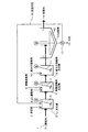
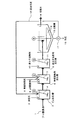
図1に示す処理方法においては、例えばフッ素含有水としてのフッ酸排水1が、第一工程としてのカルシウム反応槽(Ca反応槽)2に送られ、カルシウム化合物として消石灰3や塩化カルシウム(本実施態様では、消石灰3)が添加されて攪拌機4により攪拌され、フッ化カルシウムが生成される。このとき、後述の返送汚泥も添加される。Ca反応槽2における反応pHは、3〜12、好ましくは4〜11に維持される。
In the treatment method shown in FIG. 1, for example, hydrofluoric
Ca反応槽2からの排水は、第二工程としての無機凝集剤反応槽5に導入され、アルミニウム系凝集剤(アルミニウム塩)からなる無機凝集剤6が添加され、攪拌機7により攪拌されて不溶化物が生成される。アルミニウム系凝集剤としては、一般にPAC(ポリ塩化アルミニウム)や硫酸バンド等が用いられ、反応pHは5〜8.5、好ましくは、6〜7.5に維持される。pH調整のためにはpH調整剤8が添加されることが好ましい。
The waste water from the
上記pH調整に酸、アルカリを用いる場合、種類は特に限定されるものではないが、硫酸、塩酸、硝酸、水酸化ナトリウム等が用いられる。 When acid or alkali is used for the pH adjustment, the type is not particularly limited, but sulfuric acid, hydrochloric acid, nitric acid, sodium hydroxide and the like are used.
本実施態様では、さらに、第三工程として、無機凝集剤反応槽5からの排水が高分子凝集剤反応槽9に導入され、高分子凝集剤10が添加されて攪拌機11により攪拌される。この高分子凝集剤10は、不溶化物の凝集性を高め、その後段の固液分離性を向上させるために添加される。
In this embodiment, as a third step, the waste water from the inorganic flocculant reaction tank 5 is introduced into the polymer flocculant reaction tank 9, and the polymer flocculant 10 is added and stirred by the
高分子凝集剤反応槽9からの排水は、本実施態様では固液分離工程を実施する、緩攪拌機12を備えた沈殿槽13に導入され、沈殿処理による上澄液としての処理水14が所定の行き先に送られるとともに、沈殿分離された汚泥15の一部は排出され、他の一部は返送汚泥16としてポンプ17によりCa反応槽2に返送される。この固液分離ついては、膜分離や加圧浮上分離、沈降分離等が挙げられるが、特に限定するものではない。
The waste water from the polymer flocculant reaction tank 9 is introduced into a precipitation tank 13 equipped with a
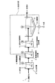
図2に示す処理方法においては、図1に示した処理方法に比べ、返送汚泥16の返送先が無機凝集剤反応槽5とされており、その他の構成は実質的に図1に示した処理方法と同じである。 In the processing method shown in FIG. 2, compared with the processing method shown in FIG. 1, the return destination of the return sludge 16 is the inorganic flocculant reaction tank 5, and the other configuration is substantially the processing shown in FIG. The method is the same.
このように、固液分離された汚泥の一部が、第一工程または第二工程に返送されるが(図1、図2)、汚泥再生処理を行う場合には、酸またはアルカリを添加して処理を行う。例えば図3、図4に示すように、汚泥返送ラインに攪拌機18を備えた汚泥再生槽19を設け、酸またはアルカリを添加して再生処理を行う。図示例では、この汚泥再生槽19にも消石灰3が添加されている。酸処理の場合はpH4以下、好ましくは3〜4の範囲とし、アルカリ処理の場合はpH9以上、好ましくは10〜12の範囲とする。酸、アルカリの添加方法は特に限定するものではなく、図示例のようにライン途中に汚泥再生用の反応槽を設けてもよいし、汚泥返送ラインに直接注入しても構わない。
In this way, a part of the sludge separated into solid and liquid is returned to the first step or the second step (FIGS. 1 and 2), but when performing sludge regeneration treatment, acid or alkali is added. Process. For example, as shown in FIG. 3 and FIG. 4, a sludge regeneration tank 19 equipped with a
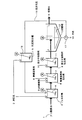
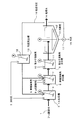
本発明に係るフッ素、リン含有水の処理方法においては、上記返送汚泥16が、第一工程および第二工程の両方に返送される。図5に示す本発明の第1実施態様に係る処理方法では、固液分離された返送汚泥16が、そのまま、第一工程のCa反応槽2、第二工程の無機凝集剤反応槽5にそれぞれ返送される。
In the method for treating fluorine and phosphorus-containing water according to the present invention, the return sludge 16 is returned to both the first step and the second step. In the treatment method according to the first embodiment of the present invention shown in FIG. 5, the returned sludge 16 that has been subjected to solid-liquid separation is directly applied to the
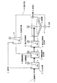
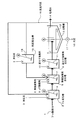
図6に示す本発明の第2実施態様に係る処理方法では、固液分離された返送汚泥16が、汚泥再生槽19で再生処理され、再生処理後の汚泥が第一工程のCa反応槽2と第二工程の無機凝集剤反応槽5にそれぞれに返送される。
In the treatment method according to the second embodiment of the present invention shown in FIG. 6, the returned sludge 16 subjected to solid-liquid separation is regenerated in the sludge regeneration tank 19, and the sludge after the regeneration process is the first stage
図7に示す本発明の第3実施態様に係る処理方法では、固液分離された返送汚泥16のうち未再生の汚泥が第一工程のCa反応槽2に返送され、第二工程の無機凝集剤反応槽5には、汚泥再生槽19で再生処理された汚泥が返送される。
In the treatment method according to the third embodiment of the present invention shown in FIG. 7, unregenerated sludge is returned to the
図5〜図7に示したいずれの方法においても、処理性能を低下させることなく、汚泥の凝集性、脱水性向上が可能であり、特に図6、図7に示した処理方法においては、無機凝集剤の添加量を低減することも可能である。 In any of the methods shown in FIG. 5 to FIG. 7, it is possible to improve the cohesiveness and dewaterability of sludge without deteriorating the treatment performance. In particular, in the treatment methods shown in FIG. 6 and FIG. It is also possible to reduce the amount of flocculant added.
図1〜図4に示した処理フロー(比較例)と図5〜図7に示した処理フロー(実施例)とについて、以下の条件で試験した。
通水条件:原水流入量100L/h、各反応槽25L、汚泥再生槽5L
被処理水:フッ化ナトリウム調整溶液(F=30mg/L)
Ca反応槽(pH10):消石灰を処理水残留Caが400mg/Lになる理論量添加
無機凝集剤反応槽(pH7):PACを300〜2000mg/L添加
高分子凝集剤反応槽:”オルフロック”OA−23を2mg/L添加
汚泥再生槽(pH11):消石灰をpH11になるまで添加
The processing flow (comparative example) shown in FIGS. 1 to 4 and the processing flow (example) shown in FIGS. 5 to 7 were tested under the following conditions.
Water flow conditions: Raw water inflow rate 100L / h, each reaction tank 25L, sludge regeneration tank 5L
Water to be treated: sodium fluoride adjustment solution (F = 30 mg / L)
Ca reaction tank (pH 10): Theoretical amount added inorganic flocculant reaction tank (pH 7) in which the treated water residual Ca is 400 mg / L: PAC 300-2000 mg / L added polymer flocculant reaction tank: “Olflock” OA-23 2mg / L addition sludge regeneration tank (pH 11): Add slaked lime until
結果を表1に示す。表1において、比較例1−1〜1−11は、図1〜図4に示した従来法によるもの、実施例2−1〜2−11は図5〜図7に示した本発明方法によるものである。これら実施例のうち、実施例2−1〜2−6は、とくに、第一工程と第二工程への汚泥返送量の比率を1:2〜30の範囲としたもので、より好ましい例である。 The results are shown in Table 1. In Table 1, Comparative Examples 1-1 to 1-11 are based on the conventional method shown in FIGS. 1 to 4, and Examples 2-1 to 2-11 are based on the method of the present invention shown in FIGS. Is. Among these examples, Examples 2-1 to 2-6 are particularly preferable examples in which the ratio of the amount of sludge returned to the first process and the second process is in the range of 1: 2 to 30. is there.

表1に示したように、各比較例、各実施例における結果は以下のようになった。
比較例1−1(基本データ)においては、汚泥返送なしであり、PAC300mg/Lでは処理水のF(フッ素)は18mg/Lにしかならなかった。比較例1−2も汚泥返送なしであり、処理水についてF=8mg/Lにするには、PACが2000mg/L必要であった。比較例1−3では、Ca反応槽に汚泥を返送したので、Ca反応槽のF値が下がっており、その結果処理水質は向上した。汚泥含水率も低下したが、PAC添加量に対してはさらなる低下が望まれる値であった。比較例1−4でCa反応槽への汚泥返送率を増加したら、却ってCa反応槽のF値が悪化し、返送汚泥による妨害が若干見られた。ただし、汚泥含水率は低下した。比較例1−5でCa反応槽への汚泥返送率をさらに増加したら、Ca反応槽のF値がさらに悪化したが、汚泥含水率は低下した。比較例1−6では、汚泥返送先を無機凝集剤反応槽としたが、比較例1−1に比べ、水質改善効果は全くなかった。ただし、汚泥含水率は比較例1−1より低下した。比較例1−7では、汚泥再生後Ca反応槽に返送したところ、水質が向上し、汚泥含水率も低く抑えられた。比較例1−8で再生汚泥の返送率を増加したところ、却ってCa反応槽のF値が悪化した。比較例1−9、1−10で再生汚泥の返送先を無機凝集剤反応槽としたところ、Ca反応槽においては比較例1−1と同等性能であり、汚泥再生の効果により、処理水質は向上した。比較例1−11で再生汚泥の返送率を40%に増加したところ、汚泥濃度が上がりすぎて凝集不良となった。
As shown in Table 1, the results in each comparative example and each example were as follows.
In Comparative Example 1-1 (basic data), sludge was not returned, and F (fluorine) of treated water was only 18 mg / L with PAC 300 mg / L. In Comparative Example 1-2, sludge was not returned, and PAC was required to be 2000 mg / L for F = 8 mg / L for the treated water. In Comparative Example 1-3, since sludge was returned to the Ca reaction tank, the F value of the Ca reaction tank was lowered, and as a result, the treated water quality was improved. Although the sludge moisture content also decreased, it was a value for which further reduction was desired with respect to the PAC addition amount. When the sludge return rate to the Ca reaction tank was increased in Comparative Example 1-4, the F value of the Ca reaction tank was deteriorated, and some disturbance due to the returned sludge was seen. However, the sludge moisture content decreased. When the sludge return rate to the Ca reaction tank was further increased in Comparative Example 1-5, the F value of the Ca reaction tank was further deteriorated, but the sludge moisture content was lowered. In Comparative Example 1-6, the sludge return destination was an inorganic flocculant reaction tank, but there was no water quality improvement effect as compared with Comparative Example 1-1. However, the sludge moisture content was lower than that of Comparative Example 1-1. In Comparative Example 1-7, when the sludge was returned to the Ca reactor after regeneration, the water quality was improved and the sludge moisture content was also kept low. When the return rate of the regenerated sludge was increased in Comparative Example 1-8, the F value of the Ca reaction tank deteriorated on the contrary. In Comparative Examples 1-9 and 1-10, when the return destination of the regenerated sludge was an inorganic flocculant reaction tank, the Ca reaction tank had the same performance as Comparative Example 1-1. Improved. In Comparative Example 1-11, the recycled sludge return rate was increased to 40%.
実施例2−1、2−4においては、処理水質は比較例1−3、1−4と同等であったが、汚泥の総返送率を上げられるので、汚泥含水率が低下した。実施例2−2、2−5においては、汚泥再生効果を良好に発揮させることができ、少ないPAC添加量でも処理水質を向上できた。実施例2−3、2−6の結果から、Ca反応槽に返送する汚泥は、再生したものより再生していないものの方が若干良い。再生した汚泥中のアルミニウムは溶解しており、よりフッ化カルシウム形成に対する悪影響が大きいためと考えられる。 In Examples 2-1 and 2-4, the quality of the treated water was the same as that of Comparative Examples 1-3 and 1-4, but the sludge water content decreased because the total return rate of sludge could be increased. In Examples 2-2 and 2-5, the sludge regeneration effect could be exhibited satisfactorily, and the quality of the treated water could be improved even with a small PAC addition amount. From the results of Examples 2-3 and 2-6, the sludge to be returned to the Ca reaction tank is slightly better when it is not regenerated than when it is regenerated. This is probably because the aluminum in the regenerated sludge is dissolved and has a greater adverse effect on calcium fluoride formation.
実施例2−7においては、良好な処理水質、汚泥含水率は得られたものの、Ca反応槽への汚泥返送比率が低いため(無機凝集剤反応槽への汚泥返送比率が高いため)、さらなる性能改善が望まれる。実施例2−7において汚泥返送量を増やしたが、Ca反応槽への汚泥返送比率が低いため(無機凝集剤反応槽への汚泥返送比率が高いため)、やはりさらなる性能改善が望まれる。実施例2−9〜2−11においては、逆に無機凝集剤反応槽への汚泥返送比率が低いため、汚泥含水率も高く、さらなる性能改善が望まれる。これら実施例2−1〜2−6と、実施例2−7〜2−11の結果から、本発明においては、第一工程と第二工程への汚泥返送量の比率を1:2〜30の範囲とすることが好ましいことが分かる。 In Example 2-7, although good treated water quality and sludge moisture content were obtained, since the sludge return ratio to the Ca reaction tank is low (since the sludge return ratio to the inorganic flocculant reaction tank is high), further A performance improvement is desired. Although the sludge return amount was increased in Example 2-7, since the sludge return ratio to the Ca reaction tank is low (since the sludge return ratio to the inorganic flocculant reaction tank is high), further performance improvement is also desired. In Examples 2-9 to 2-11, since the sludge return ratio to the inorganic flocculant reaction tank is low, the sludge moisture content is also high, and further performance improvement is desired. From the results of Examples 2-1 to 2-6 and Examples 2-7 to 2-11, in the present invention, the ratio of the sludge return amount to the first step and the second step is set to 1: 2 to 30. It can be seen that it is preferable to set the range.
なお、上記各比較例、各実施例は、フッ素含有水に関して比較したが、本発明に係る処理方法は、同様に、リン含有水に対しても適用でき、同様の作用、効果が得られる。 In addition, although each said comparative example and each Example compared regarding fluorine-containing water, the processing method which concerns on this invention is similarly applicable also to phosphorus containing water, and the same effect | action and effect are acquired.
本発明に係るフッ素、リン含有水の処理方法は、フッ素やリンを含有するあらゆる廃水の処理に適用でき、とくにエレクトロニクス産業廃水の処理に好適である。 The method for treating fluorine and phosphorus-containing water according to the present invention can be applied to the treatment of all wastewater containing fluorine and phosphorus, and is particularly suitable for the treatment of waste water from the electronics industry.
1 フッ素含有水としてのフッ酸排水
2 第一工程としてのカルシウム反応槽(Ca反応槽)
3 カルシウム化合物としての消石灰
4、7、11、18 攪拌機
5 第二工程としての無機凝集剤反応槽
6 アルミニウム系凝集剤(アルミニウム塩)からなる無機凝集剤
8 pH調整剤
9 第三工程としての高分子凝集剤反応槽
10 高分子凝集剤
12 緩攪拌機
13 固液分離工程としての沈殿槽
14 処理水
15 沈殿分離された汚泥
16 返送汚泥
17 ポンプ
19 汚泥再生槽
1 Hydrofluoric acid wastewater as fluorine-containing
3 Slaked lime as a
Claims (4)
該第一工程からの排水にアルミニウム塩を添加することにより不溶化物を生成する第二工程と、
生成した不溶化物を含む汚泥を分離して処理水を得る固液分離工程を有し、
前記固液分離工程により分離された汚泥の一部を第一工程および第二工程の両方へ返送することを特徴とする、フッ素、リン含有水の処理方法。 A first step in which a calcium compound is allowed to act on fluorine or / and phosphorus-containing water to insolubilize most of the fluorine or / and phosphorus as calcium fluoride or / and calcium phosphate;
A second step of producing an insolubilized product by adding an aluminum salt to the waste water from the first step;
It has a solid-liquid separation process to separate the sludge containing the insolubilized product and obtain treated water
A method for treating fluorine and phosphorus-containing water, wherein a part of the sludge separated by the solid-liquid separation step is returned to both the first step and the second step.
Priority Applications (1)
| Application Number | Priority Date | Filing Date | Title |
|---|---|---|---|
| JP2004117905A JP4689186B2 (en) | 2004-04-13 | 2004-04-13 | Fluorine-containing water treatment method |
Applications Claiming Priority (1)
| Application Number | Priority Date | Filing Date | Title |
|---|---|---|---|
| JP2004117905A JP4689186B2 (en) | 2004-04-13 | 2004-04-13 | Fluorine-containing water treatment method |
Publications (2)
| Publication Number | Publication Date |
|---|---|
| JP2005296837A true JP2005296837A (en) | 2005-10-27 |
| JP4689186B2 JP4689186B2 (en) | 2011-05-25 |
Family
ID=35329030
Family Applications (1)
| Application Number | Title | Priority Date | Filing Date |
|---|---|---|---|
| JP2004117905A Expired - Fee Related JP4689186B2 (en) | 2004-04-13 | 2004-04-13 | Fluorine-containing water treatment method |
Country Status (1)
| Country | Link |
|---|---|
| JP (1) | JP4689186B2 (en) |
Cited By (7)
| Publication number | Priority date | Publication date | Assignee | Title |
|---|---|---|---|---|
| JP2006167631A (en) * | 2004-12-16 | 2006-06-29 | Kurita Water Ind Ltd | Method and apparatus for treating fluorine-containing wastewater containing phosphoric acid |
| JP2007275757A (en) * | 2006-04-06 | 2007-10-25 | Nippon Rensui Co Ltd | Method for coagulating sedimentation of ion-containing wastewater |
| WO2008120704A1 (en) * | 2007-03-30 | 2008-10-09 | Kurita Water Industries Ltd. | Fluorine-containing wastewater treating apparatus and treating method |
| JP2013119061A (en) * | 2011-12-07 | 2013-06-17 | Japan Organo Co Ltd | Flocculating sedimentation apparatus |
| JP2014200744A (en) * | 2013-04-05 | 2014-10-27 | オルガノ株式会社 | Method of treating waste liquid containing boron fluoride ion and apparatus of treating waste liquid containing boron fluoride ion |
| US8911631B2 (en) | 2011-05-10 | 2014-12-16 | Kabushiki Kaisha Toshiba | Fluorine recovering apparatus and method for recovering fluorine |
| US8986541B2 (en) | 2011-06-08 | 2015-03-24 | Kabushiki Kaisha Toshiba | Copper recovery apparatus |
Families Citing this family (1)
| Publication number | Priority date | Publication date | Assignee | Title |
|---|---|---|---|---|
| CN103112966A (en) * | 2013-02-25 | 2013-05-22 | 张卫东 | Recovery treating method for treating wastewater before coating sheet metal part |
Citations (10)
| Publication number | Priority date | Publication date | Assignee | Title |
|---|---|---|---|---|
| JPS51142864A (en) * | 1975-06-04 | 1976-12-08 | Nippon Chem Ind Co Ltd:The | Treating method of fluorine ion-containing waste liquor |
| JPH0736911B2 (en) * | 1993-03-11 | 1995-04-26 | 日本電気株式会社 | Fluorine-containing wastewater treatment method |
| JPH08197070A (en) * | 1995-01-24 | 1996-08-06 | Kurita Water Ind Ltd | Fluorine-containing water treatment method |
| JPH091154A (en) * | 1995-06-16 | 1997-01-07 | Kurita Water Ind Ltd | Treatment method for wastewater containing phosphoric acid |
| JPH105769A (en) * | 1996-06-27 | 1998-01-13 | Nec Environment Eng Ltd | Treatment of fluorine-containing discharge water |
| JPH1034166A (en) * | 1996-07-22 | 1998-02-10 | Japan Organo Co Ltd | Apparatus for treating fluorine-containing waste water and method therefor |
| JPH10137744A (en) * | 1996-11-11 | 1998-05-26 | Nec Corp | Treatment of waste water containing fluorine |
| JPH10230282A (en) * | 1997-02-17 | 1998-09-02 | Japan Organo Co Ltd | Treatment of fluorine-containing waste water |
| JP2000084570A (en) * | 1998-07-17 | 2000-03-28 | Nec Corp | Treatment of fluorine-containing waste water and treating apparatus |
| JP2001009468A (en) * | 1999-06-25 | 2001-01-16 | Kurita Water Ind Ltd | Fluorine removal method and apparatus |
-
2004
- 2004-04-13 JP JP2004117905A patent/JP4689186B2/en not_active Expired - Fee Related
Patent Citations (10)
| Publication number | Priority date | Publication date | Assignee | Title |
|---|---|---|---|---|
| JPS51142864A (en) * | 1975-06-04 | 1976-12-08 | Nippon Chem Ind Co Ltd:The | Treating method of fluorine ion-containing waste liquor |
| JPH0736911B2 (en) * | 1993-03-11 | 1995-04-26 | 日本電気株式会社 | Fluorine-containing wastewater treatment method |
| JPH08197070A (en) * | 1995-01-24 | 1996-08-06 | Kurita Water Ind Ltd | Fluorine-containing water treatment method |
| JPH091154A (en) * | 1995-06-16 | 1997-01-07 | Kurita Water Ind Ltd | Treatment method for wastewater containing phosphoric acid |
| JPH105769A (en) * | 1996-06-27 | 1998-01-13 | Nec Environment Eng Ltd | Treatment of fluorine-containing discharge water |
| JPH1034166A (en) * | 1996-07-22 | 1998-02-10 | Japan Organo Co Ltd | Apparatus for treating fluorine-containing waste water and method therefor |
| JPH10137744A (en) * | 1996-11-11 | 1998-05-26 | Nec Corp | Treatment of waste water containing fluorine |
| JPH10230282A (en) * | 1997-02-17 | 1998-09-02 | Japan Organo Co Ltd | Treatment of fluorine-containing waste water |
| JP2000084570A (en) * | 1998-07-17 | 2000-03-28 | Nec Corp | Treatment of fluorine-containing waste water and treating apparatus |
| JP2001009468A (en) * | 1999-06-25 | 2001-01-16 | Kurita Water Ind Ltd | Fluorine removal method and apparatus |
Cited By (9)
| Publication number | Priority date | Publication date | Assignee | Title |
|---|---|---|---|---|
| JP2006167631A (en) * | 2004-12-16 | 2006-06-29 | Kurita Water Ind Ltd | Method and apparatus for treating fluorine-containing wastewater containing phosphoric acid |
| JP2007275757A (en) * | 2006-04-06 | 2007-10-25 | Nippon Rensui Co Ltd | Method for coagulating sedimentation of ion-containing wastewater |
| WO2008120704A1 (en) * | 2007-03-30 | 2008-10-09 | Kurita Water Industries Ltd. | Fluorine-containing wastewater treating apparatus and treating method |
| JPWO2008120704A1 (en) * | 2007-03-30 | 2010-07-15 | 栗田工業株式会社 | Fluorine-containing wastewater treatment apparatus and treatment method |
| US8911631B2 (en) | 2011-05-10 | 2014-12-16 | Kabushiki Kaisha Toshiba | Fluorine recovering apparatus and method for recovering fluorine |
| US8986541B2 (en) | 2011-06-08 | 2015-03-24 | Kabushiki Kaisha Toshiba | Copper recovery apparatus |
| US9701553B2 (en) | 2011-06-08 | 2017-07-11 | Kabushiki Kaisha Toshiba | Copper recovery apparatus |
| JP2013119061A (en) * | 2011-12-07 | 2013-06-17 | Japan Organo Co Ltd | Flocculating sedimentation apparatus |
| JP2014200744A (en) * | 2013-04-05 | 2014-10-27 | オルガノ株式会社 | Method of treating waste liquid containing boron fluoride ion and apparatus of treating waste liquid containing boron fluoride ion |
Also Published As
| Publication number | Publication date |
|---|---|
| JP4689186B2 (en) | 2011-05-25 |
Similar Documents
| Publication | Publication Date | Title |
|---|---|---|
| JP4689187B2 (en) | Method and apparatus for treating fluorine-containing water | |
| JP4689186B2 (en) | Fluorine-containing water treatment method | |
| JP2006167631A (en) | Method and apparatus for treating fluorine-containing wastewater containing phosphoric acid | |
| JP4351867B2 (en) | Fluorine or phosphorus-containing water treatment equipment | |
| JPH1133560A (en) | Coagulation treatment method for CMP effluent | |
| JP2001340870A (en) | Treatment method for fluorine-containing wastewater | |
| JP3903591B2 (en) | Treatment method for fluorine and phosphorus containing wastewater | |
| JP6393373B2 (en) | Method for recovering phosphoric acid from waste | |
| JP4572812B2 (en) | Fluorine-containing water treatment method | |
| JP4863694B2 (en) | Method and apparatus for fluorinating chelating agent-containing water | |
| JP6723058B2 (en) | Water treatment method and water treatment system | |
| JPH10230282A (en) | Treatment of fluorine-containing waste water | |
| JP6045966B2 (en) | Fluorine-containing wastewater treatment method and fluorine-containing wastewater treatment equipment | |
| JP4140050B2 (en) | Fluorine-containing water treatment method and fluorine-containing water treatment apparatus | |
| JP3349637B2 (en) | Fluorine-containing wastewater treatment apparatus and method | |
| JP6162375B2 (en) | Method for recovering phosphoric acid from waste | |
| JP4581160B2 (en) | Method for treating phosphorus-containing water | |
| JP4525601B2 (en) | Treatment method for fluorine-containing wastewater | |
| JP4350078B2 (en) | Treatment method for fluorine-containing wastewater | |
| JP4640149B2 (en) | Fluorine-containing water treatment method | |
| JP4894139B2 (en) | Method and apparatus for treating phosphoric acid-containing liquid | |
| JP2008006382A (en) | Method of treating oil-containing waste water | |
| JP2002263676A (en) | Wastewater treatment method and apparatus | |
| JP6723057B2 (en) | Water treatment method and water treatment system | |
| JP2006167633A (en) | Treating method of fluorine-containing water |
Legal Events
| Date | Code | Title | Description |
|---|---|---|---|
| A621 | Written request for application examination |
Free format text: JAPANESE INTERMEDIATE CODE: A621 Effective date: 20070301 |
|
| A977 | Report on retrieval |
Free format text: JAPANESE INTERMEDIATE CODE: A971007 Effective date: 20100126 |
|
| A131 | Notification of reasons for refusal |
Free format text: JAPANESE INTERMEDIATE CODE: A131 Effective date: 20100212 |
|
| A521 | Request for written amendment filed |
Free format text: JAPANESE INTERMEDIATE CODE: A523 Effective date: 20100406 |
|
| A131 | Notification of reasons for refusal |
Free format text: JAPANESE INTERMEDIATE CODE: A131 Effective date: 20100917 |
|
| A521 | Request for written amendment filed |
Free format text: JAPANESE INTERMEDIATE CODE: A523 Effective date: 20101027 |
|
| TRDD | Decision of grant or rejection written | ||
| A01 | Written decision to grant a patent or to grant a registration (utility model) |
Free format text: JAPANESE INTERMEDIATE CODE: A01 Effective date: 20110215 |
|
| A01 | Written decision to grant a patent or to grant a registration (utility model) |
Free format text: JAPANESE INTERMEDIATE CODE: A01 |
|
| A61 | First payment of annual fees (during grant procedure) |
Free format text: JAPANESE INTERMEDIATE CODE: A61 Effective date: 20110216 |
|
| R150 | Certificate of patent or registration of utility model |
Ref document number: 4689186 Country of ref document: JP Free format text: JAPANESE INTERMEDIATE CODE: R150 Free format text: JAPANESE INTERMEDIATE CODE: R150 |
|
| FPAY | Renewal fee payment (event date is renewal date of database) |
Free format text: PAYMENT UNTIL: 20140225 Year of fee payment: 3 |
|
| R250 | Receipt of annual fees |
Free format text: JAPANESE INTERMEDIATE CODE: R250 |
|
| R250 | Receipt of annual fees |
Free format text: JAPANESE INTERMEDIATE CODE: R250 |
|
| R250 | Receipt of annual fees |
Free format text: JAPANESE INTERMEDIATE CODE: R250 |
|
| R250 | Receipt of annual fees |
Free format text: JAPANESE INTERMEDIATE CODE: R250 |
|
| R250 | Receipt of annual fees |
Free format text: JAPANESE INTERMEDIATE CODE: R250 |
|
| R250 | Receipt of annual fees |
Free format text: JAPANESE INTERMEDIATE CODE: R250 |
|
| R250 | Receipt of annual fees |
Free format text: JAPANESE INTERMEDIATE CODE: R250 |
|
| R250 | Receipt of annual fees |
Free format text: JAPANESE INTERMEDIATE CODE: R250 |
|
| LAPS | Cancellation because of no payment of annual fees |