JP2005296882A - Painting tool - Google Patents
Painting tool Download PDFInfo
- Publication number
- JP2005296882A JP2005296882A JP2004119804A JP2004119804A JP2005296882A JP 2005296882 A JP2005296882 A JP 2005296882A JP 2004119804 A JP2004119804 A JP 2004119804A JP 2004119804 A JP2004119804 A JP 2004119804A JP 2005296882 A JP2005296882 A JP 2005296882A
- Authority
- JP
- Japan
- Prior art keywords
- molded product
- movable plate
- coating
- base
- peripheral side
- Prior art date
- Legal status (The legal status is an assumption and is not a legal conclusion. Google has not performed a legal analysis and makes no representation as to the accuracy of the status listed.)
- Withdrawn
Links
- 238000010422 painting Methods 0.000 title abstract description 21
- 230000002093 peripheral effect Effects 0.000 claims abstract description 28
- 239000003973 paint Substances 0.000 claims abstract description 12
- 239000011248 coating agent Substances 0.000 claims description 53
- 238000000576 coating method Methods 0.000 claims description 53
- 239000013013 elastic material Substances 0.000 claims description 6
- 239000000463 material Substances 0.000 claims description 6
- 230000000881 depressing effect Effects 0.000 claims 1
- 238000000465 moulding Methods 0.000 abstract description 8
- 239000006185 dispersion Substances 0.000 abstract description 2
- 230000009545 invasion Effects 0.000 abstract 1
- XUIMIQQOPSSXEZ-UHFFFAOYSA-N Silicon Chemical compound [Si] XUIMIQQOPSSXEZ-UHFFFAOYSA-N 0.000 description 5
- 229910052710 silicon Inorganic materials 0.000 description 5
- 239000010703 silicon Substances 0.000 description 5
- 238000005507 spraying Methods 0.000 description 2
- 230000000873 masking effect Effects 0.000 description 1
- 238000000034 method Methods 0.000 description 1
- 238000012986 modification Methods 0.000 description 1
- 230000004048 modification Effects 0.000 description 1
- 229920001296 polysiloxane Polymers 0.000 description 1
Images
Landscapes
- Details Or Accessories Of Spraying Plant Or Apparatus (AREA)
Abstract
Description
本発明は成形品の塗装に際して、塗装部と非塗装部を塗り分けるために用いられる塗装用治具に関するものであり、特に、成形品の形状のばらつきを吸収して確実に塗装部と非塗装部を塗り分けることができる塗装用治具に関するものである。 The present invention relates to a coating jig used to paint a painted part and a non-painted part when painting a molded product, and in particular, absorbs variations in the shape of the molded product to ensure that the painted part and the non-coated part are applied. The present invention relates to a coating jig capable of coating the parts separately.
従来から、例えば、DVDプレーヤのフロントパネル等の成形品について所定の塗装部のみを塗装するために塗装用治具が用いられている。このような塗装用治具は成形品の非塗装部を覆うように成形品に取り付けられて用いられ、成形品は塗装用治具に覆われていない部分に塗料を吹付けることにより塗り分けされる。 2. Description of the Related Art Conventionally, for example, a coating jig is used to coat only a predetermined coating portion of a molded product such as a front panel of a DVD player. Such a coating jig is used by being attached to the molded product so as to cover the non-painted part of the molded product, and the molded product is applied separately by spraying paint on the part not covered by the coating jig. The
しかしながら、単に、塗装用治具を成形品に載せて塗装面を覆うだけの従来の塗装用治具では、成形品と塗装用治具との間に隙間が生じ易く、塗装時に塗料がこの隙間から入り込んでしまい、塗装を施す塗装部と塗装を施さない非塗装部の塗り分けの境界線が不明瞭になることがあった。 However, with a conventional painting jig that simply covers the painted surface by placing the painting jig on the molded product, a gap is likely to be formed between the molded product and the painting jig, and the paint is not covered during painting. In some cases, the boundary line between the painted portion where the paint is applied and the non-painted portion where the paint is not applied is unclear.
一方、塗装用マスクの縁部に設けた突出部を成形品の色分け境界部に設けた凹溝に挿入して係着し、この状態で塗装することにより凹溝を境界として塗装面を塗り分ける塗装用マスクが知られている(例えば、特許文献1参照)。また、上述の構成に加え、先端が鈎状の棒状部材を有する上側マスク部材とこの棒状部材が嵌入される孔を有する下側マスク部材とを備え、成形品をこれらマスク部材で弾性的に挟持することにより、塗装面を塗り分ける塗装用マスキング装置が知られている(例えば、特許文献2参照)。
しかしながら、上述した特許文献1及び特許文献2に記載の発明においては、凹溝を境界として鮮明に塗装面を塗り分けることができるものの、成形条件等により個々の成形品の寸法がばらついた場合には、成形品と塗装用治具の間に隙間が生じる虞があり、そのような場合には鮮明な塗り分けが困難となる。特に、成形品のサイズが大きくなればなるほど収縮や反り等に起因する寸法のばらつきが大きくなり、塗り分けは困難となる。
However, in the inventions described in
本発明は、上述した問題点を解決するためになされたものであり、成形条件による成形品の寸法のばらつきを吸収して成形品に密着し、非塗装部へ塗料が回り込まないようにして塗装部と非塗装部の塗り分けが確実にできる塗装用治具を提供することを目的とする。 The present invention has been made in order to solve the above-described problems, and is applied in such a manner that the dispersion of the dimension of the molded product due to molding conditions is absorbed and adhered to the molded product so that the paint does not enter the non-painted portion. An object of the present invention is to provide a coating jig that can reliably coat a non-painted portion and a non-painted portion.
上記目的を達成するために請求項1の発明は、開口窓部を有する矩形板状の正面部と、この正面部の周縁に背面側に延設された周側面部とを有する成形品の背面側の非塗装部を除いて塗装するために用いられ、前記成形品が正面側を上面として載置される基台を有した塗装用治具であって、前記基台には、前記成形品の長手方向の周側面部、及び前記開口窓部の縁の位置に対応して凹状の溝部が設けられ、この溝部内に挿入されたバネにより上方に付勢された可動板が前記溝部に案内され、かつ、上端部が基台の上面より突出した状態で設けられており、前記可動板の上面には、該可動板が前記成形品と密着し得るように弾性を有する材料が取り付けられ、前記可動板は、その上面に前記成形品の長手方向の周側面部の背面が当接される外可動板と、前記開口窓部の縁が当接される内可動板とを含み、前記外可動板は、前記成形品の周側面部の形状のばらつきを吸収して該周側面部に当接し得るように長さ方向に複数に分割されており、前記成形品を前記基台上に載置する際に、成形品の長手方向の周側面部を前記外可動板に、成形品の開口窓部の縁を前記内可動板にそれぞれ当接させ、前記バネの付勢力に抗して成形品の短手方向の周側面部が基台上面に当接するまで成形品を押下することにより、成形品の周側面部を基台及び外可動板に密着させ、かつ、成形品の開口窓部の縁を内可動板に密着させて、塗料の非塗装部への回り込みが生じないようにしたものである。
In order to achieve the above object, the invention according to
この構成においては、塗装用治具は成形品との接触面に合わせて可動する可動板を備えているため、成形品ごとに寸法がばらついていても、可動板が成形品の形状のばらつきを吸収して成形品に密着して当接する。特に、矩形板状の正面部を有する成形品は、短手方向に比べて長手方向の形状のばらつきが通常大きくなるが、外可動板が長さ方向に複数に分割されているため、分割されたそれぞれの外可動板が成形品の長手方向の形状のばらつきを吸収して成形品に密着して当接する。 In this configuration, the coating jig includes a movable plate that can move according to the contact surface with the molded product. Therefore, even if the dimensions vary from molded product to molded product, the movable plate may cause variations in the shape of the molded product. Absorb and adhere closely to the molded product. In particular, a molded product having a rectangular plate-like front part usually has a larger variation in shape in the longitudinal direction than in the short direction, but is divided because the outer movable plate is divided into a plurality in the length direction. Further, each outer movable plate absorbs the variation in the shape of the molded product in the longitudinal direction and comes into close contact with the molded product.
また、塗装用治具は繰り返して使用されるため、基台や可動板には繰り返しの使用に耐え得る材料が通常選択されるが、このような可動板の上面に弾性を有する材料を取り付けることにより、成形品を可動板上に載置する際、弾性を有する材料が変形し、成形品と塗装用治具の密着性を高めることができる。なお、弾性を有する材料としては、シリコンやゴム等が挙げられる。 Also, since the coating jig is used repeatedly, a material that can withstand repeated use is usually selected for the base and the movable plate, but an elastic material is attached to the upper surface of such a movable plate. Thus, when the molded product is placed on the movable plate, the elastic material is deformed, and the adhesion between the molded product and the coating jig can be enhanced. Note that examples of the material having elasticity include silicon and rubber.
そして、成形品を基台上に載置する際に、成形品を押下して成形品の周側面部を基台及び外可動板に密着させ、かつ、成形品の開口窓部の縁を内可動板に密着させることにより非塗装部を密閉することができ、非塗装部への塗料の回り込みを防ぐことができる。 When the molded product is placed on the base, the molded product is pressed down so that the peripheral side surface portion of the molded product is in close contact with the base and the outer movable plate, and the edge of the opening window portion of the molded product is By bringing the movable plate into close contact with the movable plate, the non-painted portion can be sealed, and the coating material can be prevented from wrapping around the non-painted portion.
請求項2の発明は、成形品の背面側の非塗装部を除いて塗装するために用いられ、前記成形品が正面側を上面として載置される基台を有した塗装用治具であって、前記基台には、前記成形品の非塗装部の位置に対応して凹状の溝部が設けられ、この溝部内に挿入された付勢手段により上方に付勢された可動板が前記溝部に案内され、かつ、上端部が基台の上面より突出した状態で設けられており、前記成形品を前記基台上に載置する際に、成形品の非塗装部を前記可動板に当接させ、前記付勢手段の付勢力に抗して成形品を押下することにより、成形品の非塗装部を可動板に密着させて、塗料の非塗装部への回り込みが生じないようにしたものである。
The invention of
この構成においては、塗装用治具は成形品との接触面に合わせて可動する可動板を備えているため、可動板が成形品の形状のばらつきを吸収して成形品に密着して当接する。 In this configuration, since the painting jig includes a movable plate that moves according to the contact surface with the molded product, the movable plate absorbs variations in the shape of the molded product and comes into close contact with the molded product. .
請求項3の発明は、請求項2に記載の発明において、前記可動板が成形品の長さ方向に複数に分割されているものである。この構成においては、可動板が成形品の長さ方向に複数に分割されているため、分割されたそれぞれの外可動板が成形品の形状のばらつきを吸収して成形品に密着して当接する。
The invention of
以上のように請求項1の発明によれば、塗装用治具は成形品との接触面に合わせて可動する可動板を備えているため、成形品ごとに寸法がばらついていた場合であっても、この可動板が成形品の形状のばらつきを吸収して成形品に当接する。ここに、外可動板は長さ方向に複数に分割されているため、分割されたそれぞれの外可動板が成形品の形状に合わせて成形品に密着して当接する。さらに、可動板の上面には、弾性を有する材料が取り付けられおり、成形品が可動板上に載置された場合にはこの材料が変形して成形品と密着するので、塗装の際に、非塗装部を密閉して塗料が回り込まないようにすることができ、塗装部と非塗装部とを確実に塗り分けることができる。 As described above, according to the first aspect of the present invention, since the coating jig includes the movable plate that moves according to the contact surface with the molded product, the dimension varies from molded product to molded product. However, this movable plate absorbs variation in the shape of the molded product and comes into contact with the molded product. Here, since the outer movable plate is divided into a plurality of portions in the length direction, each of the divided outer movable plates comes into close contact with the molded product in accordance with the shape of the molded product. Furthermore, an elastic material is attached to the upper surface of the movable plate, and when the molded product is placed on the movable plate, this material is deformed and closely contacts the molded product. The non-painted portion can be sealed to prevent the paint from flowing around, and the painted portion and the non-painted portion can be reliably applied separately.
請求項2の発明によれば、塗装用治具は成形品との接触面に合わせて可動する可動板を備えており、この可動板が成形品の形状のばらつきを吸収して成形品に密着して当接する。このため、塗装の際に非塗装部へ塗料が回り込むことがなく、塗装部と非塗装部とを確実に塗り分けることができる。
According to the invention of
請求項3の発明によれば、可動板は成形品の長さ方向に複数に分割されているため、サイズの大きい成形品においても成形品の形状のばらつきを吸収して成形品に密着して当接させることができる。このため、塗装部と非塗装部とを確実に塗り分けることができる。
According to the invention of
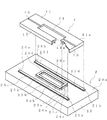
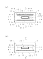
本発明の一実施形態による塗装用治具について図面を参照して説明する。図1は、塗装用治具及び塗装される成形品を示し、図2は成形品が装着される前と後の塗装用治具を示している。塗装される成形品1は、樹脂成形されたDVDプレーヤのフロントパネルを示し、この成形品1は、開口窓部14を有する矩形板状の正面部11と、この正面部11の周縁11aに背面側に延設された周側面部12,13とを備えている。周側面部12,13は、それぞれ成形品1の長手方向と短手方向のものであり、それぞれ相対向して一対ある。
A coating jig according to an embodiment of the present invention will be described with reference to the drawings. FIG. 1 shows a painting jig and a molded article to be painted, and FIG. 2 shows a painting jig before and after the molded article is mounted. The molded
塗装用治具2は、台状の基台20を主体とし、基台20には成形品1の長手方向の周側面部12、及び開口窓部14の縁14aの位置に対応して凹状の溝部21a,21b,21cがそれぞれ設けられ、後述する図3乃至図5に示されるように、溝部21a,21b,21cに挿入されたバネ22a,22b,22cにより上方に付勢された可動板23a〜23f,24a〜24dが溝部21a,21b,21cに案内された状態で設けられている。可動板23a〜23f,24a〜24dは、成形品1の長手方向の周側面部12と当接する外可動板23a〜23fと、成形品1の開口窓部14の縁14aと当接する内可動板24a〜24dにより構成されている。
The
また、可動板23a〜23f,24a〜24dの上面には、シリコン25a〜25c(弾性を有する材料)が取り付けられている。成形品1が可動板23a〜23f,24a〜24dの上に載置された際、シリコン25a〜25cが変形して成形品1と当接するため、成形品1と塗装用治具2の密着性を高めることができる。
Silicones 25a to 25c (elastic material) are attached to the upper surfaces of the movable plates 23a to 23f and 24a to 24d. When the molded
さらに、外可動板23a〜23fは長さ方向に複数に分割されている。このため、分割されたそれぞれの外可動板23a〜23fが成形品1の長手方向の周側面部12の形状に合わせて当接する。また、シリコン25a〜25cは、外可動板23a〜23c、外可動板23d〜23f、及び内可動板24a〜24dの各種類毎に1枚ずつ使用されている。このため、可動板23a〜23f,24a〜24dの継ぎ目でもシリコン25a〜25cは、隙間なく成形品1に当接することができる。
Further, the outer movable plates 23a to 23f are divided into a plurality in the length direction. For this reason, each of the divided outer movable plates 23 a to 23 f comes into contact with the shape of the peripheral side surface portion 12 in the longitudinal direction of the molded
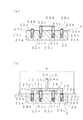
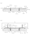
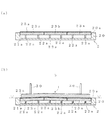
次に、成形品1を塗装する際の手順について図3乃至図5を参照して説明する。これらの図のなか、図3(a)、図4(a)、図5(a)は、成形品1が載置されていない状態での塗装用治具2を示している。外可動板23a〜23c及び内可動板24a〜24dは、バネ22a,22b,22cの付勢力により、その上端部が基台20の上面より突出した状態で配置されている。
Next, the procedure for painting the molded
また、図3(b)、図4(b)、図5(b)は、成形品1が載置された状態での塗装用治具2及び成形品1を示している。成形品1は、長手方向の周側面部12を外可動板23a〜23fに、開口窓部14の縁14aを内可動板24a〜24dにそれぞれ当接させて、成形品1の短手方向の周側面部13が基台2の上面20aに当接するまで成形品1の溝部15を押圧棒30で押下することにより基台20の上に載置される。この際、各可動板23a〜23f,24a〜24dはバネ22a,22b,22cの付勢力により上方に付勢されているため、可動板23a〜23f,24a〜24dは成形品1の形状に合わせて当接する。成形品1はこの状態で、矢印a及び矢印bの範囲に塗料を吹き付けることにより塗装される。なお、成形品1の押圧棒30との当接部は塗装されないことになるが、押圧棒30が当接する成形品1の溝部15には、塗装した後、別の部材が取り付けられるため、成形品1の外観上の問題は生じない。なお、本実施形態においては、上側から押圧棒30で押下する例を示したが、下側から吸引することにより成形品1を塗装用治具2に密着させるようにしても構わない。
3 (b), 4 (b), and 5 (b) show the
上述したように、成形品1を塗装用治具2に設置した際、成形品1の周側面部12,13が基台20及び外可動板23a〜23fに密着し、かつ、成形品1の開口窓部14の縁14aが内可動板24a〜24dに密着することにより成形品1の非塗装部は密閉される。このため、塗装の際、成形品1の非塗装部に塗料が回り込むことがなく、塗装部と非塗装部とを確実に塗り分けることができる。
As described above, when the molded
なお、本発明は上記実施形態の構成に限られることなく種々の変形が可能である。例えば、本実施形態においては、短手方向の周側面部13が、基台20に当接するものを示したが、基台20の短手方向の周側面部13に対応する位置にも外可動板を設けて、これに短手方向の周側面部13が当接するようにしても構わない。また、基台20に設けられる可動板の配置は上記実施形態に限られず、塗装される成形品の形状に合わせて非塗装部を密閉できるものであればよい。
The present invention is not limited to the configuration of the above embodiment, and various modifications can be made. For example, in the present embodiment, the peripheral side surface portion 13 in the short side direction is shown in contact with the
1 成形品
2 塗装用治具
11 正面部
12 長手方向の側面部
13 短手方向の側面部
14 開口窓部
20 基台
21a,21b,21c 溝部
22a,22b,22c バネ(付勢手段)
23a,23b,23c,23d,23e,23f 外可動板
24a,24b,24c,24d 内可動板
25a,25b,25c シリコン(弾性を有する材料)
DESCRIPTION OF
23a, 23b, 23c, 23d, 23e, 23f Outer movable plate 24a, 24b, 24c, 24d Inner movable plate 25a, 25b, 25c Silicon (material having elasticity)
Claims (3)
前記基台には、前記成形品の長手方向の周側面部、及び前記開口窓部の縁の位置に対応して凹状の溝部が設けられ、この溝部内に挿入されたバネにより上方に付勢された可動板が前記溝部に案内され、かつ、上端部が基台の上面より突出した状態で設けられており、
前記可動板の上面には、該可動板が前記成形品と密着し得るように弾性を有する材料が取り付けられ、
前記可動板は、その上面に前記成形品の長手方向の周側面部の背面が当接される外可動板と、前記開口窓部の縁が当接される内可動板とを含み、
前記外可動板は、前記成形品の周側面部の形状のばらつきを吸収して該周側面部に当接し得るように長さ方向に複数に分割されており、
前記成形品を前記基台上に載置する際に、成形品の長手方向の周側面部を前記外可動板に、成形品の開口窓部の縁を前記内可動板にそれぞれ当接させ、前記バネの付勢力に抗して成形品の短手方向の周側面部が基台上面に当接するまで成形品を押下することにより、成形品の周側面部を基台及び外可動板に密着させ、かつ、成形品の開口窓部の縁を内可動板に密着させて、塗料の非塗装部への回り込みが生じないようにしたことを特徴とする塗装用治具。 Used to paint except for the non-coating part on the back side of a molded product having a rectangular plate-like front part having an open window part and a peripheral side part extending to the back side at the periphery of the front part. And a coating jig having a base on which the molded product is placed with the front side as the upper surface,
The base is provided with a concave groove corresponding to the position of the peripheral side surface in the longitudinal direction of the molded product and the edge of the opening window, and is biased upward by a spring inserted into the groove. The movable plate is guided by the groove, and the upper end is provided in a state protruding from the upper surface of the base,
On the upper surface of the movable plate, an elastic material is attached so that the movable plate can be in close contact with the molded product,
The movable plate includes an outer movable plate whose upper surface is in contact with the back surface of the peripheral side surface portion in the longitudinal direction of the molded product, and an inner movable plate with which an edge of the opening window is in contact,
The outer movable plate is divided into a plurality of portions in the length direction so as to absorb variation in the shape of the peripheral side surface portion of the molded product and contact the peripheral side surface portion.
When placing the molded product on the base, the peripheral side surface portion in the longitudinal direction of the molded product is brought into contact with the outer movable plate, and the edge of the opening window portion of the molded product is brought into contact with the inner movable plate. The peripheral side surface of the molded product is brought into close contact with the base and the outer movable plate by depressing the molded product until the peripheral side surface in the short direction of the molded product contacts the upper surface of the base against the biasing force of the spring. The coating jig is characterized in that the edge of the opening window portion of the molded product is brought into close contact with the inner movable plate so that the coating material does not wrap around the non-coating portion.
前記基台には、前記成形品の非塗装部の位置に対応して凹状の溝部が設けられ、この溝部内に挿入された付勢手段により上方に付勢された可動板が前記溝部に案内され、かつ、上端部が基台の上面より突出した状態で設けられており、
前記成形品を前記基台上に載置する際に、成形品の非塗装部を前記可動板に当接させ、前記付勢手段の付勢力に抗して成形品を押下することにより、成形品の非塗装部を可動板に密着させて、塗料の非塗装部への回り込みが生じないようにしたことを特徴とする塗装用治具。 It is used for coating except the non-coating part on the back side of the molded product, and is a coating jig having a base on which the molded product is placed with the front side as the upper surface,
The base is provided with a concave groove corresponding to the position of the non-painted part of the molded product, and a movable plate urged upward by an urging means inserted into the groove is guided to the groove. And the upper end is provided in a state protruding from the upper surface of the base,
When placing the molded product on the base, the non-painted portion of the molded product is brought into contact with the movable plate, and the molded product is pressed down against the biasing force of the biasing means. A coating jig characterized in that a non-painted portion of a product is brought into close contact with a movable plate so that the coating does not wrap around the non-painted portion.
Priority Applications (1)
| Application Number | Priority Date | Filing Date | Title |
|---|---|---|---|
| JP2004119804A JP2005296882A (en) | 2004-04-15 | 2004-04-15 | Painting tool |
Applications Claiming Priority (1)
| Application Number | Priority Date | Filing Date | Title |
|---|---|---|---|
| JP2004119804A JP2005296882A (en) | 2004-04-15 | 2004-04-15 | Painting tool |
Publications (1)
| Publication Number | Publication Date |
|---|---|
| JP2005296882A true JP2005296882A (en) | 2005-10-27 |
Family
ID=35329073
Family Applications (1)
| Application Number | Title | Priority Date | Filing Date |
|---|---|---|---|
| JP2004119804A Withdrawn JP2005296882A (en) | 2004-04-15 | 2004-04-15 | Painting tool |
Country Status (1)
| Country | Link |
|---|---|
| JP (1) | JP2005296882A (en) |
-
2004
- 2004-04-15 JP JP2004119804A patent/JP2005296882A/en not_active Withdrawn
Similar Documents
| Publication | Publication Date | Title |
|---|---|---|
| CN101062669B (en) | Fillet | |
| CN205478713U (en) | Column structure capable of fastening and shock-proof | |
| RU2019143972A (en) | CONTROL DEVICE | |
| WO2006020592A3 (en) | Housing with functional overmold | |
| JP5623869B2 (en) | Release operation piece for parts holder | |
| JP2005219534A (en) | Vehicle roof molding mounting structure and mounting clip | |
| KR20180014719A (en) | Gasket and its manufacturing method | |
| AR035101A1 (en) | METHOD AND APPLIANCE FOR ASSEMBLING CONTACT LENS MOLDS | |
| JP6468927B2 (en) | Molding method and molding die for sensor-integrated resin molded product | |
| US20170309420A1 (en) | Button guide structure | |
| US10144363B2 (en) | Mounting assembly of vehicular utility part mounting member and vehicular interior part | |
| PL1652710T3 (en) | Sealing or trimming strip, particularly for automotive vehicles | |
| JP2018144785A (en) | Interior parts | |
| JP2008001360A (en) | Headlamp cleaner cover positioning device | |
| JP2010255802A (en) | Part engaging structure | |
| KR20090008620U (en) | Absorber structure and the holder | |
| JP2018096065A (en) | Curing material for opening frame | |
| JP2002081428A (en) | Hole plug | |
| JP4162831B2 (en) | Button lighting structure | |
| JP4663410B2 (en) | Molding | |
| SG169347A1 (en) | Sheet for regenerating a mold | |
| JP2013110146A (en) | Substrate case | |
| JP6419508B2 (en) | Noise absorber | |
| WO2020054016A1 (en) | Slider | |
| JP3928990B2 (en) | Cap fitting structure in applicator |
Legal Events
| Date | Code | Title | Description |
|---|---|---|---|
| A300 | Application deemed to be withdrawn because no request for examination was validly filed |
Free format text: JAPANESE INTERMEDIATE CODE: A300 Effective date: 20070703 |