JP2005296896A - Spray apparatus and handling method of the same - Google Patents
Spray apparatus and handling method of the same Download PDFInfo
- Publication number
- JP2005296896A JP2005296896A JP2004120700A JP2004120700A JP2005296896A JP 2005296896 A JP2005296896 A JP 2005296896A JP 2004120700 A JP2004120700 A JP 2004120700A JP 2004120700 A JP2004120700 A JP 2004120700A JP 2005296896 A JP2005296896 A JP 2005296896A
- Authority
- JP
- Japan
- Prior art keywords
- chamber
- raw material
- supply valve
- supply
- supply line
- Prior art date
- Legal status (The legal status is an assumption and is not a legal conclusion. Google has not performed a legal analysis and makes no representation as to the accuracy of the status listed.)
- Pending
Links
- 239000007921 spray Substances 0.000 title claims abstract description 43
- 238000000034 method Methods 0.000 title claims abstract description 19
- 239000002994 raw material Substances 0.000 claims abstract description 92
- 238000005507 spraying Methods 0.000 claims abstract description 72
- 239000000463 material Substances 0.000 claims abstract description 34
- 239000012530 fluid Substances 0.000 claims description 31
- 239000011550 stock solution Substances 0.000 claims description 29
- 238000004140 cleaning Methods 0.000 claims description 16
- 230000003068 static effect Effects 0.000 claims description 5
- 229920005989 resin Polymers 0.000 abstract description 9
- 239000011347 resin Substances 0.000 abstract description 9
- 239000011248 coating agent Substances 0.000 abstract description 5
- 238000000576 coating method Methods 0.000 abstract description 5
- 239000007788 liquid Substances 0.000 abstract description 5
- 238000002360 preparation method Methods 0.000 abstract description 4
- RYGMFSIKBFXOCR-UHFFFAOYSA-N Copper Chemical compound [Cu] RYGMFSIKBFXOCR-UHFFFAOYSA-N 0.000 description 9
- 239000010949 copper Substances 0.000 description 9
- 229910052802 copper Inorganic materials 0.000 description 9
- 239000002861 polymer material Substances 0.000 description 6
- 239000000243 solution Substances 0.000 description 4
- 239000002904 solvent Substances 0.000 description 3
- XLYOFNOQVPJJNP-UHFFFAOYSA-N water Substances O XLYOFNOQVPJJNP-UHFFFAOYSA-N 0.000 description 3
- 239000010426 asphalt Substances 0.000 description 2
- 230000015572 biosynthetic process Effects 0.000 description 2
- 238000010586 diagram Methods 0.000 description 2
- 239000003822 epoxy resin Substances 0.000 description 2
- 229920000647 polyepoxide Polymers 0.000 description 2
- 230000002265 prevention Effects 0.000 description 2
- 238000007789 sealing Methods 0.000 description 2
- 229910001220 stainless steel Inorganic materials 0.000 description 2
- 239000010935 stainless steel Substances 0.000 description 2
- 238000011144 upstream manufacturing Methods 0.000 description 2
- 229910001369 Brass Inorganic materials 0.000 description 1
- 101700004678 SLIT3 Proteins 0.000 description 1
- 102100027339 Slit homolog 3 protein Human genes 0.000 description 1
- 239000010951 brass Substances 0.000 description 1
- 238000010276 construction Methods 0.000 description 1
- 230000008878 coupling Effects 0.000 description 1
- 238000010168 coupling process Methods 0.000 description 1
- 238000005859 coupling reaction Methods 0.000 description 1
- 229920001971 elastomer Polymers 0.000 description 1
- 239000008240 homogeneous mixture Substances 0.000 description 1
- JEIPFZHSYJVQDO-UHFFFAOYSA-N iron(III) oxide Inorganic materials O=[Fe]O[Fe]=O JEIPFZHSYJVQDO-UHFFFAOYSA-N 0.000 description 1
- 239000000113 methacrylic resin Substances 0.000 description 1
- 230000035699 permeability Effects 0.000 description 1
- 230000000704 physical effect Effects 0.000 description 1
- 229920001225 polyester resin Polymers 0.000 description 1
- 239000004645 polyester resin Substances 0.000 description 1
- 229920005749 polyurethane resin Polymers 0.000 description 1
- 239000003566 sealing material Substances 0.000 description 1
- 238000010792 warming Methods 0.000 description 1
- 238000004078 waterproofing Methods 0.000 description 1
- 238000003466 welding Methods 0.000 description 1
Images
Landscapes
- Road Paving Structures (AREA)
- Road Paving Machines (AREA)
- Application Of Or Painting With Fluid Materials (AREA)
- Nozzles (AREA)
Abstract
Description
本発明は、対象物の表面に皮膜形成材料を噴霧する噴霧装置およびその取扱方法に関する。 The present invention relates to a spraying apparatus for spraying a film-forming material onto the surface of an object and a method for handling the same.
アスファルトに代表される舗装道路の表面には、耐久性や撥水性または透水性等の機能を付与するために、主に樹脂等の高分子材料からなる機能性皮膜を形成するための手段が講じられている。 In order to provide functions such as durability, water repellency or water permeability on the surface of paved roads typified by asphalt, measures are taken to form a functional film composed mainly of polymer materials such as resins. It has been.
近年問題視されている温暖化現象、特に都市部におけるヒートアイランド現象の原因として、コンクリート構造物や舗装道路表面による輻射熱の影響が指摘されている。こうした問題に対する技術的な対策の一つとして、例えば、遮熱性を有する高分子材料皮膜を構造物の表面に形成させる方法がある。すなわち、輻射熱を抑制する材料の皮膜を舗装面に形成して、この皮膜により上記したような熱的な影響を低減する技術である。 The influence of radiant heat from concrete structures and paved road surfaces has been pointed out as a cause of global warming, which has been regarded as a problem in recent years, especially in urban areas. As one of the technical measures against such a problem, for example, there is a method of forming a polymer material film having a heat shielding property on the surface of the structure. In other words, this is a technique for forming a film of a material that suppresses radiant heat on a pavement surface and reducing the above-described thermal influence by this film.
高分子材料の皮膜形成方法としては、例えば、ローラーによる塗膜の形成や、液状の樹脂を噴霧装置により射出して皮膜を形成する方法が一般的である。特に霧状にした材料を対象面に噴霧する噴霧装置は、路面に均質な皮膜を形成することが可能であるため、最も一般的に使用される手段である。 As a method for forming a film of a polymer material, for example, a method of forming a film by using a roller or a method of forming a film by injecting a liquid resin with a spraying device is common. In particular, a spraying apparatus that sprays the atomized material onto the target surface is the most commonly used means because it can form a uniform film on the road surface.
従来、遮熱性を有する機能性樹脂についての技術が開示されている(例えば、特許文献1参照)。また、遮熱性を有する機能性樹脂の皮膜形成方法も開示されている(例えば、特許文献2参照)。一方、樹脂材料と道路基盤とを積層構造とする施工方法についての技術もある(例えば、特許文献3参照)。
こうした路面の皮膜形成に用いられる材料は、そのほとんどが2種類以上の原材料を混合して原液を調製するものである。しかしながら、この原材料同士の混合が不十分であると材料の硬化が不十分となり、皮膜として所定の性能が発揮されない。従って、原材料同士を予め十分に均一に混合する必要がある。また、原材料同士を混合すると、ただちに材料の硬化が開始するため、原液が噴霧前に硬化して噴霧装置内で固着する恐れがある。従って、原材料同士の混合は、噴霧作業の直前であることが好ましい。 Most of the materials used for film formation on such road surfaces are prepared by mixing two or more raw materials to prepare a stock solution. However, if the mixing of the raw materials is insufficient, the material is not sufficiently cured, and the predetermined performance as a film is not exhibited. Therefore, it is necessary to mix the raw materials sufficiently sufficiently in advance. In addition, when the raw materials are mixed with each other, the curing of the material starts immediately, so that the raw solution may be cured before spraying and may be fixed in the spraying apparatus. Therefore, it is preferable that the raw materials are mixed immediately before the spraying operation.
これらの性質上、材料の原材料同士は、使用の直前に短時間のうちに十分に混合されなければならず、噴霧装置の構造およびその取扱方法が制限されていた。 Due to these properties, the raw materials of the material must be sufficiently mixed in a short time immediately before use, and the structure of the spraying device and the handling method thereof are limited.
また従来、路面の皮膜形成に樹脂等の高分子材料を使用する場合、作業員が把持して使用する噴霧装置は、予め混合調製された原液が送入されて、この原液を噴霧するための装置であった。従って、原材料同士は、噴霧装置に送入される前に、例えば、原材料混合容器等を設けて混合され、こうして調製された原液を噴霧装置に送入して路面に噴霧していた。そのため、多くの場合、噴霧装置を使用する作業地点から離れた場所で原材料同士の混合(原液の調製)がなされていた。 Conventionally, when a polymer material such as a resin is used to form a film on the road surface, a spraying device that is used by an operator is used to spray a stock solution prepared and mixed in advance. It was a device. Therefore, before the raw materials are fed into the spraying device, for example, a raw material mixing container is provided and mixed, and the raw solution thus prepared is fed into the spraying device and sprayed on the road surface. Therefore, in many cases, the raw materials are mixed (preparation of the stock solution) at a place away from the work point where the spray device is used.
しかしながら、噴霧装置内や、特に、原材料の容器から噴霧装置に原液を送入する原液送入ラインが長い場合、この原液送入ライン内において材料の硬化による固着の問題が発生することがあった。さらに、皮膜形成作業の終了後に噴霧装置を放置すると、噴霧装置内やノズル部において材料の固着による目詰まりが生じたり、また、作業時の圧力損失が増加したりする等の問題も指摘されていた。 However, when the stock solution feeding line for feeding the stock solution from the raw material container to the spraying device is long in the spraying device, a problem of sticking due to the hardening of the material may occur in this stock solution feeding line. . Furthermore, if the spraying device is left after completion of the film forming operation, problems such as clogging due to material sticking in the spraying device and the nozzle part, and increased pressure loss during the work have been pointed out. It was.
本発明は、上述した事情を考慮してなされたものであり、原材料混合調製タイプの材料の原材料同士を噴霧直前に均一に混合して噴霧することにより、均質な機能性皮膜を形成することが可能な噴霧装置およびその取扱方法を提供することを目的とする。 The present invention has been made in consideration of the above-mentioned circumstances, and can form a homogeneous functional film by uniformly mixing and spraying raw materials of a raw material mixed preparation type material immediately before spraying. It is an object of the present invention to provide a possible spraying device and its handling method.
本発明の噴霧装置は、上述した課題を解決するために、少なくとも2種類の原材料を混合して皮膜形成材料の原液を調製し、この原液を噴霧する噴霧装置であって、この噴霧装置が、噴霧装置の本体である胴体部に一体的に設けられて前記原材料が送入されるチャンバーと、このチャンバーに第1の原材料を供給する第1の供給ラインと、前記チャンバーに第2の原材料を供給する第2の供給ラインと、前記チャンバー内に設けられて前記第1の原材料と前記第2の原材料を混合して均一な原液を調製するミキサと、前記チャンバーの下流側に設けられた噴霧口であるノズル部とを備えたことを特徴とするものである。 In order to solve the above-described problem, the spray device of the present invention is a spray device that prepares a stock solution of a film-forming material by mixing at least two kinds of raw materials, and sprays this stock solution, the spray device comprising: A chamber which is integrally provided in a body part which is a main body of the spraying apparatus and into which the raw material is fed, a first supply line which supplies the first raw material to the chamber, and a second raw material which is supplied to the chamber A second supply line for supplying; a mixer provided in the chamber for mixing the first raw material and the second raw material to prepare a uniform raw solution; and a spray provided on the downstream side of the chamber And a nozzle portion that is a mouth.
また、本発明の噴霧装置は、上述した課題を解決するために、本発明の噴霧装置は、上述した課題を解決するために、前記第1の供給ラインおよび前記第2の供給ラインにそれぞれ設けられた第1の供給バルブおよび第2の供給バルブを収容したケースを前記胴体部と一体的に設け、前記ケースに前記第1の供給バルブおよび前記第2の供給バルブを同時に開閉操作することが可能な操作部を設けたことを特徴とするものである。 In order to solve the above-described problem, the spray device of the present invention is provided in each of the first supply line and the second supply line in order to solve the above-described problem. A case containing the first supply valve and the second supply valve is integrally provided with the body, and the first supply valve and the second supply valve are simultaneously opened and closed in the case. A possible operation unit is provided.
また、本発明の噴霧装置は、前記チャンバーに第3の供給ラインが接続され、この第3の供給ラインに洗浄流体または第3の原材料を供給することを特徴とするものである。 In the spray device of the present invention, a third supply line is connected to the chamber, and a cleaning fluid or a third raw material is supplied to the third supply line.
さらに、本発明の噴霧装置は、前記ケースにグリップが一体的に設けられ、このグリップを把持して作業可能に設けたことを特徴とするものである。 Furthermore, the spray device according to the present invention is characterized in that a grip is integrally provided on the case, and the grip is gripped so as to be operable.
一方、本発明の噴霧装置の取扱方法は、上述した課題を解決するために、少なくとも2種類の原材料を混合して皮膜形成材料の原液を調製し、この原液を噴霧する噴霧装置の取扱方法であって、噴霧装置の本体に接続された第1の供給ラインおよび第2の供給ラインにそれぞれ設けられた第1の供給バルブおよび第2の供給バルブを同時に開として、前記本体に一体的に設けられたチャンバーに第1の原材料および第2の原材料を送入し、前記チャンバーに設置されたミキサによって前記第1の原材料および第2の原材料を混合して皮膜形成材料の原液を調製し、前記チャンバーの下流側に設けられたノズル部から前記原液を噴霧することを特徴とする方法である。 On the other hand, in order to solve the above-described problem, the spray device handling method of the present invention is a method for handling a spray device in which at least two kinds of raw materials are mixed to prepare a stock solution of a film-forming material, and this stock solution is sprayed. The first supply valve and the second supply valve respectively provided in the first supply line and the second supply line connected to the main body of the spraying device are simultaneously opened, and are provided integrally with the main body. A first raw material and a second raw material are fed into the chamber formed, and the first raw material and the second raw material are mixed by a mixer installed in the chamber to prepare a stock solution of a film-forming material, The method is characterized in that the stock solution is sprayed from a nozzle portion provided on the downstream side of the chamber.
本発明の噴霧装置によれば、原材料混合調製タイプの材料の原材料を均一に混合し、対象面に均質な皮膜を形成することが可能な噴霧装置およびその取扱方法を提供することが可能である。 According to the spraying apparatus of the present invention, it is possible to provide a spraying apparatus capable of uniformly mixing raw materials of a raw material mixing preparation type material and forming a uniform film on a target surface and a method for handling the spraying apparatus. .
本発明の噴霧装置の好ましい実施の形態について、実施例を参照して以下に詳細に説明する。 Preferred embodiments of the spray device of the present invention will be described in detail below with reference to examples.
なお、以下の実施例に示す噴霧装置は、本発明の噴霧装置の一実施形態を示すものであり、具体的な形状や寸法については、この実施例に示される形態に限定されない。また、以下の実施例において上流および下流とは、流体の流れ方向に沿った方向を示し、上下方向とは、本実施例の噴霧装置を把持して正面方向の対象物に向けて噴霧する場合の上下方向を指すものとする。 In addition, the spraying apparatus shown in the following example shows one Embodiment of the spraying apparatus of this invention, About specific shape and a dimension, it is not limited to the form shown by this Example. In the following embodiments, upstream and downstream indicate directions along the fluid flow direction, and the vertical direction indicates a case where the spray device of the present embodiment is gripped and sprayed toward an object in the front direction. It shall point in the up-down direction.
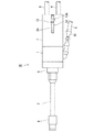
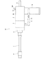
図1に本実施例の噴霧装置10の上方外観の概略図を示す。また、図2に実施例1の噴霧装置10の側方外観の概略図を示す。
FIG. 1 shows a schematic view of the upper appearance of the
この噴霧装置10は、噴霧装置10の本体をなす略円筒形状の胴体部1およびケース2で構成され、この胴体部1に、第1の原材料および第2の原材料を供給するための第1の供給ライン3および第2の供給ライン4が導入される。また、主に洗浄流体を供給する第3の供給ライン5が導入される。胴体部1の上流側には、キャップ6を介して直管部7が接続され、この直管部7の先端に噴霧口としてのノズル部8が一体的に設けられる。第1の供給ライン,第2の供給ラインおよび第3の供給ラインは、胴体部1内において統合され、直管部7に導入される。
The
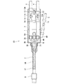
図3に実施例1の噴霧装置10の内部構造を示す部分断面図を示す。
FIG. 3 is a partial cross-sectional view showing the internal structure of the
胴体部1の下流側に一体的に接続されたケース2には、第1の供給ライン3および第2の供給ライン4に設けられた第1の供給バルブ11および第2の供給バルブ12が収容される。第1の原材料および第2の原材料の供給は、第1の供給バルブ11および第2の供給バルブ12の開閉動作により制御することが可能である。
The
こうした構造を有する本発明の噴霧装置において、第1の供給バルブ11および第2の供給バルブ12は、それぞれ個別に原材料の流量を調整するように設けることも可能であるが、噴霧作業時の操作利便性を考慮すると、原材料の供給は、作業時に供給バルブを個々に微調整するような構造とするより、原材料のオンオフを決定する単純な開閉動作であることが好ましい。
In the spraying apparatus of the present invention having such a structure, the
そこで、本実施例の噴霧装置10においては、第1の供給バルブ11および第2の供給バルブ12は、その開閉が一動作で簡単に操作可能であるように、第1の供給バルブ11および第2の供給バルブ12を、1本のレバーで構成された操作部13によって同時開閉することが可能な構成とする。この操作部13は、第1の供給バルブ11および第2の供給バルブ12の弁体と接続してこれを作動させる軸部11Aおよび軸部12Aに直接接続されたドラム部14に一体的に設けられる。一方、操作部13の操作側13Aは、ケース2に設けられたスリット2Aから噴霧装置10の上方に突出しており、この操作側13Aを把持して操作することによりドラム部14が回旋され、第1の供給バルブ11および第2の供給バルブ12が同時に開閉の任意の方向に操作可能なように構成される。
Therefore, in the
一方、第3の供給ライン5には、第3の供給バルブ15が設けられる。第3の供給ライン5は、第1の供給ライン3および第2の供給ライン4とは別に胴体部1の下部側に直接導入される。すなわち、第3の供給バルブ15は、噴霧装置10に洗浄流体を供給する目的上、第1の供給バルブ11および第2の供給バルブ12と独立して操作可能なように設けられる。
On the other hand, the
第1の供給ライン3および第2の供給ライン4は、噴霧装置10の用途や噴霧する材料にもよるが、原材料となる主たる材料の粘性や舗装道路面への塗膜形成量から考慮して、管径15Aから20Aの配管で構成されることが実用上好ましい。また、第1の供給バルブ11および第2の供給バルブ12は、開閉操作をレバー構造の操作部13により行う観点から、供給ラインと同一径の真鍮製やステンレス製のボールバルブが好ましい。また、第1の供給バルブ11および第2の供給バルブ12の耐用圧力および耐用温度等の仕様は、使用する材料の物性および噴霧装置10の使用条件等によって任意に決定してよい。
Although the
胴体部1およびケース2は、第1の供給ライン3および第2の供給ライン4が接続されて第1の供給バルブ11および第2の供給バルブ12が収容されることを考慮して、また皮膜形成作業時の利便性の観点から、内径が約100mm程度、胴体部1とケース2とを合わせた長さが約200mm程度の円管により形成されることが好ましい。胴体部1およびケース2を成す円管の外側面には、操作部13と干渉しない部分、例えば、本実施例のようにスリット2Aの背面側(下方向)にグリップ16が一体的に設けられる。グリップ16は、作業時の噴霧装置10の安定性を向上させるために設けられる把持部であり、噴霧作業時には、作業者は、このグリップ16を把持して噴霧装置10を使用する。
The body part 1 and the
ケース2にキャップ6を介して一体的に設けられた直管部7の内部スペースは、供給された原材料が混合されるチャンバー17であり、チャンバー17で混合されて調製された原液は、このチャンバー17を通じて直管部7の先端に設けられたノズル部8より外部に噴霧されるが、この直管部7には、スタティックミキサ18が内蔵されて、原液をさらに均質な混合物に混合する。
The internal space of the
直管部7は、内部スペースであるチャンバー17にスタティックミキサ18が内蔵され、原材料が十分に混合される程度の長さであれば、その長さは特に限定されないが、直管部7の長さを必要以上に長くすることは、操作性および原液の固着を防止する観点から好ましくない。本発明者らの実施によれば、例えば、エポキシ樹脂を使用する場合、直管部7の長さは、約200mm〜300mm程度であることが好ましい。
The length of the
ノズル部8の形状は、任意に形成することが可能であり、例えば、細長い1本スリットとしたノズル部は、広い面積に皮膜形成材料の原液を噴霧するのに適し、また、円または楕円形状のノズル部としたものは、膜厚の厚い塗膜を形成するのに適する。
The shape of the
一方、第3の供給ライン5は、主として洗浄流体の供給に使用される。本実施例の噴霧装置10において、この第3の供給ライン5は、空気ボンベや溶剤容器等の洗浄流体容器に接続され、第1の供給ライン3および第2の供給ライン4の使用時には、第3の供給バルブ15が閉とされる。噴霧装置10の使用後に、第3の供給バルブ15を開として空気や溶剤等の洗浄流体をチャンバー17に圧送して、ノズル部8の目詰まりやチャンバー17内での原液の固着等を防止する。
On the other hand, the
第1の供給ライン3、第2の供給ライン4および第3の供給ライン5のそれぞれの供給バルブの下流側は、胴体部1内においてカップリングや溶接等の手段による継手3A,継手4Aおよび継手5Aにより適切に配管径が絞られて、それぞれ銅チューブ3B,銅チューブ4Bおよび銅チューブ5Bに接続され、チャンバー17の入口に向けて収束するように配管される。
The downstream side of each supply valve of the
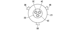
銅チューブ3B,銅チューブ4Bおよび銅チューブ5Bの下流側端部である流体排出口3C,流体排出口4Cおよび流体排出口5Cは、統合されて流体排出部20を成す。図4に流体排出部20をノズル部8側から見た正面図を示す。チャンバー17の入口に原材料および洗浄流体を供給する流体排出部20は、図4に示す正面図のように構成されており、それぞれ第1の原材料、第2の原材料および洗浄流体をチャンバー17に射出するように構成される。
The
この流体排出部20は、キャップ6内に収容されてチャンバー17に流体を排出するが、チャンバー17と流体排出部20との接続部分には、樹脂のパテ等のシール材により気密性が保たれるようにシーリングするシール部21が設けられ、原材料および洗浄流体の胴体部1側への逆流が防止される。
The
胴体部1、ケース2、キャップ6、直管部7、ノズル8を構成する材料としては、防錆性に優れたステンレス製が好ましい。
As a material constituting the body 1, the
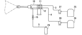
図5に噴霧装置10に原材料を供給するシステムの系統図を示す。
FIG. 5 shows a system diagram of a system for supplying raw materials to the
図5に示すように、第1の供給ライン3および第2の供給ライン4の噴霧装置10に接続された一端と反対側の一端は、それぞれ第1の原材料供給容器25および第2の原材料容器26に接続されており、第1の供給ライン3および第2の供給ライン4にそれぞれ設けられた第1の供給ポンプ27および第2の供給ポンプ28によって、原材料が任意の供給量で噴霧装置10に供給される。あるいは、第1の供給ライン3および第2の供給ライン4にそれぞれ流量調整バルブを設けて、原材料の供給量を調整する構成とすることも可能である。
As shown in FIG. 5, one end of the
すなわち、本実施例の噴霧装置10においては、原材料の供給速度や原材料同士の混合割合の変更は、原材料供給容器側に設けられた供給ポンプ等の手段により実施する。原材料の混合割合は、使用する材料によって異なるが、この実施例の噴霧装置10は、原材料の供給量をポンプ圧によって制御し、噴霧装置10本体における操作系は、供給バルブによる開閉作業のみである。第3の供給ラインは、空気ボンベ29に接続されて、噴霧装置10に洗浄流体を供給する。
That is, in the
一方、実施例2の噴霧装置として、3液混合タイプの材料を噴霧するのに、第3のラインを第3の原材料供給容器に接続して、第3の原材料の供給ラインとして活用することも可能である。 On the other hand, as a spraying apparatus of Example 2, it is also possible to connect a third line to a third raw material supply container to spray a three-component mixed type material and use it as a third raw material supply line. Is possible.
このように、本発明の噴霧装置は、2液混合タイプの材料にも3液混合タイプの材料にも適用可能である。なお、第3の供給ライン5を原材料の供給ラインとして使用した後は、空気ボンベや溶剤容器等の洗浄流体容器に接続し、洗浄流体を流通させてチャンバー17およびノズル部8を洗浄する。あるいは、第3の供給ラインに三方弁等の切換機構を設けて、第3の原材料供給容器につながる配管と、洗浄流体容器につながる配管とを切換可能に構成してもよい。
Thus, the spray device of the present invention can be applied to both a two-liquid mixed type material and a three-liquid mixed type material. After the
本発明の噴霧装置の取扱方法について説明する。 A method for handling the spray device of the present invention will be described.
噴霧作業時には、ケース2と一体に設けられたグリップ16を把持してノズル部8を皮膜形成する対象面に向け、操作部13を開方向に操作して第1の供給バルブ11および第2の供給バルブ12を同時に開とする。
At the time of the spraying operation, the
第1の原材料および第2の原材料は、第1の原材料供給容器25および第2の原材料容器26から、第1の供給ポンプ27および第2の供給ポンプ28の圧力により一定供給量でチャンバー17に供給され、チャンバー17に設けられたスタティックミキサ18により均一な原液に調製されてノズル部8より所望の形状に、例えば、扇状に射出される。
The first raw material and the second raw material are supplied from the first raw
皮膜形成作業を終了するには、操作部13を閉に操作して第1の供給バルブ11および第2の供給バルブ12を同時に閉とし、チャンバー17への原材料の供給をストップする。次に、第3の供給バルブを開とし、洗浄流体を所定の圧力にてチャンバー17に送入し、チャンバー17を洗浄して原液の固着を防止する。
In order to finish the film forming operation, the
また、3種類の原材料を混合するタイプの材料の場合は、第3の供給ライン5を図示しない第3の原材料供給容器に接続し、第1の供給バルブ11,第2の供給バルブ12および第3の供給バルブ15を同時に開とする。
In the case of a material that mixes three kinds of raw materials, the
なお、本実施例の噴霧装置において、3液混合タイプの材料を噴霧する場合には、第1および第2の供給バルブと独立して操作可能な第3の供給バルブを用いる構成としたが、例えば、第1〜第3の供給バルブを全て同時に操作可能に設け、第4の供給バルブを新たに設けて洗浄流体ラインとする構成としても良い。このように、原材料供給用に設けられるバルブの数は、3個以上であっても良く、実施例の噴霧装置に限定されない。 In addition, in the spraying apparatus of the present embodiment, when spraying a three-component mixed type material, the third supply valve that can be operated independently of the first and second supply valves is used. For example, all of the first to third supply valves may be provided so that they can be operated simultaneously, and a fourth supply valve may be newly provided as a cleaning fluid line. Thus, the number of valves provided for raw material supply may be three or more, and is not limited to the spray device of the embodiment.
本発明の噴霧装置は、例えば、道路舗装面に遮熱性を有する樹脂皮膜を形成する噴霧装置として好適に使用されるが、上記目的以外にも、例えば、以下の表1に示すような用途に使用することが可能である。

この表に示すように、本発明の噴霧装置により噴霧可能な材料の例としては、ポリウレタン樹脂、エポキシ樹脂、メタクリル樹脂(MMA)、ポリエステル樹脂等の高分子材料が例示され、用途としては、遮熱皮膜形成以外にも滑り止め塗装や景観塗装、防水、防食ライニング等に使用可能である。また、道路舗装面の他に、駐車場、テニスコート、水道用施設等に対する材料の吹付けにも使用可能である。さらに、ゴムアスファルトのような3液混合型の高分子材料についても適用することが可能である。 As shown in this table, polymer materials such as polyurethane resin, epoxy resin, methacrylic resin (MMA), and polyester resin are exemplified as examples of materials that can be sprayed by the spraying apparatus of the present invention. In addition to thermal film formation, it can be used for anti-slip coating, landscape coating, waterproofing, anticorrosion lining, etc. In addition to road pavement surfaces, it can also be used for spraying materials on parking lots, tennis courts, water supply facilities, and the like. Furthermore, the present invention can also be applied to a three-component mixed polymer material such as rubber asphalt.
以上説明のように、本発明の噴霧装置は、原材料を混合して原液を調整する材料を噴霧する場合に、これらの原材料をノズル部の直前で混合して原液を調製するため、ノズル部や噴霧装置の本体内での材料の固着や目詰まり等の不都合が防止される。 As described above, in the spraying apparatus of the present invention, when the raw materials are mixed to spray the material for adjusting the stock solution, these raw materials are mixed immediately before the nozzle portion to prepare the stock solution. Inconveniences such as material sticking and clogging in the main body of the spraying device are prevented.
また、原材料を供給する第1の供給ラインおよび第2の供給ラインに設けられた第1の供給バルブおよび第2の供給バルブの開閉を操作する操作部を噴霧装置の本体を構成するケースに設けたので、原材料の供給を噴霧装置の本体を把持した状態で原液の噴霧を制御することが可能である。従って、噴霧装置と原材料供給容器との距離を長く取ることが可能となり、また、噴霧装置が小型であるため操作性および作業効率が向上する。 In addition, an operation unit for operating the first supply valve and the second supply valve provided in the first supply line and the second supply line for supplying the raw materials is provided in a case constituting the main body of the spraying device. Therefore, it is possible to control the spraying of the raw solution while holding the supply of the raw materials while holding the main body of the spraying device. Therefore, the distance between the spraying device and the raw material supply container can be increased, and the operability and work efficiency are improved because the spraying device is small.
また、従来の2液混合タイプの噴霧装置は、原材料同士を同圧、等量で衝突混合させなければ、均質な原液の調製が不可能であったが、本発明の噴霧装置によれば、原材料同士を任意の流量および圧力にて供給し、十分に均質な原料を調製することが可能である。 In addition, the conventional two-liquid mixing type spraying device cannot prepare a homogeneous stock solution unless the raw materials are collided and mixed at the same pressure and in the same amount, but according to the spraying device of the present invention, It is possible to prepare raw materials that are sufficiently homogeneous by supplying raw materials at an arbitrary flow rate and pressure.
1 胴体部
2 ケース
2A スリット
3 第1の供給ライン
3A 継手
3B 銅チューブ
3C 流体排出口
4 第2の供給ライン
4A 継手
4C 流体排出口
4B 銅チューブ
5 第3の供給ライン
5A 継手
5B 銅チューブ
5C 流体排出口
6 キャップ
7 直管部
8 ノズル部
10 噴霧装置
11 第1の供給バルブ
12 第2の供給バルブ
13 操作部
13A 操作側
14 ドラム部
15 第3の供給バルブ
16 グリップ
17 チャンバー
18 スタティックミキサ
19 流体排出部
21 シール部
25 第1の原材料供給容器
26 第2の原材料供給容器
27 第1の供給ポンプ
28 第2の供給ポンプ
29 空気ボンベ
DESCRIPTION OF SYMBOLS 1
Claims (8)
Priority Applications (1)
| Application Number | Priority Date | Filing Date | Title |
|---|---|---|---|
| JP2004120700A JP2005296896A (en) | 2004-04-15 | 2004-04-15 | Spray apparatus and handling method of the same |
Applications Claiming Priority (1)
| Application Number | Priority Date | Filing Date | Title |
|---|---|---|---|
| JP2004120700A JP2005296896A (en) | 2004-04-15 | 2004-04-15 | Spray apparatus and handling method of the same |
Publications (1)
| Publication Number | Publication Date |
|---|---|
| JP2005296896A true JP2005296896A (en) | 2005-10-27 |
Family
ID=35329087
Family Applications (1)
| Application Number | Title | Priority Date | Filing Date |
|---|---|---|---|
| JP2004120700A Pending JP2005296896A (en) | 2004-04-15 | 2004-04-15 | Spray apparatus and handling method of the same |
Country Status (1)
| Country | Link |
|---|---|
| JP (1) | JP2005296896A (en) |
Cited By (9)
| Publication number | Priority date | Publication date | Assignee | Title |
|---|---|---|---|---|
| JP2009072690A (en) * | 2007-09-20 | 2009-04-09 | Token Kogyo Kk | Spray apparatus, method for forming coating film and coating film |
| WO2010061704A1 (en) * | 2008-11-26 | 2010-06-03 | 電気化学工業株式会社 | Composition-dispensing device |
| KR101398100B1 (en) | 2013-06-14 | 2014-05-27 | 주식회사 지아이에스이십일 | Underground facilities track indicators paints coated device and methods |
| CN105064183A (en) * | 2015-07-29 | 2015-11-18 | 湖北华舟重工应急装备股份有限公司 | Paving device for hard-pavement paving vehicle |
| CN105499064A (en) * | 2014-09-22 | 2016-04-20 | 汉达精密电子(昆山)有限公司 | Mixed glue control apparatus |
| JP6047256B1 (en) * | 2016-06-28 | 2016-12-21 | 大日本塗料株式会社 | How to paint the road |
| JP2017100104A (en) * | 2015-12-04 | 2017-06-08 | 日本ライナー株式会社 | Heat-shielding paint scattering prevention curing cave with dust collector |
| WO2018127976A1 (en) * | 2017-01-06 | 2018-07-12 | 株式会社ジャムコ | Insulative coating method for sealing carbon-fiber exposed end of composite part using dispenser device |
| JP2021147977A (en) * | 2020-03-23 | 2021-09-27 | 世紀東急工業株式会社 | Manufacturing apparatus of reclaimed heated asphalt mixture and manufacturing method of reclaimed heated asphalt mixture |
-
2004
- 2004-04-15 JP JP2004120700A patent/JP2005296896A/en active Pending
Cited By (14)
| Publication number | Priority date | Publication date | Assignee | Title |
|---|---|---|---|---|
| JP2009072690A (en) * | 2007-09-20 | 2009-04-09 | Token Kogyo Kk | Spray apparatus, method for forming coating film and coating film |
| WO2010061704A1 (en) * | 2008-11-26 | 2010-06-03 | 電気化学工業株式会社 | Composition-dispensing device |
| CN102223955A (en) * | 2008-11-26 | 2011-10-19 | 电气化学工业株式会社 | Composition-dispensing device |
| JP5647004B2 (en) * | 2008-11-26 | 2014-12-24 | 電気化学工業株式会社 | Discharge device and cleaning method of discharge device |
| CN102223955B (en) * | 2008-11-26 | 2015-06-17 | 电气化学工业株式会社 | Composition-dispensing device and cleaning method therefor |
| KR101398100B1 (en) | 2013-06-14 | 2014-05-27 | 주식회사 지아이에스이십일 | Underground facilities track indicators paints coated device and methods |
| CN105499064A (en) * | 2014-09-22 | 2016-04-20 | 汉达精密电子(昆山)有限公司 | Mixed glue control apparatus |
| CN105064183A (en) * | 2015-07-29 | 2015-11-18 | 湖北华舟重工应急装备股份有限公司 | Paving device for hard-pavement paving vehicle |
| JP2017100104A (en) * | 2015-12-04 | 2017-06-08 | 日本ライナー株式会社 | Heat-shielding paint scattering prevention curing cave with dust collector |
| JP6047256B1 (en) * | 2016-06-28 | 2016-12-21 | 大日本塗料株式会社 | How to paint the road |
| WO2018127976A1 (en) * | 2017-01-06 | 2018-07-12 | 株式会社ジャムコ | Insulative coating method for sealing carbon-fiber exposed end of composite part using dispenser device |
| JP6367487B1 (en) * | 2017-01-06 | 2018-08-01 | 株式会社ジャムコ | Insulation coating method for sealing carbon fiber exposed end of composite material part using dispenser device |
| US10618068B2 (en) | 2017-01-06 | 2020-04-14 | Jamco Corporation | Method for applying insulative coating to carbon-fiber exposed end of composite material part using dispenser device |
| JP2021147977A (en) * | 2020-03-23 | 2021-09-27 | 世紀東急工業株式会社 | Manufacturing apparatus of reclaimed heated asphalt mixture and manufacturing method of reclaimed heated asphalt mixture |
Similar Documents
| Publication | Publication Date | Title |
|---|---|---|
| US20220297143A1 (en) | Low pressure plural component foam spray system | |
| US8911138B2 (en) | Fluid dispensing system and method for concrete mixer | |
| KR101828313B1 (en) | Waterproof injection device of building | |
| US20220281735A1 (en) | Manifold and Fluid Dispensing Systems | |
| JP2005296896A (en) | Spray apparatus and handling method of the same | |
| US20200239699A1 (en) | Cement resin hybrid paint and coating | |
| WO2008039436A3 (en) | Spray gun | |
| JP2001248164A (en) | Construction method for spraying mixture and apparatus therefor | |
| JP2001321701A (en) | Spray gun | |
| US20180272564A1 (en) | Flex-Cure Pneumatically Applied Wet Blanket | |
| JP4911554B2 (en) | Asphalt coating material spraying equipment | |
| CA2528600A1 (en) | Dispensing apparatus | |
| WO2004067187A1 (en) | Apparatus for the gunning of a refractory material and nozzles for same | |
| KR101132326B1 (en) | Spray system | |
| JP4356824B2 (en) | Spraying material spraying method and material conveying method in spraying apparatus | |
| JP4754345B2 (en) | Spraying device, spraying method and repair method using the same | |
| CN207913979U (en) | A kind of rapid hardening water-repellent paint spray equipment | |
| KR200348548Y1 (en) | 2 comp cold plastic useing lane applycation device | |
| US7854397B2 (en) | Long throw shotcrete nozzle | |
| SU1180445A1 (en) | Guniting and shotcreting apparatus | |
| WO2007023885A1 (en) | Sulfur material spraying apparatus | |
| KR101321568B1 (en) | Spray apparatus of polymer resin with heating | |
| JP2003293585A (en) | Spraying method for mixture containing quick-setting admixture and its device | |
| SU1105653A1 (en) | Shotcreting apparatus | |
| KR20090019084A (en) | Construction device of high toughness fire-retardant mortar containing a large amount of short fibers |
Legal Events
| Date | Code | Title | Description |
|---|---|---|---|
| A621 | Written request for application examination |
Effective date: 20051128 Free format text: JAPANESE INTERMEDIATE CODE: A621 |
|
| A977 | Report on retrieval |
Effective date: 20081006 Free format text: JAPANESE INTERMEDIATE CODE: A971007 |
|
| A131 | Notification of reasons for refusal |
Effective date: 20081014 Free format text: JAPANESE INTERMEDIATE CODE: A131 |
|
| A02 | Decision of refusal |
Free format text: JAPANESE INTERMEDIATE CODE: A02 Effective date: 20090224 |