JP2005296985A - Sheet crown and shape control method in sheet rolling - Google Patents
Sheet crown and shape control method in sheet rolling Download PDFInfo
- Publication number
- JP2005296985A JP2005296985A JP2004114999A JP2004114999A JP2005296985A JP 2005296985 A JP2005296985 A JP 2005296985A JP 2004114999 A JP2004114999 A JP 2004114999A JP 2004114999 A JP2004114999 A JP 2004114999A JP 2005296985 A JP2005296985 A JP 2005296985A
- Authority
- JP
- Japan
- Prior art keywords
- plate
- crown
- shape
- plate crown
- target
- Prior art date
- Legal status (The legal status is an assumption and is not a legal conclusion. Google has not performed a legal analysis and makes no representation as to the accuracy of the status listed.)
- Granted
Links
Images

Landscapes
- Control Of Metal Rolling (AREA)
Abstract
【課題】設定計算時に板クラウンおよび板形状設定計算精度を良好にし、熱延鋼板の圧延後の目標板クラウンおよび板形状を得るための板クラウンおよび形状制御方法を提供する.
【解決手段】複数の圧延スタンドを有する熱間連続圧延機列で、最終スタンド出側で目標とする板クラウンおよび板形状を得るための板クラウンおよび板形状設定計算を行う方法において、最終スタンド出側の初期設定の目標板クラウンおよび板形状を基に、板クラウンおよび板形状設定計算を行い、ついで前記設定計算で算出された板クラウンと初期設定の目標とする板クラウンとの誤差を算出し、前記誤差を減少させる方向に、目標とする最終スタンド出側の目標板形状を変更し、板クラウン形状制御装置の設定値を算出することを特徴とする板圧延における板クラウンおよび形状制御方法。
【選択図】図1
The present invention provides a plate crown and shape control method for improving the accuracy of calculation of plate crown and plate shape at the time of setting calculation and obtaining a target plate crown and plate shape after rolling a hot-rolled steel sheet.
In a hot continuous rolling mill row having a plurality of rolling stands, a method for calculating a plate crown and a plate shape to obtain a target plate crown and plate shape on the final stand exit side is provided. The plate crown and plate shape setting calculation is performed based on the default target plate crown and plate shape on the side, and then the error between the plate crown calculated in the setting calculation and the target plate crown of the initial setting is calculated. A plate crown and shape control method in plate rolling, wherein a target plate shape on the final stand exit side is changed in a direction to reduce the error, and a set value of a plate crown shape control device is calculated.
[Selection] Figure 1
Description
本発明は、複数の圧延スタンドを有する熱間連続圧延機列で、最終スタンド出側で目標とする板クラウンおよび板形状を得るための板クラウンおよび板形状設定計算を行う方法に関する。 The present invention relates to a method for performing plate crown and plate shape setting calculation for obtaining a target plate crown and plate shape on the final stand exit side in a hot continuous rolling mill having a plurality of rolling stands.
圧延材の板クラウンおよび板形状を計算機制御によって、圧延後の目標板クラウンおよび板形状を達成するためには、圧延条件が与えられた時点で、先ず、その圧延で生じる板クラウンおよび板形状を実用的精度で表現するモデル、すなわち板クラウン形状予測モデルが必要となる。ここで、板形状とは中伸びまたは端伸びのことを指す。このモデルは、圧延現象を表現する物理モデルとして、たとえば、特許文献1で開示されている『圧延制御方法』が知られている。この方法では、ロール変形を代表するパラメータとして、圧延材とワークロールとの間の幅方向荷重分布が一様である場合に実現される板クラウン定義点位置での板クラウンをメカニカル板クラウンCとして定義している。圧延条件によって計算されるメカニカル板クラウンCは、ミル形式によって異なるが、たとえば、次式のように計算されることが知られている。
C = AP・P +AF・F +Co (1)
ここで、Pは圧延荷重、Fはワークロールベンディング力、Coはロールプロフィルの影響項、AP、AFはミル形式、ミルディメンジョン、圧延材板幅などの圧延条件の関数として求められるモデル係数である。
In order to achieve the target plate crown and plate shape after rolling by computer control of the plate crown and plate shape of the rolled material, at the time when rolling conditions are given, the plate crown and plate shape generated by the rolling are first determined. A model expressed with practical accuracy, that is, a plate crown shape prediction model is required. Here, the plate shape indicates middle elongation or end elongation. As this model, for example, a “rolling control method” disclosed in
C = A P · P + A F · F + Co (1)
Here, P is a rolling load, F is a work roll bending force, Co is an influence term of a roll profile, A P and A F are model coefficients obtained as a function of rolling conditions such as a mill type, a mill dimension, and a rolled sheet width. It is.
このメカニカル板クラウンCは、圧延機の変形特性のみで決まる変形量であるが、実圧延での幅方向荷重分布は入側板クラウンや圧延材の幅方向メタルフローなどに起因する材料変形特性によって様々に変化することから、出側板クラウンChは、メカニカル板クラウンには一致せず、一般的に次式で表される。
Ch =(1−η) C+η(1−r) CH (2)
ここで、ηはクラウン比率遺伝係数、rは圧下率、CHは入側板クラウンである。
また、複数の圧延スタンドを有する熱間連続圧延機列で、最終スタンドの目標板クラウンおよび板形状を達成するための最適スケジュール計算、すなわち上述したメカニカル板クラウン、上記関係式と圧延材の板形状限界(中伸び限界または端伸び限界)を考慮して、板クラウン形状制御装置における制御量を計算する方法が特許文献2に開示されている。
ここで、上記制御装置とは、たとえばワークロールベンダ装置、ペアクロス装置、6Hiミルの中間ロールシフト装置など当該スタンドで板クラウンおよび板形状を変更できる制御装置である。すなわち、この計算方法には、実圧延操業で与えられた最終スタンド出側の目標板クラウンおよび板形状を達成し、かつ各圧延スタンド出側での板形状限界を考慮した最適な各スタンド出側の板クラウンおよび板形状を算出する方法が記載されている。
This mechanical sheet crown C is a deformation amount determined only by the deformation characteristics of the rolling mill, but the width direction load distribution in actual rolling varies depending on the material deformation characteristics caused by the width of the inlet side sheet crown and the width direction metal flow of the rolled material. since the change, delivery side crown C h does not match the mechanical strip crown, it is generally expressed by the following equation.
C h = (1-η) C + η (1-r) C H (2)
Here, η is a crown ratio genetic coefficient, r is a rolling reduction, and C H is an entrance plate crown.
Further, in a hot continuous rolling mill row having a plurality of rolling stands, the optimum schedule calculation for achieving the target plate crown and plate shape of the final stand, that is, the mechanical plate crown described above, the above relational expression and the plate shape of the rolled
Here, the control device is a control device that can change the plate crown and plate shape with the stand, such as a work roll bender device, a pair cross device, a 6Hi mill intermediate roll shift device, and the like. That is, this calculation method achieves the target plate crown and plate shape on the final stand delivery side given in the actual rolling operation, and considers the plate shape limit on each rolling stand delivery side, and optimal stand delivery side Describes a method for calculating the plate crown and plate shape.
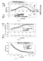
図4には、従来技術において、最終スタンド出側で目標とする板クラウンが達成できなかった例を示す。従来技術において、図4(b)に示すように、最終スタンドのワークロールベンダがインクリース最大値になり、かつ図4(a)に示すように、最終スタンド前方のスタンドで板形状が端伸び限界の設定計算になった場合、図4(b)に示すように最終スタンドより前方のスタンド(以下、「最終スタンド前方スタンド」という)のクラウン制御能力(インクリースベンダ能力)があるにも関わらず、それを使用できず、図4(c)に示すように、目標とする板クラウンが達成不可能になってしまっていた。すなわち、上述したような場合、最終スタンド出側の目標とする板形状は達成可能であるが、目標とする板クラウンを達成できないという問題があった。
本発明は、上述した従来技術の問題を解決し、設定計算時に板クラウンおよび板形状設定計算精度を良好にし、熱延鋼板の圧延後の目標板クラウンおよび板形状を得るための板クラウンおよび形状制御方法を提供することを目的としている。 The present invention solves the above-mentioned problems of the prior art, improves the plate crown and plate shape setting calculation accuracy at the time of setting calculation, and obtains the target plate crown and plate shape after rolling of the hot-rolled steel sheet. It aims to provide a control method.
上記目的を達成するために本発明の要旨とするところは、
(1)複数の圧延スタンドを有する熱間連続圧延機列で、最終スタンド出側で目標とする板クラウンおよび板形状を得るための板クラウンおよび板形状設定計算を行う方法において、最終スタンド出側の初期設定の目標板クラウンおよび板形状を基に、板クラウンおよび板形状設定計算を行い、ついで前記設定計算で算出される最終スタンド出側板クラウンと初期設定の目標とする板クラウンとの誤差を算出し、前記誤差を減少させる方向に目標とする最終スタンド出側の板形状を変更し、板クラウン形状制御装置の設定値を算出することを特徴とする板圧延における板クラウンおよび形状制御方法である。
(2)また、厚板圧延の仕上圧延機で、最終パス出側で目標とする板クラウンおよび板形状を得るための板クラウンおよび板形状設定計算を行う方法において、最終パス出側の初期設定の目標板クラウンおよび板形状を基に、板クラウンおよび板形状設定計算を行い、ついで前記設定計算で算出される最終パス出側板クラウンと初期設定の目標とする板クラウンとの誤差を算出し、前記誤差を減少させる方向に目標とする最終パス出側の板形状を変更し、板クラウン形状制御装置の設定値を算出することを特徴とする板圧延における板クラウンおよび形状制御方法である。
(3)また、目標とする最終スタンドまたは最終パスの板形状の変更量に許容範囲を設けることを特徴とする特許請求項1または2記載の板圧延における板クラウンおよび板形状制御方法である。
In order to achieve the above object, the gist of the present invention is as follows.
(1) In a hot continuous rolling mill row having a plurality of rolling stands, in the method of calculating the plate crown and plate shape to obtain the target plate crown and plate shape on the final stand exit side, the final stand exit side Based on the initially set target plate crown and plate shape, the plate crown and plate shape setting calculation is performed, and then the error between the final stand exit side plate crown calculated by the setting calculation and the initially set target plate crown is calculated. A plate crown and shape control method in plate rolling, characterized in that the plate shape on the final stand exit side is changed in a direction to reduce the error and the set value of the plate crown shape control device is calculated. is there.
(2) In addition, in the method of performing plate crown and plate shape setting calculation to obtain the target plate crown and plate shape on the final pass exit side in the finish rolling mill for thick plate rolling, initial setting on the final pass exit side Based on the target plate crown and plate shape, the plate crown and plate shape setting calculation is performed, and then the error between the final pass exit side plate crown calculated in the setting calculation and the initially set target plate crown is calculated, A plate crown and shape control method in plate rolling, wherein a target plate shape on the final pass exit side is changed in a direction to reduce the error, and a set value of a plate crown shape control device is calculated.
(3) The plate crown and plate shape control method in plate rolling according to
以上説明してきたように、本発明を適用すれば、従来技術に比べて、最終スタンドまたは最終パス出側の目標とする板形状設定起因で、目標とする板クラウンが達成できないという不具合を最小限にすることができ、熱延鋼板の目標とする板クラウンおよび形状を安定的に提供することができる。 As described above, when the present invention is applied, the problem that the target plate crown cannot be achieved due to the target plate shape setting on the final stand or the final pass exit side is minimized as compared with the prior art. Therefore, the target plate crown and shape of the hot-rolled steel plate can be stably provided.
特開文献2に記載されている従来技術の場合、最終スタンドの目標とする板形状を予め設定し、それを加味して最終スタンドの目標板クラウンを達成し得る板クラウンスケジュールが計算されている。しかしながら、[背景技術]でも述べたように、図4(b)に示すように、最終スタンドのワークロールベンダがインクリース最大値になり、かつ図4(a)に示すように、最終スタンド前方スタンドで板形状が端伸び限界の設定計算になった場合、図4(b)に示すように、最終スタンド前方スタンドのクラウン制御能力(インクリースベンダ能力)があるが、それを使用すると、板形状限界を超えてしまうため、その能力を最大限に有効利用できず、図4(c)に示すように、目標とする板クラウン(より低クラウン側)が達成不可能になってしまっていた。 In the case of the prior art described in Japanese Patent Laid-Open Publication No. 2003-228620, a plate crown schedule is calculated in which the target plate crown of the final stand is achieved by setting the target plate shape of the final stand in advance. . However, as described in [Background Art], as shown in FIG. 4 (b), the work roll vendor of the final stand becomes the maximum value of the increment, and as shown in FIG. When the plate shape is calculated to set the end elongation limit at the stand, as shown in FIG. 4 (b), there is a crown control capability (increase vendor capability) of the stand ahead of the final stand. Since the shape limit is exceeded, the capacity cannot be utilized to the maximum extent, and the target plate crown (lower crown side) cannot be achieved as shown in FIG. 4 (c). .
ところで、上述した目標とする板クラウン(低クラウン側)を得るためには、図4(b)に示した最終スタンド前方スタンドのワークロールベンダ設定値をさらにインクリース側へ設定できれば、目標板クラウンに達成可能、またはそれに近づけることが可能となる。しかしながら、従来技術では、たとえば、図4(b)に示したF6スタンドのワークロールベンダ値をインクリース側へ変更した場合、当該スタンド出側の板クラウンは小さくなり、そのため、最終スタンド出側形状が目標板形状より端伸び側になり、従来技術では目標とする板形状が達成できないことがわかる。また、図4(b)に示したF5スタンドのワークロールベンダ値をインクリース側に変更した場合、上述した同様の理由で、F6スタンド出側の板形状は、さらに端伸び側になり、この場合、図4(b)からもわかるようにF6スタンド出側の板形状限界を超えてしまうことになる。すなわち、従来技術による設定計算ではこれ以上低クラウンに設定することができなかった。上記には、低クラウン側について述べてきたが、大クラウン側の設定でも上記と同様な設定(板形状は反対側)になった場合にも、従来技術では、目標とする板クラウンは得ることができなかった。 By the way, in order to obtain the target plate crown (low crown side) described above, if the work roll bender set value of the stand in front of the final stand shown in FIG. Can be achieved or approached. However, in the prior art, for example, when the work roll bender value of the F6 stand shown in FIG. 4 (b) is changed to the increase side, the plate crown on the stand exit side becomes smaller, so that the shape of the final stand exit side is reduced. Is on the end extension side of the target plate shape, and it can be seen that the target plate shape cannot be achieved with the prior art. In addition, when the work roll vendor value of the F5 stand shown in FIG. 4B is changed to the increase side, the plate shape on the F6 stand exit side further becomes the end extension side for the same reason as described above. In this case, as can be seen from FIG. 4B, the plate shape limit on the F6 stand exit side is exceeded. That is, in the setting calculation according to the conventional technique, it was not possible to set a lower crown any more. Although the low crown side has been described above, the target plate crown can be obtained with the conventional technology even when the large crown side is set to the same setting as above (the plate shape is the opposite side). I could not.
一方、圧延操業中の最終スタンドの板形状は、上述した目標設定形状の前後(許容範囲内)であれば、通板トラブルになることはなく、操業上問題がないことを発明者らは知見していた。そこで、発明者らは、上述した問題で目標とする板クラウンを実現不可能な場合(低クラウンが実現できない場合)において、最終スタンド出側の目標板形状を変更することを考えた。
先ず、最終スタンド出側板形状を中伸び形状にすることを考える。上述した問題の場合、最終スタンドのワークロールベンダ設定値はインクリース最大値となっているため、上記形状を得るためには、入側板クラウンを大きくする必要がある。しかしながら、入側板クラウンを大きくすれば、式(2)からもわかるように出側板クラウンも大きくなってしまい、低クラウンを実現することは不可能となる。
On the other hand, the inventors have found that if the plate shape of the final stand during the rolling operation is before and after the above-mentioned target setting shape (within the allowable range), there will be no plate-feeding trouble and there will be no operational problems. Was. Therefore, the inventors have considered changing the target plate shape on the final stand exit side when the target plate crown cannot be realized due to the above-described problem (when the low crown cannot be realized).
First, let us consider making the final stand outlet side plate shape into a middle stretched shape. In the case of the above-described problem, the work roll vendor setting value of the final stand is the maximum value of the ink lease, and therefore it is necessary to enlarge the entrance side plate crown in order to obtain the above shape. However, if the entry-side plate crown is increased, the exit-side plate crown also becomes larger as can be seen from the equation (2), and it is impossible to realize a low crown.
つぎに、最終スタンド出側板形状を端伸び形状にすることを考える。最終スタンドのワークロールベンダ設定値を小さくすれば(インクリースをディクリース方向に変更)、当該スタンド出側形状は端伸び形状になるが、板クラウンは大きくなり、この場合も低クラウンを実現することが不可能となる。
また、最終スタンド出側板形状を端伸びにする上記以外の方法として、最終スタンド入側板クラウンを小さくすればよいことが考えられる。この場合、最終スタンド出側板形状が端伸び形状になり、式(2)からもわかるように、最終スタンド出側板クラウンも小さくなる。すなわち、最終スタンド前方スタンドのワークロールベンダがインクリース方向に余裕がある場合、最終スタンド出側の目標形状を変更すれば、従来技術では達成できなかった目標板クラウンを実現できることを見出した。
Next, let us consider making the final stand outlet side plate shape into an end-extended shape. If the work roll vendor setting value of the final stand is reduced (change the increment to the decrease direction), the stand-out side shape becomes an end-extended shape, but the plate crown becomes large, and in this case also a low crown is realized. It becomes impossible.
Further, as a method other than the above in which the final stand exit side plate shape is extended to the end, it is conceivable that the final stand entrance side plate crown may be made smaller. In this case, the final stand exit side plate shape becomes an end extension shape, and the final stand exit side plate crown becomes smaller as can be seen from the equation (2). That is, when the work roll bender of the stand before the final stand has a margin in the ink lease direction, it has been found that if the target shape on the final stand exit side is changed, a target plate crown that could not be achieved by the prior art can be realized.
そこで、発明者らは最終スタンド出側目標板形状に、通板トラブルが生じない範囲で、板形状の変更許容範囲を設け、その許容範囲で板クラウン形状スケジュール計算を実施すれば、目標とする板クラウンを実現、もしくはその近傍にまで達成することができることを見出した。本発明の具体的な計算方法を実施例の欄で詳しく説明するものとする。
また、上記最終スタンドの目標板形状およびその許容範囲は、圧延操業上通板トラブルが発生しない範囲で設定すればよい。その設定値は、たとえば出側板厚、板幅、圧下率、ロール径などの圧延因子でモデル化した値を使用してもよい。
また、本発明は、複数の圧延スタンドを有する熱間圧延機列のみならず、厚板のようなリバースミルにも適用できる。
Therefore, the inventors set a plate shape change allowable range in the final stand exit side target plate shape within a range that does not cause a plate passing trouble, and if the plate crown shape schedule calculation is performed within the allowable range, the target is set. It has been found that a plate crown can be realized or achieved in the vicinity thereof. The specific calculation method of the present invention will be described in detail in the section of the examples.
Further, the target plate shape of the final stand and its allowable range may be set within a range that does not cause a trouble with plate passing during rolling operation. As the set value, for example, a value modeled by a rolling factor such as a delivery side plate thickness, a plate width, a rolling reduction, and a roll diameter may be used.
The present invention can be applied not only to a hot rolling mill having a plurality of rolling stands but also to a reverse mill such as a thick plate.
本発明を複数の圧延スタンドを有する熱間連続圧延機列で適用した具体事例を以下に示す。発明者らは、最終スタンド出側での目標板クラウンおよび形状を達成するための各スタンドにおける最適板クラウン形状スケジュール計算手法は、基本的には特許文献2に開示されている従来技術を用い、本発明を加味した板クラウンおよび板形状設定計算ロジックを構築した。
Specific examples in which the present invention is applied to a hot continuous rolling mill having a plurality of rolling stands are shown below. The inventors basically use the conventional technique disclosed in
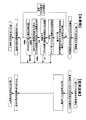
本発明と従来技術の設定計算手順の一例を図2に示す。図2に示すように、従来技術では判定基準になっていない最終スタンド出側目標板クラウンに達したかを判定し、達成していない場合、最終スタンドの目標形状を[発明を実施するための最良の形態]でも述べたように、目標板クラウンを達成する方向に、最終スタンド目標板形状の変更を実施し、再度、最適板クラウン形状スケジュール計算を行えばよい。また、最終スタンド出側板形状の変更量であるが、たとえば、上記変更方向に徐々に変更していけばよい。その際、たとえば収束の判定方法として、一般的に用いられる『はさみ打ち法』や『直接代入法』など数学的に、順次、解に近づけていく方法を採用してもよい。また、図2に示すように、収束判定として、現在の最終スタンド板形状と前回のそれとの差が収束判定範囲内であれば収束したとしてもよい。その際、上記収束判定範囲は予め設定しておけばよい。また、本発明は収束計算を必要とするため、設定計算時間に問題(計算時間が長くなりすぎる)がある場合には、予め最大修正回数を設けておけばよい。 An example of the setting calculation procedure of the present invention and the prior art is shown in FIG. As shown in FIG. 2, it is determined whether or not the final stand exit side target plate crown that has not been judged in the prior art has been reached. If not, the target shape of the final stand is set to [for carrying out the invention]. As described in [Best Mode], the final stand target plate shape may be changed in a direction to achieve the target plate crown, and the optimal plate crown shape schedule may be calculated again. Moreover, although it is the amount of change of the final stand exit side plate shape, for example, it may be changed gradually in the change direction. In this case, for example, as a method for determining convergence, a method of gradually approaching the solution in a mathematical manner such as a commonly used “scissors method” or “direct substitution method” may be employed. Further, as shown in FIG. 2, the convergence determination may be made as long as the difference between the current final stand plate shape and the previous shape is within the convergence determination range. At this time, the convergence determination range may be set in advance. Further, since the present invention requires a convergence calculation, if there is a problem in the setting calculation time (the calculation time becomes too long), the maximum number of corrections may be set in advance.
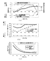
図1および図3には、本発明の実施形態の一例を示す。発明者らは、 複数の圧延スタンドを有する熱間連続圧延機列で本発明を実施した。その際、各スタンドの板形状限界を図1に示すように、たとえば急峻度として±1.5%、目標板クラウンを板端から25mm点位置で0.025mm、目標とする初期設定の最終スタンド出側板形状をゼロとし、本発明の板形状設定許容範囲を急峻度として±1.25%として適用した。
図1に示すように、上記条件において、従来技術では、目標とする板クラウンは達成不可能であることがわかる。このような場合、最終スタンド出側の目標とする板形状の変更を実施し(今回:急峻度0.110%へ変更)、最終スタンド前方のワークロールベンダ制御能力を有効に利用した板クラウンスケジュールを実施することで、図1に示すように、目標とする板クラウンを実現可能になっていることがわかる。
1 and 3 show an example of an embodiment of the present invention. The inventors have implemented the present invention with a hot continuous rolling mill having a plurality of rolling stands. At that time, as shown in Fig. 1, the plate shape limit of each stand is ± 1.5% as the steepness, for example, the target plate crown is 0.025mm at the 25mm point position from the plate end, the target final plate shape of the final stand exit side The plate shape setting allowable range of the present invention was applied as steepness of ± 1.25%.
As shown in FIG. 1, it can be seen that the target plate crown cannot be achieved by the conventional technique under the above conditions. In such a case, change the target plate shape on the exit side of the final stand (this time: change to steepness 0.110%), and execute the plate crown schedule that effectively uses the work roll vendor control ability in front of the final stand By doing so, as shown in FIG. 1, it can be seen that the target plate crown can be realized.
また、最終スタンド出側での目標板形状の変更方向は、たとえば上述の場合、図1に示すように、最終スタンド出側形状は端伸び方向へ、たとえば図3に示すように、最終スタンドのワークロールベンダ値に余裕がある場合(前スタンドでは設定限界値)は、中伸び方向へ修正することが最適である。すなわち、図1、3に示すように、最終スタンドを含め後段の制御能力を最大限に活用し、目標とする板クラウンを達成できる方向へ最終スタンドの板形状を変更すればよいことがわかる。
本発明は、低クラウン側への修正について説明してきたが、大クラウン側への修正が必要な場合、上述した方法と逆の設定を行えば実現可能であることは言うまでもない。
また、本発明は、複数の圧延スタンドを有する熱間圧延機列のみならず、厚板のようなリバースミルにも適用できる。
In addition, the direction of changing the target plate shape at the final stand exit side is, for example, as shown in FIG. 1, as shown in FIG. 1, the final stand exit side shape is the end extension direction, for example, as shown in FIG. When there is a margin in the work roll vendor value (setting limit value for the front stand), it is optimal to correct it in the middle extension direction. That is, as shown in FIGS. 1 and 3, it is understood that it is sufficient to change the plate shape of the final stand in a direction in which the target plate crown can be achieved by making maximum use of the control ability of the subsequent stage including the final stand.
Although the present invention has been described with respect to correction to the low crown side, it is needless to say that if correction to the large crown side is necessary, it can be realized by performing a setting reverse to the above-described method.
The present invention can be applied not only to a hot rolling mill having a plurality of rolling stands but also to a reverse mill such as a thick plate.
Claims (2)
最終スタンド出側の初期設定の目標板クラウンおよび板形状を基に、板クラウンおよび板形状設定計算を行い、ついで前記設定計算で算出される最終スタンド出側板クラウンと初期設定の目標とする板クラウンとの誤差を算出し、前記誤差を減少させる方向に目標とする最終スタンド出側の目標板形状を変更し、板クラウン形状制御装置の設定値を算出することを特徴とする板圧延における板クラウンおよび形状制御方法。 In a method for performing plate crown and plate shape setting calculation to obtain a target plate crown and plate shape on the final stand exit side in a hot continuous rolling mill row having a plurality of rolling stands,
Based on the initially set target plate crown and plate shape on the final stand exit side, the plate crown and plate shape setting calculation is performed, and then the final stand exit side plate crown calculated by the above setting calculation and the initial set target plate crown And calculating a set value of a plate crown shape control device by changing a target plate shape on the final stand exit side in a direction to reduce the error, and calculating a set value of the plate crown shape control device And shape control method.
最終パス出側の初期設定の目標板クラウンおよび板形状を基に、板クラウンおよび板形状設定計算を行い、ついで前記設定計算で算出される最終パス出側板クラウンと初期設定の目標とする板クラウンとの誤差を算出し、前記誤差を減少させる方向に目標とする最終パス出側の目標板形状を変更し、板クラウン形状制御装置の設定値を算出することを特徴とする板圧延における板クラウンおよび形状制御方法。
In the method of performing plate crown and plate shape setting calculation to obtain the target plate crown and plate shape on the final pass exit side in the finish rolling mill for thick plate rolling,
Based on the initially set target crown and plate shape on the final pass exit side, the plate crown and plate shape setting calculation is performed, and then the final pass exit plate crown calculated by the above setting calculation and the initial set target plate crown And calculating a set value of the plate crown shape control device, changing the target plate shape on the final pass exit side in a direction to reduce the error, and calculating a set value of the plate crown shape control device And shape control method.
Priority Applications (1)
| Application Number | Priority Date | Filing Date | Title |
|---|---|---|---|
| JP2004114999A JP4276571B2 (en) | 2004-04-09 | 2004-04-09 | Sheet crown and shape control method in sheet rolling |
Applications Claiming Priority (1)
| Application Number | Priority Date | Filing Date | Title |
|---|---|---|---|
| JP2004114999A JP4276571B2 (en) | 2004-04-09 | 2004-04-09 | Sheet crown and shape control method in sheet rolling |
Publications (2)
| Publication Number | Publication Date |
|---|---|
| JP2005296985A true JP2005296985A (en) | 2005-10-27 |
| JP4276571B2 JP4276571B2 (en) | 2009-06-10 |
Family
ID=35329165
Family Applications (1)
| Application Number | Title | Priority Date | Filing Date |
|---|---|---|---|
| JP2004114999A Expired - Fee Related JP4276571B2 (en) | 2004-04-09 | 2004-04-09 | Sheet crown and shape control method in sheet rolling |
Country Status (1)
| Country | Link |
|---|---|
| JP (1) | JP4276571B2 (en) |
Cited By (6)
| Publication number | Priority date | Publication date | Assignee | Title |
|---|---|---|---|---|
| CN102658297A (en) * | 2012-04-28 | 2012-09-12 | 北京科技大学 | Self-learning method for improving quality of first band steel plate shape with changed specification |
| CN104511482A (en) * | 2013-09-26 | 2015-04-15 | 宝山钢铁股份有限公司 | Hot rolled strip steel convexity control method |
| CN104511483A (en) * | 2013-09-26 | 2015-04-15 | 宝山钢铁股份有限公司 | Hot-rolled strip shape compensation rolling method |
| CN104858243A (en) * | 2014-02-26 | 2015-08-26 | 宝山钢铁股份有限公司 | Wide and thin plate plane shape control method based on convexity control |
| CN105327946A (en) * | 2015-11-11 | 2016-02-17 | 北京首钢股份有限公司 | Convexity effectiveness judging method and system for feedback calculation of plate shape model |
| CN111889514A (en) * | 2020-07-27 | 2020-11-06 | 苏州博恩普特测控科技有限公司 | Optimized calculation method for cold-rolled plate shape target curve |
-
2004
- 2004-04-09 JP JP2004114999A patent/JP4276571B2/en not_active Expired - Fee Related
Cited By (9)
| Publication number | Priority date | Publication date | Assignee | Title |
|---|---|---|---|---|
| CN102658297A (en) * | 2012-04-28 | 2012-09-12 | 北京科技大学 | Self-learning method for improving quality of first band steel plate shape with changed specification |
| CN104511482A (en) * | 2013-09-26 | 2015-04-15 | 宝山钢铁股份有限公司 | Hot rolled strip steel convexity control method |
| CN104511483A (en) * | 2013-09-26 | 2015-04-15 | 宝山钢铁股份有限公司 | Hot-rolled strip shape compensation rolling method |
| CN104858243A (en) * | 2014-02-26 | 2015-08-26 | 宝山钢铁股份有限公司 | Wide and thin plate plane shape control method based on convexity control |
| CN104858243B (en) * | 2014-02-26 | 2017-02-22 | 宝山钢铁股份有限公司 | Wide and thin plate plane shape control method based on convexity control |
| CN105327946A (en) * | 2015-11-11 | 2016-02-17 | 北京首钢股份有限公司 | Convexity effectiveness judging method and system for feedback calculation of plate shape model |
| CN105327946B (en) * | 2015-11-11 | 2017-10-03 | 北京首钢股份有限公司 | A kind of shape models feed back the decision method and system of calculating convexity validity |
| CN111889514A (en) * | 2020-07-27 | 2020-11-06 | 苏州博恩普特测控科技有限公司 | Optimized calculation method for cold-rolled plate shape target curve |
| CN111889514B (en) * | 2020-07-27 | 2022-05-17 | 苏州博恩普特测控科技有限公司 | Optimized calculation method for cold-rolled plate shape target curve |
Also Published As
| Publication number | Publication date |
|---|---|
| JP4276571B2 (en) | 2009-06-10 |
Similar Documents
| Publication | Publication Date | Title |
|---|---|---|
| US8185232B2 (en) | Learning method of rolling load prediction for hot rolling | |
| CN110052497B (en) | Complete set of roll shape and plate shape control method for hot continuous rolling finishing mill unit | |
| JP4948301B2 (en) | Shape control method in cold rolling | |
| JP4276571B2 (en) | Sheet crown and shape control method in sheet rolling | |
| JPWO2008129634A1 (en) | Thickness control device for reverse rolling mill | |
| JP3253013B2 (en) | Strip crown and shape control method in hot rolling | |
| CN112916614A (en) | Flat rolling method for 7-8mm steel plate with limited length | |
| JP4701762B2 (en) | Hot rolled steel sheet rolling method | |
| US11938528B2 (en) | Method for ascertaining control variables for active profile and flatness control elements for a rolling stand and profile and average flatness values for hot-rolled metal strip | |
| JP5862248B2 (en) | Metal strip rolling method | |
| JP4814836B2 (en) | Hot rolling method in sheet rolling | |
| JP4330134B2 (en) | Shape control method in cold rolling | |
| KR100931541B1 (en) | Rolled plate shape control method | |
| JPH08117829A (en) | Cold rolling method for thin steel sheet | |
| JP6232193B2 (en) | Shape control method and shape control method in cold rolling | |
| JP2007203303A (en) | Shape control method in cold rolling | |
| JP4617929B2 (en) | Hot rolled steel sheet rolling method | |
| CN112122358A (en) | Plate shape target curve setting method considering plate shape requirements of subsequent process | |
| JP4102267B2 (en) | Sheet width control method in cold tandem rolling | |
| JP5877770B2 (en) | How to determine rolling pass schedule | |
| JPH08238509A (en) | Method for controlling edge drop at time of cold rolling | |
| JPH07314024A (en) | Edge Drop Control Method for Plate in Cold Rolling | |
| JP2005211952A (en) | Sheet crown shape control method in sheet rolling | |
| JP2001179320A (en) | Shape control method for hot-rolled steel plate finish rolling | |
| JP3327212B2 (en) | Cold rolling method with reduced edge drop |
Legal Events
| Date | Code | Title | Description |
|---|---|---|---|
| A621 | Written request for application examination |
Free format text: JAPANESE INTERMEDIATE CODE: A621 Effective date: 20060907 |
|
| A977 | Report on retrieval |
Free format text: JAPANESE INTERMEDIATE CODE: A971007 Effective date: 20080822 |
|
| A131 | Notification of reasons for refusal |
Free format text: JAPANESE INTERMEDIATE CODE: A131 Effective date: 20080902 |
|
| A521 | Request for written amendment filed |
Free format text: JAPANESE INTERMEDIATE CODE: A523 Effective date: 20081030 |
|
| A131 | Notification of reasons for refusal |
Free format text: JAPANESE INTERMEDIATE CODE: A131 Effective date: 20081202 |
|
| A521 | Request for written amendment filed |
Free format text: JAPANESE INTERMEDIATE CODE: A523 Effective date: 20090202 |
|
| TRDD | Decision of grant or rejection written | ||
| A01 | Written decision to grant a patent or to grant a registration (utility model) |
Free format text: JAPANESE INTERMEDIATE CODE: A01 Effective date: 20090303 |
|
| A01 | Written decision to grant a patent or to grant a registration (utility model) |
Free format text: JAPANESE INTERMEDIATE CODE: A01 |
|
| A61 | First payment of annual fees (during grant procedure) |
Free format text: JAPANESE INTERMEDIATE CODE: A61 Effective date: 20090306 |
|
| R151 | Written notification of patent or utility model registration |
Ref document number: 4276571 Country of ref document: JP Free format text: JAPANESE INTERMEDIATE CODE: R151 |
|
| FPAY | Renewal fee payment (event date is renewal date of database) |
Free format text: PAYMENT UNTIL: 20120313 Year of fee payment: 3 |
|
| FPAY | Renewal fee payment (event date is renewal date of database) |
Free format text: PAYMENT UNTIL: 20130313 Year of fee payment: 4 |
|
| FPAY | Renewal fee payment (event date is renewal date of database) |
Free format text: PAYMENT UNTIL: 20130313 Year of fee payment: 4 |
|
| S531 | Written request for registration of change of domicile |
Free format text: JAPANESE INTERMEDIATE CODE: R313531 |
|
| FPAY | Renewal fee payment (event date is renewal date of database) |
Free format text: PAYMENT UNTIL: 20130313 Year of fee payment: 4 |
|
| R350 | Written notification of registration of transfer |
Free format text: JAPANESE INTERMEDIATE CODE: R350 |
|
| FPAY | Renewal fee payment (event date is renewal date of database) |
Free format text: PAYMENT UNTIL: 20130313 Year of fee payment: 4 |
|
| S533 | Written request for registration of change of name |
Free format text: JAPANESE INTERMEDIATE CODE: R313533 |
|
| FPAY | Renewal fee payment (event date is renewal date of database) |
Free format text: PAYMENT UNTIL: 20130313 Year of fee payment: 4 |
|
| R350 | Written notification of registration of transfer |
Free format text: JAPANESE INTERMEDIATE CODE: R350 |
|
| FPAY | Renewal fee payment (event date is renewal date of database) |
Free format text: PAYMENT UNTIL: 20140313 Year of fee payment: 5 |
|
| S533 | Written request for registration of change of name |
Free format text: JAPANESE INTERMEDIATE CODE: R313533 |
|
| R350 | Written notification of registration of transfer |
Free format text: JAPANESE INTERMEDIATE CODE: R350 |
|
| LAPS | Cancellation because of no payment of annual fees |