JP2005297035A - Wire feeding device - Google Patents
Wire feeding device Download PDFInfo
- Publication number
- JP2005297035A JP2005297035A JP2004119402A JP2004119402A JP2005297035A JP 2005297035 A JP2005297035 A JP 2005297035A JP 2004119402 A JP2004119402 A JP 2004119402A JP 2004119402 A JP2004119402 A JP 2004119402A JP 2005297035 A JP2005297035 A JP 2005297035A
- Authority
- JP
- Japan
- Prior art keywords
- wire
- wire rod
- ring
- shaped vertical
- guide roller
- Prior art date
- Legal status (The legal status is an assumption and is not a legal conclusion. Google has not performed a legal analysis and makes no representation as to the accuracy of the status listed.)
- Pending
Links
Images

Landscapes
- Wire Processing (AREA)
- Unwinding Of Filamentary Materials (AREA)
- Tension Adjustment In Filamentary Materials (AREA)
Abstract
Description
本発明は、線材コイルを単線状の線材で繰り出すための線材繰り出し装置に関する。 The present invention relates to a wire feeding device for feeding a wire coil with a single wire.
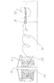
線材供給部(サプライスタンド)51の上下腕51A、51Bの各先端から線材コイル53を単線状の線材54に繰り出す線材供給部51と、その下手側の伸線機52からなる線材繰り出しラインの従来の模式図を図6に示す。また、図7は、線材供給部51側から線材54を繰り出している斜視図である。
線材コイル53は、固定された上腕51Aに自重をかけて、線材供給部51の上下腕6A、6Bに懸垂されている。線材供給部51の下腕51Bの先端は、下腕51Bの根元を基点として上下可動であって、線材54の繰り出しにともなって上下に動く。そして、ダイスボックス55中のダイスを通して線材54を引き抜く伸線機52の力によって、線材供給部51の線材54は引っ張られて順次繰り出される。図6では図面に向かって右に、図7では右やや斜め上に繰り出される。
A conventional wire rod feed line comprising a wire rod feeder 51 that feeds a
The
そのような場合に、巻き取られた線材コイルに発生している捩れを相殺する捩れを与えるようにして線材コイルを繰り出して、捩れを除去する方法が提供されている。線材コイルを横置きにした状態で懸架する線材供給部、単線状の線材に繰り出すピンチロール装置等が備えられている。(例えば、特許文献1参照。)。
また、線材繰り出し不良検出装置であって、線材供給部と伸線機との間の線材引出しラインにおいて、伸線機の最初のダイスボックスの入口に近いところのダイスの孔の中心線に同軸された導電性金属製の輪具が不良検出用電源に接続されているものもある(例えば、特許文献2参照。)。
Also, the wire drawing failure detection device is coaxial with the center line of the die hole near the entrance of the first die box of the wire drawing machine in the wire drawing line between the wire supply unit and the wire drawing machine. Some conductive metal rings are connected to a failure detection power source (see, for example, Patent Document 2).
しかしながら、従来の図6(図7)や、特許文献1記載のものは、線材供給部の上下腕に懸架された線材コイルから繰り出された線材同士が衝突したり、多数の線材コイルが一度に飛び出す等といった欠点があった。繰り出された線材同士が衝突したり、あるいは線材が線材供給部に衝突したりする衝突音は、職場の好ましくない騒音となる。
また、線材コイルを巻きほどくような繰り出しに抗する抵抗、すなわち線材コイルの自重と上下腕、あるいは線材コイルと上腕上部に設けられた線押さえ等との摩擦力、さらには線材コイルが単線状の線材に形状が変貌することに対する線材自体の抵抗力等の、抵抗の変動・局所化などのため、繰り出された線材に疵が発生したり、線材にKink(もつれ)箇所が生じることもある。
However, in the conventional one shown in FIG. 6 (FIG. 7) and
In addition, the resistance against unwinding that unwinds the wire coil, that is, the frictional force between the weight of the wire coil and the upper and lower arms, or the wire retainer provided on the upper portion of the wire coil and the upper arm, and the wire coil is a single wire Due to the fluctuation and localization of resistance, such as the resistance of the wire itself against the transformation of the shape of the wire, wrinkles may occur in the drawn-out wire, or a Kink (entangled) location may occur in the wire.
そこで、本発明は、上記問題点に鑑み、衝突音のような不愉快な騒音の発生がなく、疵やKink(もつれ)個所がない線材をスムーズに繰り出す線材繰り出し装置を提供するものである。 Therefore, in view of the above problems, the present invention provides a wire feeding device that smoothly feeds a wire that does not generate unpleasant noise such as a collision sound and has no wrinkles or kinks.
この技術的課題を解決するための本発明の技術的手段は、線材コイルを単線状の線材で線材供給部の上下腕の各先端から繰り出す線材供給部とその下手側の伸線機からなる線材繰り出しラインにおいて、線材を挿通して線材コイルを巻きほどくように繰り出すためであって、前記線材供給部の上腕の先端部上方を通り、かつ該上腕の先端部下方を中心とする円弧軌跡面で自在に揺動するように支持されたガイドローラを伸線機の力で繰り出された線材によって回転するリング状縦型回転体に配設している点にある。
線材コイルを巻きほどくように単線状の線材として繰り出すために、線材コイルと上下腕との間で疵の発生するような余分な摩擦力が発生せず、また線材コイルが単線状の線材に形状が変貌することに対する線材自体の抵抗力等が少なく線材に疵やKink(もつれ)個所が発生しない。
The technical means of the present invention for solving this technical problem is a wire rod comprising a wire rod feeding unit that feeds a wire coil from each tip of upper and lower arms of a wire rod feeding unit with a single wire rod, and a wire drawing machine on the lower side thereof. In the payout line, the wire rod is inserted so as to unwind the wire rod coil, and passes through the upper end portion of the upper arm of the wire rod supply portion and has an arc trajectory surface centering on the lower end portion of the upper arm. A guide roller supported so as to freely swing is disposed on a ring-shaped vertical rotating body that is rotated by a wire fed by a wire drawing machine.
Since the wire coil is unwound as a single wire, the extra frictional force that generates wrinkles between the wire coil and the upper and lower arms does not occur, and the wire coil is shaped into a single wire. There is little resistance of the wire itself to the transformation of the wire, and no wrinkles or kinks are generated in the wire.
また、本発明の技術的手段は、前記線材繰り出しラインにおける前記線材供給部に近い個所に、空洞内を線材が通過するリング状縦型架台と、リング状縦型架台の反伸線機側であって、同じく空洞内を線材が通過しかつ線材繰り出しライン方向に直角に回転自在なリング状縦型回転体とを線材繰り出しライン方向に直角に各々立設し、前記リング状縦型回転体の反伸線機側であって前記線材繰り出しライン方向に沿って設けられた支持腕の反伸線機側先端に前記ガイドローラが前記円弧軌跡面で自在に揺動するように支持されている点にある。 Further, the technical means of the present invention includes a ring-shaped vertical frame through which the wire passes through the cavity at a location near the wire rod supply part in the wire feeding line, and an anti-drawer side of the ring-shaped vertical frame. And a ring-shaped vertical rotating body that passes through the cavity and is rotatable at right angles to the wire feed-out line direction, respectively, and is erected at right angles to the wire feed-out line direction. The guide roller is supported at the tip of the anti-drawing machine side of the support arm provided along the wire feed line direction on the side of the anti-drawing machine so as to freely swing on the arc locus surface. It is in.
また、本発明の技術的手段は、リング状縦型回転体の支持腕で支持されたガイドローラに相対峙して該回転体の回転中心を挟んでカウンターウエイトを該回転体に設けている点にある。
また、本発明の技術的手段は、ガイドローラを支持する支持腕とカウンターウエイトとを補強体で連結している点にある。
また、前記リング状縦型回転体の回転部の外周側面に押接されたローラに逆回転防止用ワンウエイクラッチが設けられていることを特徴とする。
Further, the technical means of the present invention is that a counterweight is provided on the rotating body so as to face the guide roller supported by the support arm of the ring-shaped vertical rotating body and sandwich the rotation center of the rotating body. It is in.
The technical means of the present invention resides in that the support arm that supports the guide roller and the counterweight are connected by a reinforcing body.
Further, a reverse rotation preventing one-way clutch is provided on a roller pressed against the outer peripheral side surface of the rotating portion of the ring-shaped vertical rotating body.
本発明の線材繰り出し装置によれば、線材を引っ張る力によりリング状回転体の回転部が回転して適量の線材を繰り出していくため、線材が多数飛び出して絡まる等のトラブルが発生しない。
ガイドローラが線材をほどくようにして繰り出していくために勢いよく飛び出した線材が線材供給部や線材同士で衝突して大きい騒音を出していたが、そのような大きい騒音がなくなった。
従来の線材供給部による線材の繰り出しでは、線材供給部の下腕等で線材が繰り出しすぎないように無理矢理線材を押さえ込んでいたため、線材が繰り出される際には、それらの抵抗と強く擦れあう事となり、線材の疵の原因となっていた。しかし、本発明の線材繰り出し装置では、ガイドローラが回転しながら線材コイルをほどくようにして繰り出していくため、線材等が強く擦れあう部分がなく、線材に疵がつかず、線材にKink(もつれ)箇所が生じることもない。
According to the wire rod feeding device of the present invention, the rotating portion of the ring-shaped rotator rotates by the force pulling the wire rod to feed an appropriate amount of wire rod, so that troubles such as a large number of wire rods popping out and tangling do not occur.
Since the guide roller unwinds the wire rod and the wire rod popped out vigorously collided with the wire rod supply unit and the wire rods to generate a large noise, such a large noise disappeared.
In the conventional wire feeding by the wire feeding part, the wire rod is pushed down so that the wire rod is not drawn too much by the lower arm etc. of the wire feeding part, so when the wire is fed out, it will rub against the resistance strongly. It was a cause of wrinkles of the wire. However, in the wire feeding device of the present invention, the guide roller rotates and unwinds the wire coil so that there is no portion where the wire or the like rubs strongly, the wire does not wrinkle, and the wire has Kink (entanglement). ) There is no point.
さらに、本発明の線材繰り出し装置はモーター駆動を必要としない為特段の電気配線が不要であるだけでなく、伸線機等の線材加工装置との同調等の電気制御も必要としない。
なお、リング状縦型架台の底面に車輪等の移動体を備えたため、ガイドローラに線材が絡まる等不測のトラブルが発生し、かつ無人運転の場合であっても、リング状縦型架台が移動して、線材繰り出しラインに設けられたリミットスイッチを叩き、線材の繰り出しを停止できる。
また、既存の線材供給部等の線材繰り出しラインをそのまま使用可能であって、線材供給部や伸線機等の生産機械の特段の配置変更等に要する経費は必要としない。
Furthermore, since the wire feeding device of the present invention does not require a motor drive, special electrical wiring is not required, and electrical control such as synchronization with a wire processing apparatus such as a wire drawing machine is not required.
In addition, since the moving body such as a wheel is provided on the bottom of the ring-shaped vertical frame, unexpected troubles such as a wire tangled around the guide roller occur, and the ring-shaped vertical frame moves even in the case of unmanned operation. Then, a limit switch provided in the wire feeding line can be hit to stop the feeding of the wire.
In addition, the wire supply line such as the existing wire supply unit can be used as it is, and there is no need for the special arrangement change of the production machine such as the wire supply unit and the wire drawing machine.
以下、本発明の実施の形態を図面に基づいて説明する。
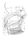
図1は、本発明に係る線材繰り出し装置1の斜視図であって、同図において、本発明の線材繰り出し装置1は、リング状縦型架台2と、リング状縦型架台2に設けられたリング状縦型回転体3とから主構成されている。
上記線材繰り出し装置1は、線材供給部6とその下手側の伸線機(同じく図示しない伸線機前のダイスボックス等も含む。)からなる線材繰り出しラインの間に設けられている。線材繰り出しラインの状況は、前記[背景技術]で説明した第6図で示しているのと同様である。また、図1の線材供給部6の上下腕6A、6Bの先端の形状が、図6(図7)とは少し相違しているが、図1に示す上下腕6A、6Bの先端の形状が図6(図7)であっても有効である。
Hereinafter, embodiments of the present invention will be described with reference to the drawings.
FIG. 1 is a perspective view of a
The wire
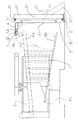
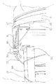
リング状縦型架台2は、図2に側面図、図3に正面図(ただし、線材供給部6側、すなわち反伸線機側からの模式図)に示されているように、中央は大きく空洞2Aを成す所謂ドーナツ形状のリング状部2B、並びにリング状部2Bを支える架台部2Cからなる。なお、図2の線材コイル21、線材22は破線で示している。また、図3では線材22は示していない。
このリング状縦型架台2は、線材供給部6とその下手側の伸線機とを結ぶ線材繰り出しラインに直角に、そして垂直方向に立設されている。空洞2A内を繰り出された線材22が伸線機側に向かって矢印で示すように通過してゆく。さらに、このリング状部2Bの反伸線機側、すなわち線材供給部6側にベアリング2Dをリング状部2Bに沿って設けている。
As shown in the side view of FIG. 2 and the front view of FIG. 3 (however, the center is large as shown in the schematic view from the wire supply unit 6 side, that is, the anti-drawing machine side). It consists of a so-called donut-shaped ring-
The ring-shaped
リング状縦型回転体3は、回転部3B、ガイドローラ支持腕4並びにガイドローラ5から構成されている。リング状縦型回転体3も、リング状縦型架台2と同様に線材繰り出しラインに直角に、そして垂直方向に立設されている。また、リング状縦型回転体3の空洞3A内を繰り出された線材22が伸線機側に向かって通過してゆく。
回転部3Bは、図2に側面図、図3に正面図が示されているように、中央は大きく空洞3Aを成す所謂ドーナツ形状をなし、前記リング状縦型架台2のベアリング2Dに係合しており、そしてリング状縦型架台2のリング状部2Bに沿って垂直で縦方向に回転・旋回可能なものである。なお、回転部3Bの外周側3Eの輪郭も回転部Bと同じ回転中心を持つ滑らかな円である。
The ring-shaped vertical rotating body 3 includes a rotating
As shown in the side view of FIG. 2 and the front view of FIG. 3, the rotating
回転部3Bがリング状部2Bに設けられたベアリング部2Dに係合しているために、回転部3Bの回転・旋回の抵抗は少なく、スムーズに回転・旋回する。
また、ガイドローラ5を支持している支持腕4は、リング状縦型回転体3の反伸線機側であって前記線材繰り出しライン方向に沿って設けられている。
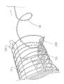
ガイドローラ5は、拡大斜視図を図4に示すように、前記支持腕4の反伸線機側の先端4Aに支持されている。このガイドローラ5は、平ローラ5Aと縦ローラ5Bが接近して設けられた井桁状のものである。
Since the rotating
The
As shown in FIG. 4 in an enlarged perspective view, the
図1〜4に示すように、平ローラ5Aには深溝5Cが設けられ、繰り出される線材22の主に上下動を規制している。縦ローラ5Bは溝のないものであって、同じく主に水平動を規制している。
このガイドローラ5に挿通された線材22は、線材コイルを巻きほどくように繰り出される。もちろん、このガイドローラ5から線材22が脱落することがないようにガイドローラ4の平ローラ5A並びに縦ローラ5Bは組み合わされている。
ガイドローラ5は、線材22を挿通するもので、線材供給部6の上腕6Aの先端部6Cから距離L(図5)を持って先端部6Cの上方を通るので、先端部6Cに接触することがない。なお、下記に説明するように、先端部6Cの長さは、線材供給部6の上腕6Aの最先端から、ガイドローラ5が被さっている長さに相当する。また、先端部6Cの位置は固定されている。
As shown in FIGS. 1 to 4, the
The
The
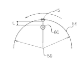
ガイドローラ5は、上腕6Aの先端部6Cの下方に中心5Dを持つ円弧軌跡面5Eで自在に揺動するように支持腕4(リング状縦型回転体3における回転部3Bに設けられている。)の先端4Aに支持されている。これらの中心5D、円弧軌跡面5E等の関係を模式的に図5に示す。図5においては、ガイドローラ5並びに(線材供給部6の上腕6Aの)先端部6C両者を結ぶ垂直断面を模式的に示している。また、ガイドローラ5の揺動方向(下記逆回転防止用ワンウエイクラッチ7を設けている場合は、反時計まわり方向)は、ガイドローラ5の上部に示している。
The
中心5D及び円弧軌跡面5Eは、ガイドローラ5が支持されるリング状縦型回転体3における回転部3Bの回転と、線材供給部6の上腕6Aの先端部6Cとの位置により決定される。
ガイドローラ5の支持には、支持角度・位置をネジ止め等を採用して自由に変更できるようにする。しかし、ガイドローラ5は線材供給部6の上腕6Aの先端部6Cの上方を通るものであって、ガイドローラ5は上腕6Aの先端部6Cに上方から被さるようになっている。
The
For the support of the
ガイドローラ5は線材供給部6上腕6Aの先端部6Cの上方を通るので、線材供給部6の上腕6Aの最先端から線材22が脱落することがない。線材22の前記脱落が発生すると、線材同士や、線材と線材供給装置との衝突音のような騒音や、線材に疵やKink(もつれ)個所が発生し、時に線材が断線することもあり、線材コイルを巻きほどくように滑らかに繰り出すことは不可能となる。
線材供給部6とその下手側の伸線機との間の線材繰り出しラインに、本願発明の線材繰り出し装置1を設けることにより、前記[背景技術]でも述べたように、下手側の伸線機の線材22を引き抜く力で線材22が(下手側に)引っ張られることにより、リング状縦型回転体3の回転部3Bが回転する。
Since the
By providing the
この回転部3Bは、線材22が前記のように引っ張られることによってのみ回転し、モーター等の動力源によって回転するものではない。
回転抵抗の極めて少ない回転部3Bは、線材22が引っ張られて線材22に張力が発生したときのみ回転し、線材22がある程度繰り出されて張力が弱くなると回転は止まる。すなわち、回転部3Bの回転は、線材22の繰り出しに応じて自動的に調整されるようなセルフコントロールとなる。
逆に、本発明の線材繰り出し装置1に入線している線材22も回転部3Bが回転しているときのみ繰り出されるため、必要以上に線材22が出ることなく、スムーズな線材22の繰り出しとなる。なお、回転部3Bが回転できるためには、直径9mm以上の太径線材が有効であるが、それに限定するものでもない。
The rotating
The rotating
On the contrary, since the
また、線材コイル21の外周に沿って線材22をほどくようにガイドローラ4が回転して線材22を繰り出していくため、線材22同士が衝突して不愉快な騒音を出すことがない。線材22同士や、線材22と線材供給装置6等との衝突音のような騒音の発生がない。具体的には、操業時の騒音は90dbを記録し、従来の騒音レベルを大幅に低下させることができた。なお、この90dbは、周囲の機械の音も拾った結果であって、周囲に音(騒音)がない場合にはもっと低い値となると考えられる。
なお、リング状縦型回転体3の回転部3Bの回転のバランスを向上するために、ガイドローラ5に相対峙して回転部3Bの回転中心を挟んでカウンターウエイト3Cを回転部3Bに設ける。このカウンターウエイト3Cは、どのような形態でもかまわないが、図3のようにそのウエイトを調整できるようなブロック形式でも良い。
Moreover, since the
In order to improve the balance of rotation of the
また、線材繰り出し装置1、主にリング状縦型回転体3の回転部3Bの補強のために、ガイドローラ5とカウンターウエイト3Cの間を補強体3Dである鉄パイプで連結している。この補強体3Dは、リング状縦型回転体3における回転部3Bの空洞3Aを直径方向に横切るものである。
その補強はリング状縦型回転体3、主に回転部3Bのリング形態を保つためであり、しかも回転部3Bのスムーズな回転に役立つ。しかし、この補強体3Dは、空洞3Aを通過する線材22の通過の邪魔にはならない。線材22が挿通するガイドローラ5を支持する支持腕4の反ガイドローラ5側に補強体3Dが設けられているためで、逆にいえば、ガイドローラ5が線材22と補強体との接触がないような働きをする。
Further, in order to reinforce the
The reinforcement is to maintain the ring shape of the ring-shaped vertical rotating body 3, mainly the
また、リング状縦型回転体3の回転部3Bの外周側3Eに沿うようなローラ8に逆回転防止用ワンウエイクラッチ7が設けられている。ワンウエイクラッチ7が設けられたローラ8は、リング状縦型架台2の架台部2Cからシリンダー9等を介して前記外周側3Eに押接して取付けられている。なお、ローラ8とは別に同様に外周側3Eに押接して滑り止めブレーキ10(図1、図3)が設けられているが、厳しく滑り止めを働かせる必要はなく、スムーズに回転部3Bが回転すれば良い。
このワンウエイクラッチ7は、リング状縦型回転体3の回転部3Bが勢いよく回転した場合、その後、逆回転してしまうことがあるためで、逆回転すると一度ほどけた線材22が線材繰り出し装置1の支持腕4に絡まる等の線材繰り出しにトラブルを生じるので、逆回転を防止するために取り付けている。ローラ8が一方向の回転であることを矢印で示している。
Further, a reverse rotation preventing one-way clutch 7 is provided on the
This one-way clutch 7 may reversely rotate thereafter when the
また、補助的な装置としてリング状縦型架台2(並びにリング状縦型回転体3)が、線材供給部6とその下手側の伸線機との間の線材繰り出しライン方向に沿って移動(スライド)できるようリング状縦型架台2の架台部2Cの底面に移動体(図示せず)を設ける。この移動体は車輪である。
これは、ガイドローラ4に線材22が絡まる等のトラブルが発生し、絡まった線材22を通じてリング状縦型架台2が伸線機(図示せず)側に引っ張られた際、リング状縦型架台2(並びにリング状縦型回転体3)全体が移動(スライド)することにより、線材繰り出しラインに沿って設けられた伸線機等を停止するリミットスイッチを叩いて、伸線機等を停止する。停止することにより、引っ張られたリング状縦型架台2等が伸線機の前に隣接して設けられたダイスボックス等に衝突するなどのトラブルを防止できる。
Further, as an auxiliary device, the ring-shaped vertical mount 2 (and the ring-shaped vertical rotating body 3) moves along the wire feed line direction between the wire supply unit 6 and the lower wire drawing machine ( A movable body (not shown) is provided on the bottom surface of the gantry portion 2C of the ring-shaped
This is because troubles such as the
なお、本発明の実施形態は、上記に限定するものではなく、例えば、リング状縦型架台2のベアリング2Dは、複数個の車輪でも構わない。さらには、リング状縦型架台2やリング状縦型回転体3の空洞2A、3Aの内面あるいは補強体3D等と、通過する線材22とが触れて線材22が擦られることのないように、それらの内面に補助ローラ(図示せず)等を別途設けて、その補助ローラに線材を挿通して線材の繰り出される方向を指定することもできる。もっとも、線材コイル21のコイル径が縮小されながら繰り出されるため、線材が擦られる前記のような状況の発生はほとんど起こりえない。
The embodiment of the present invention is not limited to the above. For example, the bearing 2D of the ring-shaped
本発明の線材繰り出し装置は、硬い鋼の線材の伸線以外に、コイル状の撚り線等の長物を順次繰り出して保管形態を変えたり、順次繰り出して定尺に切り揃えたりするのにも利用可能である。 The wire feeding device of the present invention can be used to change the storage form by sequentially drawing long materials such as coiled stranded wires in addition to the drawing of hard steel wire, or to sequentially draw and align them to a standard length. Is possible.
1 線材繰り出し装置
2 リング状縦型架台
2B リング状部
2D ベアリング
3 リング状縦型回転体
3B 回転部
3C カウンターウエイト
3D 補強体
4 支持腕
5 ガイドローラ
6 線材供給部
6A 上腕
6C 先端部
7 ワンウエイクラッチ
21 線材コイル
22 線材
DESCRIPTION OF
Claims (5)
Priority Applications (1)
| Application Number | Priority Date | Filing Date | Title |
|---|---|---|---|
| JP2004119402A JP2005297035A (en) | 2004-04-14 | 2004-04-14 | Wire feeding device |
Applications Claiming Priority (1)
| Application Number | Priority Date | Filing Date | Title |
|---|---|---|---|
| JP2004119402A JP2005297035A (en) | 2004-04-14 | 2004-04-14 | Wire feeding device |
Publications (1)
| Publication Number | Publication Date |
|---|---|
| JP2005297035A true JP2005297035A (en) | 2005-10-27 |
Family
ID=35329212
Family Applications (1)
| Application Number | Title | Priority Date | Filing Date |
|---|---|---|---|
| JP2004119402A Pending JP2005297035A (en) | 2004-04-14 | 2004-04-14 | Wire feeding device |
Country Status (1)
| Country | Link |
|---|---|
| JP (1) | JP2005297035A (en) |
Cited By (2)
| Publication number | Priority date | Publication date | Assignee | Title |
|---|---|---|---|---|
| CN102423861A (en) * | 2011-10-09 | 2012-04-25 | 宁波新州焊接设备有限公司 | Discharge mechanism of steel bar truss forming machine |
| CN110665993A (en) * | 2019-10-16 | 2020-01-10 | 嘉兴涵祺汽配科技有限公司 | Wire unwinding device for bolt multi-station forming machine |
-
2004
- 2004-04-14 JP JP2004119402A patent/JP2005297035A/en active Pending
Cited By (2)
| Publication number | Priority date | Publication date | Assignee | Title |
|---|---|---|---|---|
| CN102423861A (en) * | 2011-10-09 | 2012-04-25 | 宁波新州焊接设备有限公司 | Discharge mechanism of steel bar truss forming machine |
| CN110665993A (en) * | 2019-10-16 | 2020-01-10 | 嘉兴涵祺汽配科技有限公司 | Wire unwinding device for bolt multi-station forming machine |
Similar Documents
| Publication | Publication Date | Title |
|---|---|---|
| US20060266794A1 (en) | Method and apparatus for packaging wire in a wire container | |
| JP2010195522A (en) | Method for storing welding wire | |
| JP7682809B2 (en) | Straightening device for straightening a line, method for braking at least one rotatable roller in a straightening device, cable management machine having a straightening device, and upgrade kit for a cable management machine | |
| KR102135724B1 (en) | Winding apparatus | |
| CN107208370A (en) | Wire twisting machine | |
| US2390157A (en) | Wire pay-off reel | |
| WO2020230365A1 (en) | Jumper wire forming device and jumper wire forming method | |
| JP2020528391A (en) | Methods and systems in which twisted braided metal cables or flat wires are fed from the corresponding supports without changing their structure or shape. | |
| US6000656A (en) | Space saving wire drawing machine with floor mounted wire coil | |
| JP5876158B2 (en) | Device comprising a rotating arm for unwinding a strand of material | |
| JP2000190024A (en) | Top-up type feeding method for wire coil and wire coil entanglement preventing device used therefor | |
| CN110817564A (en) | Strand pay-off support | |
| CN215047641U (en) | Pay-off reel | |
| JP2020125188A (en) | Device for feeding long objects | |
| CN212075923U (en) | A smooth and orderly unwinding device | |
| CN210193011U (en) | A kind of spool speed protection control device | |
| CN211141086U (en) | Strand pay-off support | |
| JPH05253618A (en) | Uncoiler for wire rod coil | |
| JP2528992B2 (en) | Cable basket and crane | |
| JP2006316390A (en) | Weft supplying device of loom | |
| CN217831275U (en) | Copper clad aluminum wire drawing device convenient to quick wire drawing | |
| CN219990751U (en) | Magnetic tension paying-off device for steel cord production | |
| JP3534709B2 (en) | Method and apparatus for winding a suspension wire | |
| JP7352868B2 (en) | Wire rod feeding device and mounting table | |
| JPH0663547U (en) | Wire feeding device |
Legal Events
| Date | Code | Title | Description |
|---|---|---|---|
| A131 | Notification of reasons for refusal |
Free format text: JAPANESE INTERMEDIATE CODE: A131 Effective date: 20061205 |
|
| A02 | Decision of refusal |
Effective date: 20070403 Free format text: JAPANESE INTERMEDIATE CODE: A02 |