JP2005297436A - Liquid storage container and manufacturing method thereof - Google Patents
Liquid storage container and manufacturing method thereof Download PDFInfo
- Publication number
- JP2005297436A JP2005297436A JP2004119024A JP2004119024A JP2005297436A JP 2005297436 A JP2005297436 A JP 2005297436A JP 2004119024 A JP2004119024 A JP 2004119024A JP 2004119024 A JP2004119024 A JP 2004119024A JP 2005297436 A JP2005297436 A JP 2005297436A
- Authority
- JP
- Japan
- Prior art keywords
- liquid
- supply member
- liquid supply
- opening
- storage container
- Prior art date
- Legal status (The legal status is an assumption and is not a legal conclusion. Google has not performed a legal analysis and makes no representation as to the accuracy of the status listed.)
- Pending
Links
Images

Landscapes
- Ink Jet (AREA)
Abstract
Description
本発明は、各種記録分野に利用されるインクジェットヘッドカートリッジに関するものであり、更に詳しくはピットインインク供給方式に好適なインクジェットカートリッジとその液体貯蔵部、並びに液体貯蔵部の製造方法に関するものである。 The present invention relates to an ink-jet head cartridge used in various recording fields, and more particularly to an ink-jet cartridge suitable for a pit-in ink supply system, a liquid storage part thereof, and a method for manufacturing the liquid storage part.
インクジェット記録装置の一つの形態として、少なくとも液体吐出ヘッドと、該液体吐出ヘッドへインクを供給するための液体貯蔵容器であるサブタンクと、該サブタンクにインクを補充する容器であるメインタンクを備えたピットイン方式の装置が提供されている。これは、紙、葉書などの記録媒体に対し、液体吐出ヘッドが記録媒体の搬送方向と交差する方向に移動しつつ液体を吐出して記録を行い、定期的にサブタンクとメインタンクを接続させる方式である。 As one form of an ink jet recording apparatus, a pit-in includes at least a liquid discharge head, a sub tank that is a liquid storage container for supplying ink to the liquid discharge head, and a main tank that is a container for replenishing the sub tank with ink. A device of the type is provided. This is a system in which a liquid discharge head discharges liquid on a recording medium such as paper or postcard while moving in a direction crossing the recording medium conveyance direction, and the sub tank and main tank are connected periodically. It is.
液体吐出ヘッドは、サブタンクと一体的に構成され、この液体吐出ヘッドとサブタンクからなるインクジェットヘッドカートリッジ(以下、ヘッドカートリッジと略す)が、記録媒体の記録面に対向して走査されるキャリッジに装着される。サブタンクの一部にはメインタンクと接続する液体供給部材が設けられている。また、メインタンクはインクジェット記録装置本体に対し脱着可能に装置内に収納されている。 The liquid discharge head is configured integrally with a sub tank, and an ink jet head cartridge (hereinafter abbreviated as a head cartridge) composed of the liquid discharge head and the sub tank is mounted on a carriage that is scanned to face a recording surface of a recording medium. The A liquid supply member connected to the main tank is provided in a part of the sub tank. The main tank is housed in the apparatus so as to be detachable from the ink jet recording apparatus main body.
サブタンクは、キャリッジの移動とともに所定の位置でメインタンクと液体供給部材によって接続され、インクが補充される。 The sub tank is connected by a main tank and a liquid supply member at a predetermined position as the carriage moves, and is replenished with ink.
このピットイン方式にてインクを補充する場合に所定量のインクを過不足なくサブタンクに補充する構成が必要となる。 In the case of replenishing ink by this pit-in method, a configuration for replenishing a sub tank with a predetermined amount of ink without excess or deficiency is required.
したがって、確実にメインタンクに、サブタンクの一部に設けられた液体供給部材を接続することが必要となる。さらに、サブタンクへのインク充填はインクの消費にともない複数回行われるため、メインタンクにサブタンクの液体供給部材を接続する際の信頼性、耐久性が重要となる。 Therefore, it is necessary to securely connect the liquid supply member provided in a part of the sub tank to the main tank. Further, since the ink filling into the sub tank is performed a plurality of times as the ink is consumed, reliability and durability when connecting the liquid supply member of the sub tank to the main tank are important.
ここで、インク補充においては、サブタンクの大気に開放する部分(以下、大気連通部と呼ぶ。)に逆止弁を設け、サブタンク内の気体を大気に開放しつつサブタンク内のインク量が満タン状態を超えた場合のインク溢れを防ぐような弁の開閉制御によってインクを充填する構成がある。 Here, in ink replenishment, a check valve is provided in a portion of the sub tank that is open to the atmosphere (hereinafter referred to as an atmospheric communication portion), and the amount of ink in the sub tank is fully filled while releasing the gas in the sub tank to the atmosphere. There is a configuration in which ink is filled by opening / closing control of a valve to prevent ink overflow when the state is exceeded.
この逆止弁として、大気連通部に、気体を透過させ、かつ、インクなどの液体を通過させない多孔質からなる撥水性の繊維状の膜を貼り付けることで、サブタンクへのインク補充の際に、内部の空気を排除しつつインクのみを充填し、上記の膜のメニスカス保持力によって、満タン補充を行うという構成が特許文献1に提案されている。
ピットイン方式による上記のインク補充システムは多孔質からなる撥水性の繊維状の膜を貼り付けによってなされているので、コストがかからない、小型化に優れているなどの利点がある。しかし、メインタンクにサブタンクの液体供給部材を接続する動作がサブタンク内のインクの消費にともない複数回行われるため、メインタンクとサブタンクの液体供給部材とを接続する度に、液体供給部材の取り付け強度が低下していく場合がある。 The ink replenishing system using the pit-in method is formed by attaching a porous water-repellent fibrous film, and therefore has advantages such as low cost and excellent miniaturization. However, since the operation of connecting the liquid supply member of the sub tank to the main tank is performed a plurality of times as the ink in the sub tank is consumed, the attachment strength of the liquid supply member every time the main tank and the liquid supply member of the sub tank are connected. May go down.
特に、液体供給部材が接着剤などの介在部によってサブタンクに接合されていると、介在部の硬化時における接合強度のばらつき、ならびに長期間の複数回にわたる液体供給部材を接続する動作によって、インク接液での介在部の劣化を生じることがある。 In particular, when the liquid supply member is joined to the sub tank by an intervening part such as an adhesive, ink contact is caused by the dispersion of joining strength when the intervening part is cured and the operation of connecting the liquid supply member over a long period of time. The interposition part may be deteriorated by the liquid.
すなわち上記のような現象から、結果的に液体供給部材の接合部分に欠損を生じると、ピットイン供給時にサブタンクへのインク供給がなされなくなる。 That is, if a defect occurs in the joint portion of the liquid supply member as a result of the above phenomenon, ink is not supplied to the sub tank at the time of pit-in supply.
また、液体供給部材をより強固に固定する為に上記のような接着剤の使用に替わり、熱溶着を使った方法がとられるが、装置の超小型化を達成する為に、メインタンクとサブタンクとのジョイント時のクリアランスは少ない。従って、熱溶着時に発生する溶着部の盛り上がりが、メインタンクとのジョイント時に干渉を起こし、正常な接続動作ができなくなりインク供給がなされなくなるという不具合も起こりうる。 In order to more firmly fix the liquid supply member, instead of using the adhesive as described above, a method using thermal welding is used, but in order to achieve ultra-miniaturization of the apparatus, the main tank and the sub tank There is little clearance at the time of joint. Therefore, the swell of the welded portion that occurs during heat welding causes interference at the time of jointing with the main tank, so that a normal connection operation cannot be performed and ink supply cannot be performed.
この場合、サブタンクのインクが、液体供給部材の接合部から漏洩し、ヘッドカートリッジ外部に漏洩し、場合によってはインク供給を行うシステム全体にインクが漏洩し電気系統のショートなどの致命的な動作不良の原因となる。 In this case, the ink in the sub tank leaks from the junction of the liquid supply member, leaks to the outside of the head cartridge, and in some cases, the ink leaks to the entire system that supplies ink, resulting in a fatal malfunction such as a short circuit in the electrical system. Cause.
本発明の目的は、上記インク供給時の不良に鑑みてなされたものであり、上記のメインタンクと液体貯蔵容器(サブタンク)の接続動作が頻繁に行われる例えばピットイン方式において、インク供給性能を安定させる、液体貯蔵容器及びその製造方法を提供することを目的とする。 An object of the present invention has been made in view of the above-described failure during ink supply, and the ink supply performance is stabilized in, for example, the pit-in method in which the connection operation between the main tank and the liquid storage container (sub tank) is frequently performed. An object of the present invention is to provide a liquid storage container and a method for producing the same.
本発明の更なる目的は、上記のメインタンクとサブタンクの接続動作の不良、ならびにインク漏洩の課題に着目し、接続性能を安定し、インク漏れがなく信頼性の高い、インクジェットヘッドカートリッジを提案することを目的とする。 A further object of the present invention is to propose an ink jet head cartridge that has stable connection performance and is highly reliable without ink leakage, focusing on the above-mentioned poor connection operation between the main tank and the sub tank and the problem of ink leakage. For the purpose.
上記目的を達成するために本発明は、液体を貯蔵する貯蔵部と、前記貯蔵部の一部に設けられた、前記貯蔵部の内部と外部を連通させる開口部と、前記開口部に装着され、外部容器内の液体を前記貯蔵部内に供給するための液体供給部材とを備え、前記液体供給部材の、前記開口部の内側面に対応する面が凹凸面である液体貯蔵容器を提供する。 In order to achieve the above object, the present invention is equipped with a storage section for storing a liquid, an opening provided in a part of the storage section for communicating the inside and the outside of the storage section, and the opening section. A liquid supply member for supplying the liquid in the external container into the storage unit, and a surface of the liquid supply member corresponding to the inner surface of the opening is an uneven surface.
このような発明では、液体供給部材を貯蔵部の開口部に圧入した後、液体供給部材における貯蔵部の外側に出た部分を加熱すると、前記開口部に熱の温度勾配が生じ、前記貯蔵部の外側から内側へと温度が低くなる。このため、開口部の貯蔵部外側では貯蔵部内側より樹脂の溶融状態が多くなり、液体供給部材の凹凸面部分への樹脂の流れ込み性が上がる。つまり、開口部の貯蔵部外側の方が液体供給部材に対する樹脂の密着性が高くなる。この結果、外部容器と液体供給部材の接続を頻繁に繰り返し行っても、液体供給部材が抜け強度に対して強くなる。 In such an invention, after the liquid supply member is press-fitted into the opening of the storage unit, when the portion of the liquid supply member that has come out of the storage unit is heated, a temperature gradient of heat is generated in the opening, and the storage unit The temperature decreases from the outside to the inside. For this reason, the melted state of the resin is greater on the outer side of the storage part than on the inner side of the opening part, and the flowability of the resin to the uneven surface portion of the liquid supply member is improved. That is, the adhesiveness of the resin to the liquid supply member is higher on the outside of the storage part of the opening. As a result, even if the connection between the external container and the liquid supply member is frequently repeated, the liquid supply member becomes strong against the pulling strength.
また、本発明は、液体を貯蔵する貯蔵部と、前記貯蔵部の一部の面に設けられた凹部と、前記凹部の底面に設けられ、前記貯蔵部の内部を外部と連通させる開口部と、前記開口部に装着され、外部容器内の液体を前記貯蔵部内に供給するための液体供給部材とを有する液体貯蔵容器を提供する。この容器において、前記凹部内に樹脂が配設されていることが好ましい。 In addition, the present invention provides a storage unit for storing a liquid, a recess provided on a part of the surface of the storage unit, an opening provided on the bottom surface of the recess and communicating the inside of the storage unit with the outside. And a liquid supply container mounted on the opening and having a liquid supply member for supplying the liquid in the external container into the storage part. In this container, it is preferable that a resin is disposed in the recess.
この発明では、液体供給部材を貯蔵部の開口部に圧入した後、液体供給部材における貯蔵部の外側に出た部分を加熱すると、液体供給部材の自己発熱によって、液体貯蔵容器の開口部の、液体供給部材との接触部分の樹脂が溶け始める。このとき、液体貯蔵容器の開口部の液体供給部材との間に抱き込んでいるエアーは膨張して、溶融した樹脂を凹部へ押し出し、盛り上がりを形成する。 In this invention, after press-fitting the liquid supply member into the opening of the storage unit, when the portion of the liquid supply member that has come out of the storage unit is heated, the self-heating of the liquid supply member causes the opening of the liquid storage container to The resin at the contact portion with the liquid supply member begins to melt. At this time, the air embraced between the liquid supply member at the opening of the liquid storage container expands and pushes the molten resin into the recess to form a bulge.
上記の加熱動作が終了すると徐々に、溶融した開口部の樹脂が再び硬化し始める。この硬化とともに、開口部の樹脂は液体供給部材を密着固定する。特に盛り上がりはエアーを巻き込まない溶融した樹脂で形成されているため、液体に対して遮断する効果が生じる。 When the heating operation is finished, the molten resin in the opening gradually begins to harden again. Along with this curing, the resin in the opening tightly fixes the liquid supply member. In particular, the bulge is formed of a molten resin that does not entrain air, and thus has an effect of blocking the liquid.
その後、凹部内に、盛り上がりの上から封止剤としての樹脂を充填することで確実に液体を遮断して安定化を増すことができる。このとき、塗布する樹脂は凹部内に配設することにより、液体貯蔵容器の、液体供給部材の周辺部に突出物が無いので、液体貯蔵容器と外部容器が正常な接続動作でジョイントされる。
さらに液体供給部材の、貯蔵部の開口部の内側面に対応する面が凹凸面であれば、抜け強度に対しても更に強くなる。
Thereafter, filling the recess with resin as a sealant from the top of the bulge can reliably block the liquid and increase the stabilization. At this time, since the resin to be applied is disposed in the recess, there is no protrusion in the peripheral portion of the liquid supply member of the liquid storage container, so that the liquid storage container and the external container are jointed by a normal connection operation.
Furthermore, if the surface of the liquid supply member corresponding to the inner side surface of the opening of the storage unit is an uneven surface, the strength against dropping is further increased.
本発明によれば、液体を補充する外部容器に、液体貯蔵容器の一部に設けられた液体供給部材とを接続するごとに、液体供給部材の取り付け強度の低下を招くことがない。 According to the present invention, whenever the liquid supply member provided in a part of the liquid storage container is connected to the external container for replenishing the liquid, the attachment strength of the liquid supply member is not reduced.
特に、液体貯蔵容器に設けられた開口部と液体供給部材との接合が接着剤等などによる介在部が存在することがないため、介在部の硬化時における接合強度のバラツキ、ならびに長期間の複数回にわたる液体供給部材とを接続する動作時によって、インク接液での介在部の劣化を生じることがない。 In particular, since there is no intervening portion due to an adhesive or the like in the connection between the opening provided in the liquid storage container and the liquid supply member, there is a variation in bonding strength when the intervening portion is cured, and a plurality of long-term The intervening portion does not deteriorate due to the ink contact depending on the operation of connecting the liquid supply member to the liquid.
さらに、液体貯蔵容器に設けられた開口部と液体供給部材との接合部分に欠損を生じことなく、液体供給部材の接続、供給時に液体貯蔵部の気密性が保てる。すなわち、液体貯蔵容器の液体が、開口部と液体供給部材との接合部から漏洩することがないため、インクジェットヘッドカートリッジ外部にインクが漏洩し、場合によってはインク供給を行うシステム全体にインクが漏洩し電気系統のショートなどの致命的な動作不良を発生させる恐れがない。 Furthermore, the air tightness of the liquid storage unit can be maintained during connection and supply of the liquid supply member without causing a defect in the joint portion between the opening provided in the liquid storage container and the liquid supply member. That is, since the liquid in the liquid storage container does not leak from the joint between the opening and the liquid supply member, the ink leaks to the outside of the inkjet head cartridge, and in some cases, the ink leaks to the entire system that supplies the ink. There is no danger of a fatal malfunction such as a short circuit in the electrical system.
ピットイン供給方式に適用すれば、ジョイント性能を安定し、インク漏れの無く信頼性の高い、インクジェットヘッドカートリッジを提供することができる。 When applied to the pit-in supply method, it is possible to provide an inkjet head cartridge that has stable joint performance and high reliability without ink leakage.
以下、本発明の実施の形態について図面を参照して説明する。ここでは、液体を収容する液体貯蔵容器と、この容器から供給された液体を記録などのために吐出するインクジェット式の液体吐出ヘッドとを一体に備えたインクジェットヘッドカートリッジを例にとって説明するが、本発明の適用範囲はこれに限定されない。 Hereinafter, embodiments of the present invention will be described with reference to the drawings. Here, an ink jet head cartridge that integrally includes a liquid storage container that stores liquid and an ink jet liquid discharge head that discharges the liquid supplied from the container for recording or the like will be described as an example. The scope of the invention is not limited to this.
(実施形態1)
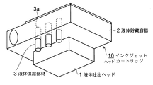
図1は本発明の実施形態1であるインクジェットヘッドカートリッジの概略斜視図である。
(Embodiment 1)
FIG. 1 is a schematic perspective view of an ink jet head cartridge according to
図に示すインクジェットヘッドカートリッジ10はインク等の液体を吐出するための吐出口を有するインクジェット式の液体吐出ヘッド1と、液体吐出ヘッド1へ液体を供給するための液体貯蔵容器2とを備える。液体貯蔵容器2の底面にはこの容器内へインクを補充するための液体供給部材3が接合されている。インクは不図示のメインタンク(外部容器)と液体供給部材3が接続されることによって供給される。
An inkjet head cartridge 10 shown in the figure includes an inkjet
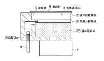
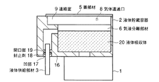
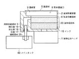
図2は液体貯蔵容器2を液体供給部材3の位置で切断した断面図である。
FIG. 2 is a cross-sectional view of the
液体貯蔵容器2の内部には、液体を吸収保持する液体吸収体20が充填されている。液体貯蔵容器2の上面は蓋部材5によって閉じている。
The
蓋部材5の液体貯蔵容器内側面には、気体を透過させ、かつ液体(インク)を透過させない多孔質からなる気液分離部材6が貼りつけられている。さらに、気液分離部材6の液体貯蔵容器内面側は撥水剤(不図示)が塗布され、蓋部材5と気液分離部材6の間の空間は、蓋部材5の気体連通口8(エアー吸引口)と連絡される連絡室9となっている。 A gas-liquid separation member 6 made of a porous material that allows gas to pass therethrough and does not allow liquid (ink) to pass through is attached to the inner surface of the liquid storage container of the lid member 5. Further, a water repellent (not shown) is applied to the inner surface of the liquid storage container of the gas-liquid separation member 6, and the space between the lid member 5 and the gas-liquid separation member 6 is a gas communication port 8 (air) of the lid member 5. The communication room 9 communicates with the suction port.
この気液分離部材6は、繊維状の樹脂や金属を積層させ焼結させた多繊維体であっても良く、この場合には、気体を透過する相当量が理論上の穴径に換算され、逆に理論上の穴径を狙って、繊維径や焼結後の密度が決定されて作製している。 The gas-liquid separation member 6 may be a multi-fiber body obtained by laminating and sintering a fibrous resin or metal. In this case, a considerable amount of gas permeating is converted into a theoretical hole diameter. On the contrary, the fiber diameter and the density after sintering are determined, aiming at the theoretical hole diameter.
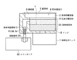
図3は液体貯蔵容器2にメインタンク60よりインク15を補充している状態での断面図である。図3中の符号aは、補充されたインク液面の位置を指している。
FIG. 3 is a cross-sectional view of the
インクの補充は液体供給部材3からなされ、補充する吸引力は気体連通口8に接続されるポンプなどの吸引負圧で行われる。
The ink is replenished from the
この吸引力によって、インクはメインタンク60から、互いに接続された接続部材25および液体供給部材3を介して、液体貯蔵容器2内へのインク供給がなされる。
With this suction force, ink is supplied from the main tank 60 into the
液体貯蔵容器2内へのインク補充がすすみ、気液界面を示す符号aの位置が液体吸収体20の収納部の上面、すなわち蓋部材5に貼り付けられた気液分離部材6の下面に到達すると、気液分離部材6の下面に塗布されている撥水の作用とメニスカス力によって、インク補充が止まるようにポンプの吸引圧が調整されている。その後、液体吐出ヘッド1で印刷のためのインク吐出が行われると徐々に液体貯蔵容器2内のインク15は消費される。
Ink replenishment into the
インク15の消費により気液界面aは徐々に低下するが、適当なタイミングによって、再びインクはメインタンク60から、接続部材25とジョイントした液体供給部材3を介して、液体貯蔵容器2内に充填される。
Although the gas-liquid interface a gradually decreases as the ink 15 is consumed, the ink is again filled into the
ここで構成されるインク部分に接する材料は、インクへの溶出を考慮して、液体貯蔵容器2および蓋部材5は、ポリサルホン、ポリエチレン、ポリプロピレン、HIPS、PES、PPE、PPSなどの耐食性と成形性のある樹脂で構成することが望ましい。本実施形態では、ポリサルホンを使用した。
The material in contact with the ink portion constituted here is in consideration of elution into the ink, and the
また、液体貯蔵容器2に接合された液体供給部材3は、インク充填が繰りかえされるごとに、メインタンク60の接続部材25とジョイントされるため、上記インクに対する接液性とジョイント時の接合強度の面から、ステンレス金属やセラミックス製が望ましい。また、樹脂であっても良い。本実施形態では、小型化の観点からステンレス(SUS303)を使用した。
Further, since the
また、本実施形態の液体供給部材3の外周面の、液体貯蔵容器2と接合する位置に凹凸状の凹凸面3aが設けられている。また、該液体供給部材3の外周面の、メインタンク60の接続部材25とジョイントされる部分は、繰り返しのジョイントにおける接続部材25の破損を防止するため滑らかな面となっている。
Moreover, the uneven |
次に、本実施形態における液体供給部材3と液体貯蔵容器2との接合方法について説明する。
Next, a method for joining the
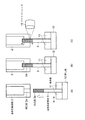
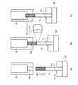
図4の(a)、(b)、(c)は本実施形態における液体供給部材と液体貯蔵容器との接合方法について説明した図である。図4では簡単のため液体貯蔵容器2の底面にある液体供給部材3を図の中央に置き、液体貯蔵容器2の底面部のみを拡大して示している。
4A, 4B, and 4C are diagrams illustrating a method of joining the liquid supply member and the liquid storage container in the present embodiment. In FIG. 4, for simplicity, the
図4(a)は液体貯蔵容器2に液体供給部材3を組み付ける前の状態である。この液体貯蔵容器2の一部に液体供給部材3を挿入するための開口部2aが設けられており、本実施形態の場合は、開口部2aは液体供給部材3よりも若干小さめに設計されていて、両者は圧入の嵌合となっている。
FIG. 4A shows a state before the
また、液体供給部材2は一対の保持具11の間に保持されている。本例では保持具11の片側は黒塗りの矢印方向に移動自在な構造であり、液体供給部材3の保持力の調整が可能である。さらに、液体供給部材3の軸上には液体供給部材3を液体貯蔵容器2の開口部2aへ挿入(ここでは圧入)するための押し具12がある。
The
図4(b)は液体貯蔵容器2に液体供給部材3を組み付けた状態である。この図に示すように、図4(a)の状態から、押し具12の押し付け力によって液体供給部材3が液体貯蔵容器2の開口部2aに挿入(圧入)される。液体供給部材3は凹凸部からなる凹凸面3aが開口部2aの内周面に対応するよう所定の位置まで圧入されている。
FIG. 4B shows a state in which the
次に図4(c)は液体貯蔵容器2に液体供給部材3を組み付け、液体供給部材3を間接加熱している状態である。この図に示すように、液体供給部材3に向けて、間接加熱を行うためのファイバーレンズ13を用いて、特定波長のビームを照射する。発振波はファイバー(不図示)を介して発振源(不図示)より供給される。
Next, FIG. 4C shows a state in which the
間接的に液体供給部材3を加熱させる手段としては、電磁誘導加熱、ソフトビーム加熱、半導体レーザ加熱、紫外線照射加熱などが用いられる。
As means for indirectly heating the
本実施形態では松下電器産業(株)製/LDソフトビーム装置(YB-15FL1)を用いて、加熱を行っている。 In the present embodiment, heating is performed using a / LD soft beam device (YB-15FL1) manufactured by Matsushita Electric Industrial Co., Ltd.
なお、間接加熱の手段、条件等は、被加熱部材である液体供給部材3の材質、形状などから最適なものを選択すればよい。
The indirect heating means, conditions, and the like may be selected optimally from the material and shape of the
また、液体供給部材3へのビーム照射位置は、より高い熱効率で接合するために、液体貯蔵容器2との接合部つまり開口部2aの近傍である。
In addition, the beam irradiation position to the
以上の条件で液体供給部材3に加熱を行うと、吸光した液体供給部材3の自己発熱によって、圧入状態にある相手部分が溶融される。すなわち、液体貯蔵容器2の開口部2aの、液体供給部材3との接触部分の樹脂が溶け始める。
When the
このとき、液体貯蔵容器2の開口部2aに熱の温度勾配が発生し、開口部2aの図中A側からB側に温度は低くなる。したがって、開口部2aのA側ではB側より樹脂の溶融状態は高くなるため、液体供給部材3の凹凸面3aの部分への流れ込み性がA側の方がB側より上がる。
At this time, a temperature gradient of heat is generated in the
次に、上記の加熱工程が終了すると徐々に、溶融した開口部2aの樹脂が再び硬化し始める。この硬化とともに、開口部2aの樹脂は液体供給部材3を密着固定する。ここで密着性は、前述のように開口部2aのB側よりA側の方が高くなり、抜け強度に対して強くなる。
Next, when the heating step is completed, the molten resin in the
本実施形態においては、液体貯蔵容器2にポリサルホン樹脂を用いているので、本樹脂の溶融温度220℃前後で上記の溶融が開始され、一方、硬化は180℃以下で再びなされることとなる。
In the present embodiment, since the polysulfone resin is used for the
これらの溶融条件の設定は、上記の間接加熱装置の出力条件、加熱時間等で調整すればよい。 These melting conditions may be set by adjusting the output conditions of the indirect heating device, the heating time, and the like.
また、間接加熱装置のみでの加熱温度が不足している場合にあっては、熱ゴテなどの他の加熱源を直接的に、液体貯蔵容器2、または液体供給部材3に接触させ、補助的な直接加熱手段として用いてもよい。
When the heating temperature only with the indirect heating device is insufficient, another heating source such as a heat trowel is directly brought into contact with the
ここで、液体供給部材3の液体貯蔵容器2に接合される凹凸面形状について図5を参照して説明する。
Here, the uneven surface shape joined to the
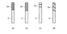
図5(a)に示す液体供給部材3の凹凸面3aは、開口部2aと接する一部の表面にブラスト処理を施してなる。
The concavo-
図5(b)の液体供給部材3の凹凸面3aは、開口部2aと接する一部の表面にローレット仕上げを施した細い溝からなる面である。
The
図5(c)の液体供給部材3の凹凸面3aは、開口部2aと接する一部の表面にリング状の溝を施してなる。形成するリング状溝の数は、液体供給部材3の液体貯蔵室2に対して必要な挿抜力から決めた。
The
図5(d)の液体供給部材3の凹凸面3aは、開口部2aと接する一部の表面に螺旋状の溝を施してなる。
The
なお、液体供給部材3の、液体貯蔵容器2の開口部2aと接合される形状については、凹凸面であれば、上記の図5(a)〜(d)の構成に限るものでない。
In addition, about the shape joined with the
次に、具体的な寸法を挙げて、凹凸面3aを備えた液体供給部材3とこれを接合する液体貯蔵容器2の開口2aについて説明する。
Next, the
液体供給部材3はパイプ形状となっており、内径は、0.32mmで、公差は±0.02mmであり、外径は、0.5mmであって公差は+0、-0.01mmの物を使用した。一方、液体貯蔵容器2の開口部2aに関する寸法値は、開口径0.45mmで公差は+0.01mm、−0.01mmとした。そして、開口部2aに液体供給部材3を圧入して接合した。
The
本発明は、加熱した液体供給部材3の熱が効率よく樹脂に伝達される必要があるので、液体供給部材3の凹凸面3aのくぼみ量(凹溝の深さ)は、開口部2aの樹脂の溶融代の2倍以内が望ましい。
In the present invention, since the heat of the heated
しかる後、液体供給部材3に対し、松下電器産業(株)製/LDソフトビーム装置(YB-15FL1)を用いて加熱を行った。これにより、開口部の樹脂が溶融し液体供給部材3の凹凸面3aと密着し、該樹脂の硬化によって液体供給部材3が固定された。
Thereafter, the
さらに、液体貯蔵容器2にインク供給を行なった後、長期保存(60℃、1ヶ月)、および長期にわたる接続部材(不図示)との接続耐久テスト(20000回)を行った結果、接続部の強度不良による液体供給部材3の抜けや、インクの漏洩などの発生は皆無であった。
Furthermore, after supplying ink to the
(実施形態2)
次に、図6を参照して、本発明の実施形態2について説明する。ここでは、液体供給部材3と液体貯蔵容器2の開口部2aとを接合する別の方法を述べるが、実施形態1と同一の構成部品に同一符号を付けてその説明は割愛する。
(Embodiment 2)
Next,
図6は本発明の実施形態2である液体供給部材と液体貯蔵容器との接合方法について説明した図である。図6では簡単のため液体貯蔵容器2の底面にある液体供給部材3を図の中央に置き、液体貯蔵容器2の底面部のみを拡大して示している。
FIG. 6 is a view for explaining a joining method of the liquid supply member and the liquid storage container according to the second embodiment of the present invention. In FIG. 6, for simplicity, the
図6(a)は液体貯蔵容器2に液体供給部材3を組み付ける前の状態である。この図6(a)における製造手順は、実施形態1の図4(a)と同様である。
FIG. 6A shows a state before the
図6(b)は液体貯蔵容器2に対して液体供給部材3を組み付けている様子を示している。この図は、図6(a)の状態から、押し具12の押し付け力によって液体供給部材3が液体貯蔵容器2の開口部31に挿入(圧入)されている段階である。つまり、液体供給部材3の凹凸面2aが開口部31の内周面に接触しつつ挿入されている状態である。
FIG. 6B shows a state in which the
この状態で実施形態1と同様にソフトビーム加熱を用いて液体供給部材3に向け間接加熱を行う。吸光した液体供給部材3の自己発熱によって、液体貯蔵容器2の開口部31の、液体供給部材3が接触している部分の樹脂が溶融し始める。このとき、液体供給部材3の開口部2aへの挿入を継続している。液体供給部材3は液体貯蔵容器2の開口部2aの一部が溶融された状態で摺動するため、開口部2aの溶融した樹脂が液体供給部材3の凹凸面3aの凹部に深く入り込む。
In this state, indirect heating is performed toward the
図6(c)は液体貯蔵容器2内の所定の位置に液体供給部材3が到達した状態を示している。この図に示すように、液体供給部材3が所定の位置に入った時点で液体供給部材3への間接加熱が終了する。
FIG. 6C shows a state where the
加熱動作が終了すると徐々に溶融した開口部2aの樹脂が再び硬化し始める。
When the heating operation is finished, the resin of the
したがって、液体供給部材3の凹部に深く入り込んだ樹脂は、抜け強度に対してより高くなる。
Therefore, the resin that has entered deeply into the concave portion of the
また、上述した実施形態1及び2の液体貯蔵容器およびその製造方法においては、液体を補充する容器(メインタンク60)に、液体貯蔵容器2の一部に設けられた液体供給部材3とを接続するごとに、液体供給部材3の取り付け強度の低下を招くことがない。
In the liquid storage container and the manufacturing method thereof according to
特に、液体貯蔵容器2の貯蔵部に設けられた開口部2aと液体供給部材3との接合が接着剤等などによる介在部が存在することがないため、介在部の硬化時における接合強度のバラツキ、ならびに長期間の複数回にわたる液体供給部材とを接続する動作時によって、インク接液での介在部の劣化を生じることがない。
In particular, since there is no intervening part due to an adhesive or the like in the connection between the
液体貯蔵容器2の開口部2aと液体供給部材3との接合部分に欠損を生じことなく、液体供給時に液体貯蔵部の気密性が保てる。
The airtightness of the liquid storage unit can be maintained at the time of supplying the liquid without causing a defect in the joint portion between the
以上のように、実施形態1及び2では、インク供給性能を安定させる、液体貯蔵容器の構成および製造方法を提供することができる。
As described above,
(実施形態3)
次に、図7から図11を参照して、本発明の実施形態3について説明する。ここでは、液体供給部材3と液体貯蔵容器2との別の接合構造、及びこの場合の接合方法について述べるが、実施形態1と同一の構成部品に同一符号を付けてその説明は割愛する。
(Embodiment 3)
Next,
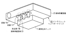
図7は本発明の実施形態3であるインクジェットヘッドカートリッジの概略斜視図、図8は図7の液体貯蔵容器を液体供給部材の位置で切断してみた断面図、図9は図7の液体貯蔵容器にメインタンクよりインクを補充している状態での断面図である。図9中の符号aは、補充されたインク液面の位置を指している。 7 is a schematic perspective view of an inkjet head cartridge according to a third embodiment of the present invention, FIG. 8 is a cross-sectional view of the liquid storage container of FIG. 7 cut at the position of the liquid supply member, and FIG. 9 is a liquid storage of FIG. It is sectional drawing in the state which is replenishing ink from a main tank to a container. The symbol a in FIG. 9 indicates the position of the replenished ink liquid level.
本実施形態では、液体貯蔵容器2の液体供給部材3が接合される底面16に凹部17が形成され、凹部17の底面に液体供給部材3が圧入される圧入孔である開口19が形成されている。
In the present embodiment, a
液体供給部材3が開口19に所定の位置まで圧入された状態で、開口部19の樹脂で熱溶着され、さらに、凹部17内に封止剤18を注入することにより、液体供給部材3が固定されている。封止剤18は底面16に飛び出さないように注入されている。
In a state where the
次に、本実施形態における液体貯蔵容器2と液体供給部材3の接合方法について説明する。図10は本発明の実施形態3である液体供給部材と液体貯蔵容器との接合方法について説明した図である。図10では簡単のため液体貯蔵容器2の底面にある液体供給部材3を図の中央に置き、液体貯蔵容器2の底面部のみを拡大して示している。
Next, a method for joining the
図10(a)は液体貯蔵容器2の開口部19に液体供給部材3を接合させる前の状態を示している。実施形態1,2と同様に、液体供給部材3が保持され、押し具12によって開口部19に圧入可能な装置構成である。
FIG. 10A shows a state before the
図10(b)は液体供給部材3を液体貯蔵容器2に組み付けた状態を示す。このとき、液体供給部材3は開口19に所定の位置まで圧入されるが、圧入後の液体供給部材3の、開口19の内周面に対応する部分には上記の実施形態2,3の構成と異なり、凹凸面を設けていない。が、実施形態2,3の構成と同様に液体供給部材3を凹凸面とすることで、液体供給部材3が抜け強度に対してさらに強くなるので好ましい。
FIG. 10B shows a state in which the
図10(b)に示したように液体供給部材3を開口19に所定の位置まで圧入したら、図10(c)のようにファイバーレンズ13を用いて、液体供給部材3に向けて特定波長のビームを照射する。このように間接的に液体供給部材3を加熱する手段および条件や、液体供給部材3及び液体貯蔵容器2の材料は実施形態1と同じである。
When the
以上のように液体供給部材3に加熱を行うと、吸光した液体供給部材3の自己発熱によって、圧入状態にある相手部分が溶融される。すなわち、液体貯蔵容器2の開口部19の、液体供給部材3との接触部分の樹脂が溶け始める。
When the
このとき、液体貯蔵容器2の開口部19の液体供給部材3との間に抱き込んでいるエアーは膨張して溶融した樹脂を凹部17へ押し出し、盛り上がり21を形成する。
At this time, the air held between the opening 19 of the
上記の加熱動作が終了すると徐々に、溶融した開口部19の樹脂が再び硬化し始める。この硬化とともに、開口部19の樹脂は液体供給部材3を密着固定する。特に盛り上がり21はエアーを巻き込まない溶融した樹脂で形成されているため、液体に対して遮断する効果が出てくる。
When the heating operation is finished, the molten resin in the
その後、図10(d)に示すように、凹部17内に封止剤18を塗布する。このように、盛り上がり21の上から封止剤18としての樹脂を塗布することで確実に液体を遮断して安定化を増すことができる。塗布する樹脂は、封止剤の他に接着剤を使用してもよい。
Thereafter, as shown in FIG. 10 (d), a sealant 18 is applied in the
このとき、溶着時の盛り上がり21、および塗布する封止剤18等の樹脂は凹部17内に収まるようにしてあるため、樹脂が液体貯蔵容器2の底面16から飛び出す事はない。液体貯蔵容器2の底面16の、液体供給部材3の周辺部に突出物が無いので、液体貯蔵容器2とメインタンク60を正常な接続動作でジョイントできる。
At this time, the swell 21 at the time of welding and the resin such as the sealant 18 to be applied are accommodated in the
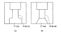
次に、図11を参照して、液体供給部材3を圧入する開口部19の、液体貯蔵容器2の底面16側に設けられる凹部17の形状の例について説明する。
Next, an example of the shape of the
図11(a)及び(b)はそれぞれ凹部17の形状の例を示す。
11 (a) and 11 (b) show examples of the shape of the
図11(a)に示す凹部17は座形状を施したものである。液体供給部材3が圧入される開口部19から座形状に変わる部分が若干のR形状になっているが、これは金型で作り込む上での強度を保つ為の補強である。
The recessed
図11(b)に示す凹部17では、凹部の側面が斜面になっているのが特徴である。
The
その他、開口部19で形成する形状として基準面である底面16より窪んでいればこれに限る物でない。
In addition, the shape formed by the
次に、具体的な寸法を挙げて、液体供給部材3とこれを接合する液体貯蔵容器2の開口2aについて説明する。
Next, the
液体供給部材3はパイプ形状となっており、内径は、0.32mmで、公差は±0.02mmであり、外径は、0.5mmであって公差は+0、-0.01mmの物を使用した。一方、液体貯蔵容器2の開口部19に関する寸法値は、開口径0.45mmで公差は+0.01mm、−0.01mmとした。そして、開口部17に液体供給部材3を圧入して接合した。
The
さらに、凹部17の深さ(底面16からのくぼみ量)は0.5mmとした。 Furthermore, the depth of the concave portion 17 (the amount of depression from the bottom surface 16) was 0.5 mm.
しかる後、液体供給部材3に対し、松下電器産業(株)製/LDソフトビーム装置(YB−15FL1)を用いて加熱を行った。これにより、開口部19の樹脂が溶融し液体供給部材3と密着し、該樹脂の硬化によって液体供給部材3が固定された。このとき、液体貯蔵容器2の開口部19の液体供給部材3との間に抱き込んでいるエアーは膨張して溶融した樹脂を凹部17へ押し出し、盛り上がり21を形成する。盛り上がり21はエアーを巻き込まない溶融した樹脂で形成されているため、液体に対して遮断する効果が発現する。
Thereafter, the
さらに、凹部17内に、封止剤18として熱硬化型エポキシ剤を充填した。封止剤18はインク接液に良好であれば、熱硬化型エポキシ剤に限られない。
Further, a thermosetting epoxy agent was filled as the sealant 18 in the
その後、液体貯蔵容器2にインク供給を行なった後、長期保存(60℃、1ヶ月)、および長期にわたる接続部材(不図示)との接続耐久テスト(20000回)を行った結果、接続部の強度不良による液体供給部材3の抜けや、インクの漏洩などの発生は皆無であった。
Then, after supplying ink to the
上述した実施形態3の液体貯蔵容器及びその製造方法においては、液体供給部材3をより強固に固定する為に熱溶着を使い、熱溶着時の溶着部の盛り上がり21が、液体を補充する容器(メインタンク60)とのジョイント時に干渉しないで正常な接続動作によってインク供給がなされる。
In the liquid storage container and the manufacturing method thereof according to
したがって、液体を補充する容器(メインタンク60)に、液体貯蔵容器の一部に設けられた液体供給部材3とを接続するごとに、液体供給部材3の取り付け強度の低下を招くことがない。
Therefore, every time the
さらにこの場合、液体貯蔵容器2内のインクが、開口部19と液体供給部材3との接合部から漏洩することがないため、インクジェットヘッドカートリッジ外部にインクが漏洩し、場合によってはインク供給を行うシステム全体にインクが漏洩し電気系統のショートなどの致命的な動作不良を発生させる恐れがない。
Further, in this case, since the ink in the
以上のように、本実施形態では、ジョイント性能を安定し、インク漏れの無く信頼性の高い、インクジェットヘッドカートリッジを提供することができる。 As described above, according to the present embodiment, it is possible to provide an ink jet head cartridge with stable joint performance and high reliability without ink leakage.
なお、上述した実施形態1〜3に述べたように、液体供給部材接合部の耐久性が優れるインクジェットヘッドカートリッジは、キャリッジに着脱自在に搭載され、所定の位置にキャリッジがあるときに液体貯蔵容器の筒状の液体供給部材とメインタンクを接続する、いわゆるピットインインク供給方式に好適である。 As described in the first to third embodiments, the ink jet head cartridge with excellent durability of the liquid supply member joint is detachably mounted on the carriage, and the liquid storage container when the carriage is at a predetermined position. This is suitable for a so-called pit-in ink supply system in which a cylindrical liquid supply member and a main tank are connected.
1 液体吐出ヘッド
2 液体貯蔵容器
2a 開口部
3 液体供給部材
3a 凹凸面
5 蓋部材
6 気液分離部材
8 気体連通口(エアー吸引口)
9 連絡室
10 液体貯蔵容器
11 保持具
12 押し具
13 ファイバーレンズ
14 液体漏出防止構造
15 インク
16 底面
17 凹部
18 封止剤
19 開口部
20 液体吸収体
21 盛り上がり
25 接続部材
60 メインタンク
DESCRIPTION OF
9 Communication chamber 10
Claims (10)
前記貯蔵部の一部に設けられた、前記貯蔵部の内部と外部を連通させる開口部と、
前記開口部に装着され、外部容器内の液体を前記貯蔵部内に供給するための液体供給部材とを備え、
前記液体供給部材の、前記開口部の内側面に対応する面が凹凸面である液体貯蔵容器。 A reservoir for storing the liquid;
An opening provided in a part of the storage unit to communicate the inside and the outside of the storage unit;
A liquid supply member attached to the opening and configured to supply liquid in an external container into the storage unit;
A liquid storage container, wherein a surface of the liquid supply member corresponding to an inner surface of the opening is an uneven surface.
前記貯蔵部の面に設けられた凹部と、
前記凹部に設けられ、前記貯蔵部の内部を外部と連通させる開口部と、
前記開口部に装着され、外部容器内の液体を前記貯蔵部内に供給するための液体供給部材とを有する液体貯蔵容器。 A reservoir for storing the liquid;
A recess provided on the surface of the storage unit;
An opening provided in the recess and communicating the inside of the storage with the outside;
A liquid storage container mounted on the opening and having a liquid supply member for supplying the liquid in the external container into the storage.
前記液体供給部材を前記貯蔵部の前記開口部に圧入する段階と、
前記液体供給部材における前記貯蔵部の外側部分を加熱する段階とを有する、液体貯蔵容器の製造方法。 A storage unit that stores liquid, an opening provided in a part of the storage unit, and a liquid supply member that is attached to the opening and supplies liquid in an external container into the storage unit. A method of manufacturing a liquid storage container, wherein when the liquid supply member is joined to the liquid storage container,
Press-fitting the liquid supply member into the opening of the reservoir;
Heating the outer part of the storage part of the liquid supply member.
前記液体供給部材を前記貯蔵部の前記開口部に圧入する段階と、
前記液体供給部材における前記貯蔵部の外側部分を加熱する段階と、を有する、液体貯蔵容器の製造方法。 A storage unit for storing liquid, a recess provided on a part of the surface of the storage unit, an opening provided on a bottom surface of the recess and communicating the inside of the storage unit with the outside, and attached to the opening And a liquid storage container having a liquid supply member for supplying the liquid in the external container into the storage unit, wherein the liquid supply member is joined to the liquid storage container.
Press-fitting the liquid supply member into the opening of the reservoir;
Heating the outer part of the storage part in the liquid supply member.
前記貯蔵部の外面に設けられた凹部と、
前記凹部に設けられ、前記貯蔵部の内部を外部と連通させる開口部と、
前記開口部に装着され、外部容器内の液体を前記貯蔵部内に供給するための
液体供給部材とを有し、前記液体供給部材の前記開口部の内側面に対応する面が凹凸面で形成され、前記凹部内に樹脂が充填されている液体貯蔵容器。 A reservoir for storing the liquid;
A recess provided on the outer surface of the storage unit;
An opening provided in the recess and communicating the inside of the storage with the outside;
A liquid supply member mounted on the opening and configured to supply the liquid in the external container into the storage unit, and a surface corresponding to the inner surface of the opening of the liquid supply member is formed as an uneven surface. A liquid storage container in which the recess is filled with resin.
Priority Applications (1)
| Application Number | Priority Date | Filing Date | Title |
|---|---|---|---|
| JP2004119024A JP2005297436A (en) | 2004-04-14 | 2004-04-14 | Liquid storage container and manufacturing method thereof |
Applications Claiming Priority (1)
| Application Number | Priority Date | Filing Date | Title |
|---|---|---|---|
| JP2004119024A JP2005297436A (en) | 2004-04-14 | 2004-04-14 | Liquid storage container and manufacturing method thereof |
Publications (1)
| Publication Number | Publication Date |
|---|---|
| JP2005297436A true JP2005297436A (en) | 2005-10-27 |
Family
ID=35329563
Family Applications (1)
| Application Number | Title | Priority Date | Filing Date |
|---|---|---|---|
| JP2004119024A Pending JP2005297436A (en) | 2004-04-14 | 2004-04-14 | Liquid storage container and manufacturing method thereof |
Country Status (1)
| Country | Link |
|---|---|
| JP (1) | JP2005297436A (en) |
Cited By (2)
| Publication number | Priority date | Publication date | Assignee | Title |
|---|---|---|---|---|
| CN110774757A (en) * | 2018-07-31 | 2020-02-11 | 精工爱普生株式会社 | Ink-jet printer |
| JP2021030606A (en) * | 2019-08-27 | 2021-03-01 | セイコーエプソン株式会社 | Liquid discharge head unit |
-
2004
- 2004-04-14 JP JP2004119024A patent/JP2005297436A/en active Pending
Cited By (3)
| Publication number | Priority date | Publication date | Assignee | Title |
|---|---|---|---|---|
| CN110774757A (en) * | 2018-07-31 | 2020-02-11 | 精工爱普生株式会社 | Ink-jet printer |
| CN110774757B (en) * | 2018-07-31 | 2022-07-22 | 精工爱普生株式会社 | Inkjet Printers |
| JP2021030606A (en) * | 2019-08-27 | 2021-03-01 | セイコーエプソン株式会社 | Liquid discharge head unit |
Similar Documents
| Publication | Publication Date | Title |
|---|---|---|
| KR100617280B1 (en) | Ink Cartridges and Inkjet Recording Devices | |
| KR100340895B1 (en) | Liquid supply method, liquid supply container, negative pressure generating member container, and liquid container | |
| EP0631874B1 (en) | An ink tank unit, an ink jet cartridge having said ink tank unit and an ink jet apparatus having said ink jet cartridge | |
| JP5950595B2 (en) | TANK AND METHOD FOR MANUFACTURING TANK | |
| JP3450643B2 (en) | Liquid replenishing method for liquid container, liquid ejection recording apparatus using the replenishing method, liquid replenishing container, liquid container, and head cartridge | |
| JPH10250104A (en) | Ink cartridge for ink jet recording apparatus and method of manufacturing the same | |
| US20100257736A1 (en) | Method for manufacturing liquid discharge head | |
| EP1466739B1 (en) | Inkjet recording apparatus and ink cartridge | |
| JP3900117B2 (en) | Method for manufacturing liquid cartridge | |
| US6827430B2 (en) | Liquid container and method of manufacturing liquid container | |
| JP2008001004A (en) | Method for manufacturing liquid supply part of liquid storage container, liquid storage container | |
| JP2006297710A (en) | Liquid storage container, method for manufacturing the same, and inkjet head cartridge | |
| JP2001219572A (en) | Pressurized liquid tank and method of manufacturing the same | |
| JP4048859B2 (en) | Ink cartridge and manufacturing method thereof | |
| JP2009132077A (en) | Ink jet cartridge and method of manufacturing ink jet cartridge | |
| JP4359897B2 (en) | Ink cartridge and manufacturing method thereof | |
| US8403464B2 (en) | Liquid ejecting head and manufacturing method thereof, and liquid ejecting apparatus | |
| JPH02187349A (en) | liquid jet recording head | |
| KR20050116738A (en) | Ink cartridge with porous waterproof sealing member | |
| JP2008114506A (en) | Liquid container and manufacturing method thereof | |
| JP2006240245A (en) | Filter welding method and liquid discharge head cartridge | |
| JP2007237584A (en) | Valve mechanism, valve device, liquid ejecting apparatus, laser welding method, and laser welding assembly | |
| JP4167961B2 (en) | ink cartridge | |
| JP2009184114A (en) | Ink tank and inkjet cartridge | |
| JP2011161779A (en) | Ink cartridge |