JP2005297761A - In-vehicle camera video transmission system - Google Patents
In-vehicle camera video transmission system Download PDFInfo
- Publication number
- JP2005297761A JP2005297761A JP2004116773A JP2004116773A JP2005297761A JP 2005297761 A JP2005297761 A JP 2005297761A JP 2004116773 A JP2004116773 A JP 2004116773A JP 2004116773 A JP2004116773 A JP 2004116773A JP 2005297761 A JP2005297761 A JP 2005297761A
- Authority
- JP
- Japan
- Prior art keywords
- imaging
- transmission system
- connector
- communication
- wireless communication
- Prior art date
- Legal status (The legal status is an assumption and is not a legal conclusion. Google has not performed a legal analysis and makes no representation as to the accuracy of the status listed.)
- Pending
Links
Images

Landscapes
- Closed-Circuit Television Systems (AREA)
- Radio Relay Systems (AREA)
Abstract
【課題】撮像カメラと表示装置とを接続するための通信方式を変更することが容易な車載カメラ映像伝送システムを提供する。
【解決手段】受信装置13と各撮像カメラ11a〜11dとの間の通信に使用される通信方式(有線通信または無線通信)をカメラ制御装置12の構成に影響を与えることなく適宜変更可能となっている。コネクタ132にケーブル140が接続されたときは、信号切替器161a〜161dが切り替わることで有線通信が選択され、コネクタ132にケーブル140が接続されていないときは、信号切替器161a〜161dが切り替わることで、受信器162及びアンテナ164が選択されて無線通信が選択される。
【選択図】図7
An in-vehicle camera video transmission system in which a communication method for connecting an imaging camera and a display device can be easily changed is provided.
A communication method (wired communication or wireless communication) used for communication between a receiving device 13 and each imaging camera 11a to 11d can be appropriately changed without affecting the configuration of the camera control device 12. ing. When the cable 140 is connected to the connector 132, the signal switching devices 161a to 161d are switched to select wired communication. When the cable 140 is not connected to the connector 132, the signal switching devices 161a to 161d are switched. Thus, the receiver 162 and the antenna 164 are selected, and wireless communication is selected.
[Selection] Figure 7
Description
本発明は、主に自動車に搭載される車載カメラ映像伝送システムに関する。 The present invention relates to an in-vehicle camera video transmission system mainly mounted in an automobile.
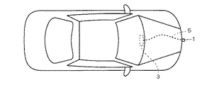
自動車においては、図8の如く、その進行方向やその他の周囲の景観をCCD撮像素子等を利用した撮像カメラ1で撮像し、この撮像カメラ1で撮像された映像を、車室内のインストゥルメントパネル等に設置された表示装置3に表示することが行われている。この場合、撮像カメラ1と表示装置3との間は所定のケーブル5で接続されており、このケーブル5に映像信号を流すことで、撮像カメラ1からの映像が表示装置3に与えられる。
In an automobile, as shown in FIG. 8, the traveling direction and other surrounding scenery are imaged by an
尚、特許文献1のように、撮像カメラ1と表示装置3との間で無線通信を行う技術も公開されている。
As disclosed in
一般に、自動車は電気系統だけでなく、エンジン系統や冷却系統の多くの部品が搭載されている。そして、これらの多くの部品は、重量バランスや機能効率化のために適宜最適な位置に配置される。かかる自動車において、撮像カメラ1と表示装置3との間をケーブル5で接続する場合、そのケーブル5の配策は多くの車両部品のレイアウトによって制約を受ける。例えば、撮像カメラ1を自動車の前端部に設置する場合、通常は自動車の前端部と車室との間にはエンジン機構等の様々な車両部品が搭載されるため、これらの車両部品のレイアウトによってケーブル5の配策が制約を受けることになる。
In general, an automobile is equipped not only with an electric system but also with many parts of an engine system and a cooling system. Many of these components are appropriately arranged at optimal positions for weight balance and functional efficiency. In such an automobile, when the
ところで、量産によるコスト低減を行うために、撮像カメラ1と表示装置3とを規格化する必要があるが、このような規格化された撮像カメラ1及び表示装置3を様々な車種の自動車に搭載する場合、上述のように、車両部品のレイアウトによっては、ケーブル5の配策が容易な場合と困難な場合とが生じ得る。即ち、撮像カメラ1と表示装置3とを接続するケーブル5は、電源用電線、グランド用電線、映像信号用電線の3本の電線が束ねられ、それらをシールドした上で被覆することから、通常のケーブル5はある程度の太さを持った線経を有して形成される。この場合、その曲率半径を小さくするのにはある程度の限界があるため、所望の目的で最適配置された車両部品を回避してケーブル5の屈曲することが困難になる場合が生じ得る。
By the way, in order to reduce the cost by mass production, it is necessary to standardize the
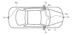
また、自動車によっては、図9のように、複数の撮像カメラ1a〜1dを設置し、それぞれの撮像カメラ1a〜1dで得られた映像を車室内の表示装置3に表示したい場合がある。この場合において、他の車両部品との干渉の問題から、一部の撮像カメラ1a〜1dについてはケーブル5a〜5dでの有線接続が容易であるが、他の一部の撮像カメラ1a〜1dについてはケーブル5a〜5dでの有線接続が困難になる場合も生じ得る。即ち、一台の自動車においても、一部の撮像カメラ1a〜1dを表示装置3に有線接続することが困難になり得る。
Also, depending on the automobile, as shown in FIG. 9, there are cases where a plurality of
その一方において、特許文献1のような無線通信を行う場合、外部から混入される電磁ノイズをどのように除去するかという問題もあり、電磁ノイズの混入を防いで伝送される信号の品質を維持したい場合に、電磁シールドが困難な部位が存在する場合には、一概に無線通信を行うことが困難な場合がある。特に、車両部品のレイアウトによっては、電波経路となる導波管を形成することが困難な場合があり、この場合にはケーブル5の使用が望ましい場合もある。さらに、撮像カメラ1a〜1dの設置位置を変更するために、あるいは、撮像カメラ1a〜1dが設置された自動車の設計変更(ないしは搭載車種の変更)を行うために、撮像カメラ1a〜1dと表示装置3とを接続するための通信方式を変更することを要請される場合もある。しかし、従来の技術においては、通信方式の変更を行う場合に撮像カメラ1a〜1dおよび表示装置3の構成を大幅に変更する必要があった。
On the other hand, when performing wireless communication as in
そこで、本発明の課題は、撮像カメラと表示装置とを接続するための通信方式を変更することが容易な車載カメラ映像伝送システムを提供することにある。 Accordingly, an object of the present invention is to provide an in-vehicle camera video transmission system in which it is easy to change a communication method for connecting an imaging camera and a display device.
上記課題を解決するため、請求項1の発明は、自動車の周囲を撮像するための撮像手段と、前記撮像手段の映像信号を受信する撮像制御手段との間のデータ伝送を行う車載カメラ映像伝送システムにおいて、前記撮像制御手段に接続される中継器を有し、前記中継器が、前記撮像手段との間で信号伝送の媒体となる伝送線路部品を接続するためのコネクタと、前記撮像手段に対して無線通信を行う無線通信手段と、前記撮像制御手段との接続を前記コネクタと前記無線通信手段とに切り換えて、前記撮像手段との間の通信方式を有線通信および無線通信のいずれかに設定する設定手段とを備えることを特徴とする。
In order to solve the above-mentioned problem, the invention of
請求項2の発明は、請求項1に記載の車載カメラ映像伝送システムにおいて、前記中継器は、前記コネクタに対して前記伝送線路部品の接続を検出する検出手段をさらに有し、前記設定手段は、前記検出手段での検出結果に基づいて前記通信方式を有線通信および無線通信のいずれかに設定することを特徴とする。 According to a second aspect of the present invention, in the in-vehicle camera video transmission system according to the first aspect, the repeater further includes a detection unit that detects connection of the transmission line component to the connector, and the setting unit includes: The communication method is set to either wired communication or wireless communication based on the detection result of the detecting means.
請求項3の発明は、請求項2に記載の車載カメラ映像伝送システムにおいて、前記撮像手段が複数個設けられており、前記中継器では、複数個の前記撮像手段の各々に対応して、前記コネクタと前記検出手段と前記設定手段とがひとつずつ設けられ、複数個の前記各検出手段が、当該各検出手段に対応するコネクタへの前記伝送線路部品の接続を検出しているときには、当該各検出手段に対応する設定手段が、前記撮像制御手段との接続を当該各検出手段に対応するコネクタに設定して、当該各検出手段に対応する前記各撮像手段との間の通信方式を有線通信に設定することを特徴とする。 A third aspect of the present invention is the in-vehicle camera video transmission system according to the second aspect, wherein a plurality of the imaging means are provided, and the repeater corresponds to each of the plurality of the imaging means, and When one connector, the detection means, and the setting means are provided, and each of the plurality of detection means detects the connection of the transmission line component to the connector corresponding to the detection means, The setting means corresponding to the detection means sets the connection with the imaging control means to the connector corresponding to each detection means, and the communication method with each imaging means corresponding to each detection means is wired communication. It is characterized by setting to.
請求項4の発明は、請求項3に記載の車載カメラ映像伝送システムにおいて、前記無線通信手段が単一にのみ設けられており、前記無線通信手段が、複数個の前記撮像手段が出力した映像信号を取得可能であることを特徴とする。 According to a fourth aspect of the present invention, in the in-vehicle camera video transmission system according to the third aspect of the present invention, the wireless communication means is provided only in a single unit, and the wireless communication means outputs an image output by a plurality of the imaging means. A signal can be acquired.
請求項5の発明は、請求項1ないし請求項4のいずれかに記載の車載カメラ映像伝送システムにおいて、前記中継器が、前記撮像手段から取得した映像信号を出力する出力端子をさらに備え、前記出力端子が、前記撮像制御手段に形成された入力端子に着脱自在に嵌合可能とされたことを特徴とする。 According to a fifth aspect of the present invention, in the in-vehicle camera video transmission system according to any one of the first to fourth aspects, the repeater further includes an output terminal for outputting a video signal acquired from the imaging means, The output terminal can be detachably fitted to the input terminal formed in the imaging control means.
請求項1ないし請求項5の発明によれば、コネクタに伝送線路部品が接続されているか否かを検出手段が検出し、その検出結果に基づいて有線通信及び無線通信のいずれかが選択されるので、通信方式に応じて撮像制御手段の構成を変更することなく、撮像手段と撮像制御手段との間の通信方式を容易に変更可能である。 According to the first to fifth aspects of the present invention, the detecting means detects whether or not the transmission line component is connected to the connector, and either wired communication or wireless communication is selected based on the detection result. Therefore, the communication method between the image pickup unit and the image pickup control unit can be easily changed without changing the configuration of the image pickup control unit according to the communication method.
請求項3または請求項4の発明によれば、複数個の撮像手段と撮像制御手段との間の通信方式の組合せを容易に変更可能である。 According to invention of Claim 3 or Claim 4, the combination of the communication system between several imaging means and an imaging control means can be changed easily.
請求項4の発明によれば、無線通信手段がひとつしか設けられないので、通信手段の小型化を図ることができる。 According to the invention of claim 4, since only one wireless communication means is provided, the communication means can be reduced in size.
請求項5の発明によれば、通信手段と撮像制御手段との着脱が可能になるので、撮像制御手段に影響を与えることなく、通信手段の変更により通信方式を変更可能になる。 According to the fifth aspect of the present invention, since the communication means and the imaging control means can be attached and detached, the communication method can be changed by changing the communication means without affecting the imaging control means.
○自動車に搭載された車載カメラ映像伝送システムの概略構成;
図1は、実施形態の車載カメラ映像伝送システム10が搭載された自動車AMを上方から見た平面模式図である。以下では、車載カメラ映像伝送システム10の概略について、図1を参照しながら説明する。
○ Schematic configuration of in-vehicle camera video transmission system installed in automobiles;
FIG. 1 is a schematic plan view of an automobile AM on which the in-vehicle camera
自動車AMには周囲を撮像するための例えば4個の撮像カメラ11a〜11dが設置される。撮像カメラ11a〜11dは、それぞれ、自動車の前端部、後端部、左サイドミラー内および右サイドミラー内に設置される。撮像カメラ11a〜11dは、それぞれ、自動車の例えば前方または前方左右、後方、左方下部および右方下部を撮像して映像信号を出力する。
For example, four
さらに、自動車AMには、撮像カメラ11a〜11dを制御するカメラ制御装置12が設けられる。カメラ制御装置12は、中継器である受信装置13を介して撮像カメラ11a〜11dと通信可能となっている。カメラ制御装置12は、撮像カメラ11a〜11dと通信を行うことにより、撮像カメラ11a〜11dが出力した映像信号を取得し、映像表示装置である液晶ディスプレイ15へ出力する。なお、カメラ制御装置12から撮像カメラ11a〜11dへ制御信号を送出できるようにして、撮像カメラ11a〜11dのオンオフ制御や撮影パラメータ制御をカメラ制御装置12が実行できるようにしてもよい。受信装置13と撮像カメラ11a〜11dとの間の通信は、伝送線路部品を利用した有線通信および電磁相互作用を利用した無線通信のいずれかを用いて行われる。ここでいう「伝送線路部品」の典型例は、電気的接続を行うためのケーブルであり、好ましくは、シールド線や同軸ケーブル等のノイズ耐性を有するケーブルである。なお、以下では、電源用電線・グランド用電線・映像信号用電線の3本の電線が束ねられ、それらをシールドした上で被覆されて構成される一般的なケーブルが当該伝送線路部品として使用されているものとして説明を行う。また、無線通信には、例えば、各種デジタル変調が行われた2.4GHz帯の電磁波が用いられる。
Further, the car AM is provided with a
図1においては、撮像カメラ11aと受信装置13との間の通信は無線通信を用いて行われている。一方、撮像カメラ11b〜11dと受信装置13との間の通信はそれぞれ有線通信を用いて行われている。
In FIG. 1, communication between the
なお、上述の説明では、撮像カメラの設置数が4個であるとしたが、撮像カメラの設置数は制限されず、3個以下あるいは5個以上であってもよい。また、受信装置13と各撮像カメラ11a〜11dとの間の通信に使用される通信方式(有線通信または無線通信)をカメラ制御装置12の構成に影響を与えることなく適宜変更可能となっているので、自動車AMの設計変更や車載カメラ映像伝送システム10の搭載車種の変更あるいは撮像カメラ11a〜11dの設置位置の変更によって通信方式を変更する必要を生じても容易に通信方式を変更可能となっている。すなわち、この車載カメラ映像伝送システム10を採用することにより、自動車の設計や搭載車種あるいは撮像カメラの設置位置等の自由度が向上している。
In the above description, the number of installed imaging cameras is four. However, the number of installed imaging cameras is not limited, and may be three or less or five or more. In addition, the communication method (wired communication or wireless communication) used for communication between the
○車載カメラ映像伝送システムの機構構成;
図2〜図5は、それぞれ、カメラ制御装置12、受信装置13、受信装置13と有線通信を行う撮像カメラ(以下では「有線接続撮像カメラ」と略記する)11b〜11dおよび受信装置13と無線通信を行う撮像カメラ(以下では「無線接続撮像カメラ」と略記する)11aの機構構成を示す図である。
○ Mechanism configuration of in-vehicle camera video transmission system;
2 to 5, imaging cameras (hereinafter abbreviated as “wired connection imaging cameras”) 11 b to 11 d and the
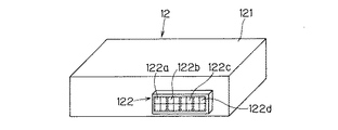
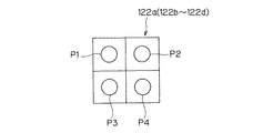
図2に示すように、カメラ制御装置12の筐体121の表面には、受信装置13との機械的および電気的な接続に使用される接続部材として機能するコネクタ122が設けられる。コネクタ122は、撮像カメラ11a〜11dの各々に対応したピン群122a〜122dを備える。ピン群122a〜122dの各々は、例えば、図6のピン群の正面模式図に例示するように、電源用ピンP1・グランド用ピンP2・映像信号用ピンP3およびシールドグランド用ピンP4を備える。電源用ピンP1は、受信装置13に動作電力を供給するために用いられる。映像信号用端子P3は、撮像カメラが出力した映像信号を受信装置13から取得するために用いられる。グランドピンP2およびシールドグランド用ピンP4は、電源用ピンP1および映像信号用ピンP3の基準電位を与える。
As shown in FIG. 2, a
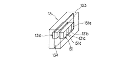
受信装置13は、図3に示すように、カメラ制御装置12のコネクタ122と嵌合可能なコネクタ131を備える。コネクタ131は、コネクタ122と同様のピン配置を有するピン群131a〜131dを有しており、撮像カメラ11a〜11dに係る映像信号を分離してカメラ制御装置12へ出力可能である。また、受信装置13は、撮像カメラ11a〜11dとの間の有線通信用のケーブルを接続するための接続部材であるコネクタ132を備える。コネクタ132は、コネクタ122と同様のピン配置を有しており、有線接続撮像カメラ11b〜11dに係る映像信号の伝送の媒体となるケーブルを接続可能となっている。さらに、受信装置13の筐体133の内部には、撮像カメラ11a〜11dとの無線通信に用いられる受信器およびアンテナを形成した無線基板134が設けられる。当該受信器はベースバンド回路とRF回路とを含んでおり、当該アンテナはパッチアンテナや誘電体アンテナ等である。受信装置133は、無線接続撮像カメラ11aから無線伝送された映像信号を復調する。なお、受信装置13とカメラ制御装置12とをコネクタ122および131によって着脱可能に構成することにより、カメラ制御装置12に影響を与えることなく、通信方式を変更することが可能になる。
As illustrated in FIG. 3, the
なお、上記では、撮像カメラ11b〜11dが有線接続カメラであり、撮像カメラ11aが無線接続カメラであるとして説明を行っているが、受信装置13においては撮像カメラ11a〜11dとの間の通信方式の組合せを任意に設定可能となっている。この点については後述する。
In the above description, the
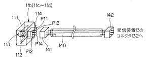
図4に示すように、有線接続撮像カメラ11b〜11dでは、筐体111の内部に回路基板112が設けられる。回路基板112にはCCD素子113が搭載され、撮像が可能となっている。さらに、筐体111には、防水性の4端子のコネクタ114が形成される。コネクタ114には、電源用ピンP11・グランド用ピンP12・映像信号用ピンP13およびシールドグランド用ピンP14が設けられる。有線接続撮像カメラ11b〜11dは、両端にコネクタ141および142が形成されたケーブル140を介して受信装置13のコネクタ132と接続され、受信装置13から動作電力の供給を受けるとともに、映像信号を受信装置13に有線伝送する。
As shown in FIG. 4, in the wired
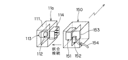
図5に示すように、無線接続撮像カメラ11aは、有線接続撮像カメラ11b〜11dと同じ筐体111、回路基板112、CCD素子113およびコネクタ114を備える。そして、無線接続カメラ11aには、ケーブル140に替えて、無線送信装置150が嵌合接続される。無線送信装置150は、無線接続撮像カメラ11aに対して電源供給を行うとともに、無線接続撮像カメラ11aにおける撮像に係る映像信号を受信装置133で受信可能な電磁波に変換する。
As shown in FIG. 5, the wireless
無線送信装置150は、無線接続撮像カメラ11aのコネクタ114に嵌合接続可能なコネクタ151と、コネクタ151を通じて無線接続撮像カメラ11aから与えられた映像信号を電磁波に変換してアンテナ152を通じて送信する無線回路153とを備える。なお、無線送信装置150は、無線接続撮像カメラ11aに対して電源供給を行う必要があるため、この無線送信装置150から電源線154が引き出されて、自動車の主電源回路に接続される。
The
○受信装置の機能構成;
図7は、受信装置13の機能構成を示すブロック図である。
○ Functional configuration of the receiving device;
FIG. 7 is a block diagram illustrating a functional configuration of the receiving
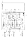
図7に示すように、コネクタ131のピン群131a〜131dの各映像信号ピンP23a〜P23dは、それぞれ、信号切替器(設定手段)161a〜161dに接続される。信号切替器161a〜161dは、電気的な接続状態を2通りに変化させることができる。具体的には、コネクタ132のピン群132a〜132dの各映像信号ピンP33a〜P33dに入力された映像信号を、それぞれ、映像信号ピンP23a〜P23dに出力する第1の接続状態と、後述する受信器162から入力された映像信号を映像信号ピンP23a〜P23dに出力する第2の接続状態とを、後述する接続検出部163a〜163dから与えられた検出信号に応じて切替可能となっている。すなわち、信号切替器161a〜161dは、電気的な接続状態の変更によって、受信装置13と撮像カメラ11a〜11dとの間の通信方式を設定している。
As shown in FIG. 7, the video signal pins P23a to P23d of the
受信装置13は、無線接続撮像カメラ11aが送信した電磁波を取得するアンテナ164と、当該電磁波に係るRF信号に増幅および復調等の信号処理を行って元の映像信号を復元する受信器162とを備える。受信器162は、電磁波に含まれる撮像カメラを特定するIDを利用する等の手段により、復調した映像信号を撮像した撮像カメラを特定可能となっている。さらに、受信器162は、復調した映像信号を、特定した撮像カメラに対応するピン群の映像信号ピンに接続された信号切替器に与える。なお、図7に例示する受信装置13においては、無線通信手段である受信器162およびアンテナ164が多重通信を行っており一系統しか設けられないので、受信装置13を小型に構成可能である。ただし、この点は、受信器を複数系統設けることを妨げるものではない。
The receiving
さらに受信装置13は、ピン群132a〜132dへのケーブル140の接続を各ピン群ごとに独立して検出する接続検出部163a〜163dを備える。接続検出部163a〜163dは、それぞれ、ピン群132a〜132dへのケーブル140の接続を検出すると、信号切替器161a〜161dへ検出信号を出力する。すなわち、受信装置13においては、撮像カメラ11a〜11dの各々に対応して、接続部材であるピン群132a〜132dと接続検出部163a〜163dと信号切替器161a〜161dが設けられる。信号切替器161a〜161dは、当該検出信号を与えられると、接続状態を第1の接続状態に設定して、ケーブル140を介して有線接続撮像カメラから入力された映像信号がカメラ制御装置12へ出力する。このような接続検出部163a〜163dおよび信号切替器161a〜161dにより、撮像カメラと受信装置13とがケーブル140により有線接続されると、撮像カメラと受信装置13との間の通信方式が自動的に有線通信となる。逆に、ケーブル140が接続されない場合、受信装置13は、無線撮像カメラが送信する映像信号を無線通信により自動的に受信してカメラ制御装置12に出力する。
Furthermore, the receiving
なお、ケーブル140の接続の検出は各ピン群132a〜132dにおける電気的状態の変化によって検出可能である。例えば、各ピン群132a〜132dの電源ピンから撮像カメラに供給される電流を監視してケーブル140の接続を検出してもよいし、撮像カメラから入力される映像信号の特定成分を検出することによってケーブル140の接続を検出してもよい。あるいは、コネクタ132に、ケーブル140の接続によって電気的な接続状態が変化するスイッチを併設して、当該スイッチの電気的な接続状態の変化によって、ケーブル140の接続を検出してもよい。
In addition, the detection of the connection of the
また、信号切替器161a〜161dにおける電気的接続状態の変更は、スイッチングダイオードやスイッチングトランジスタによる電気的なスイッチング動作によって行われてもよいし、メカニカルリレーのような機械的なスイッチング動作によって行われてもよい。あるいは、フォトカプラによるスイッチング動作によって行われてもよい。 The change of the electrical connection state in the signal switchers 161a to 161d may be performed by an electrical switching operation using a switching diode or a switching transistor, or may be performed by a mechanical switching operation such as a mechanical relay. Also good. Alternatively, it may be performed by a switching operation by a photocoupler.
このような受信器13の構成により、ケーブル140が接続されると自動的に撮像カメラと受信器13との間で有線通信が確立し、ケーブル140が切り離されると自動的に撮像カメラと受信器との間で無線通信が確立する。すなわち、受信装置13が存在することによって、カメラ制御装置の構成に影響を与えずに自動的に通信方式を変更することが可能になり、撮像カメラの通信方式を容易に変更可能な車載カメラ映像伝送システムを実現することができる。
With such a configuration of the
AM 自動車
10 車載カメラ映像伝送システム
11a〜11d 撮像カメラ
12 カメラ制御装置
113 CCD素子
114,122,131,132,141,142,151 コネクタ
13 受信装置
140 ケーブル
161a〜161d 信号切替器
162 受信器
164 アンテナ
Claims (5)
前記撮像制御手段に接続される中継器を有し、前記中継器が、
前記撮像手段との間で信号伝送の媒体となる伝送線路部品を接続するためのコネクタと、
前記撮像手段に対して無線通信を行う無線通信手段と、
前記撮像制御手段との接続を前記コネクタと前記無線通信手段とに切り換えて、前記撮像手段との間の通信方式を有線通信および無線通信のいずれかに設定する設定手段と
を備えることを特徴とする車載カメラ映像伝送システム。 In an in-vehicle camera video transmission system that performs data transmission between an imaging unit for imaging the surroundings of an automobile and an imaging control unit that receives a video signal of the imaging unit,
Having a repeater connected to the imaging control means, the repeater,
A connector for connecting a transmission line component serving as a signal transmission medium with the imaging means;
Wireless communication means for performing wireless communication with the imaging means;
And a setting unit that switches the connection with the imaging control unit between the connector and the wireless communication unit and sets a communication method with the imaging unit to either wired communication or wireless communication. In-vehicle camera video transmission system.
前記中継器は、前記コネクタに対して前記伝送線路部品の接続を検出する検出手段をさらに有し、
前記設定手段は、前記検出手段での検出結果に基づいて前記通信方式を有線通信および無線通信のいずれかに設定することを特徴とする車載カメラ映像伝送システム。 The in-vehicle camera video transmission system according to claim 1,
The repeater further includes detection means for detecting connection of the transmission line component to the connector,
The in-vehicle camera video transmission system, wherein the setting unit sets the communication method to one of wired communication and wireless communication based on a detection result of the detection unit.
前記撮像手段が複数個設けられており、
前記中継器では、複数個の前記撮像手段の各々に対応して、前記コネクタと前記検出手段と前記設定手段とがひとつずつ設けられ、
複数個の前記各検出手段が、当該各検出手段に対応するコネクタへの前記伝送線路部品の接続を検出しているときには、当該各検出手段に対応する設定手段が、前記撮像制御手段との接続を当該各検出手段に対応するコネクタに設定して、当該各検出手段に対応する前記各撮像手段との間の通信方式を有線通信に設定することを特徴とする車載カメラ映像伝送システム。 The in-vehicle camera video transmission system according to claim 2,
A plurality of the imaging means are provided,
In the repeater, corresponding to each of the plurality of imaging means, the connector, the detection means and the setting means are provided one by one,
When each of the plurality of detection means detects the connection of the transmission line component to the connector corresponding to each detection means, the setting means corresponding to each detection means is connected to the imaging control means. Is set in a connector corresponding to each of the detection means, and a communication system between the imaging means corresponding to the detection means is set to wired communication.
前記無線通信手段が単一にのみ設けられており、
前記無線通信手段が、複数個の前記撮像手段が出力した映像信号を取得可能であることを特徴とする車載カメラ映像伝送システム。 The in-vehicle camera video transmission system according to claim 3,
The wireless communication means is provided only in one,
The in-vehicle camera video transmission system, wherein the wireless communication means can acquire video signals output from a plurality of the imaging means.
前記中継器が、前記撮像手段から取得した映像信号を出力する出力端子をさらに備え、前記出力端子が、前記撮像制御手段に形成された入力端子に着脱自在に嵌合可能とされたことを特徴とする車載カメラ映像伝送システム。
In the vehicle-mounted camera video transmission system according to any one of claims 1 to 4,
The repeater further includes an output terminal for outputting a video signal acquired from the imaging unit, and the output terminal can be detachably fitted to an input terminal formed in the imaging control unit. In-vehicle camera video transmission system.
Priority Applications (1)
| Application Number | Priority Date | Filing Date | Title |
|---|---|---|---|
| JP2004116773A JP2005297761A (en) | 2004-04-12 | 2004-04-12 | In-vehicle camera video transmission system |
Applications Claiming Priority (1)
| Application Number | Priority Date | Filing Date | Title |
|---|---|---|---|
| JP2004116773A JP2005297761A (en) | 2004-04-12 | 2004-04-12 | In-vehicle camera video transmission system |
Publications (1)
| Publication Number | Publication Date |
|---|---|
| JP2005297761A true JP2005297761A (en) | 2005-10-27 |
Family
ID=35329832
Family Applications (1)
| Application Number | Title | Priority Date | Filing Date |
|---|---|---|---|
| JP2004116773A Pending JP2005297761A (en) | 2004-04-12 | 2004-04-12 | In-vehicle camera video transmission system |
Country Status (1)
| Country | Link |
|---|---|
| JP (1) | JP2005297761A (en) |
Cited By (3)
| Publication number | Priority date | Publication date | Assignee | Title |
|---|---|---|---|---|
| KR100952462B1 (en) | 2007-04-27 | 2010-04-13 | 주식회사 아이캔텍 | Video Surveillance System for Simultaneous Remote Control and Local Image Control and Method for Performing Video Surveillance Using the Same |
| JP2022162030A (en) * | 2020-06-23 | 2022-10-21 | アイリスオーヤマ株式会社 | Light emitting unit and lighting device |
| CN116193222A (en) * | 2021-11-26 | 2023-05-30 | 北京三快在线科技有限公司 | UAV Camera System and UAV |
-
2004
- 2004-04-12 JP JP2004116773A patent/JP2005297761A/en active Pending
Cited By (4)
| Publication number | Priority date | Publication date | Assignee | Title |
|---|---|---|---|---|
| KR100952462B1 (en) | 2007-04-27 | 2010-04-13 | 주식회사 아이캔텍 | Video Surveillance System for Simultaneous Remote Control and Local Image Control and Method for Performing Video Surveillance Using the Same |
| JP2022162030A (en) * | 2020-06-23 | 2022-10-21 | アイリスオーヤマ株式会社 | Light emitting unit and lighting device |
| JP7330560B2 (en) | 2020-06-23 | 2023-08-22 | アイリスオーヤマ株式会社 | Light-emitting unit and lighting device |
| CN116193222A (en) * | 2021-11-26 | 2023-05-30 | 北京三快在线科技有限公司 | UAV Camera System and UAV |
Similar Documents
| Publication | Publication Date | Title |
|---|---|---|
| US12184013B2 (en) | Rear camera system for a vehicle with a trailer | |
| US6388881B2 (en) | Vehicle center cluster assembling structure with electrical connection | |
| JP3410192B2 (en) | Wireless communication devices in vehicles | |
| JP2009177785A (en) | In-vehicle wireless communication device and antenna harness | |
| JP2005297761A (en) | In-vehicle camera video transmission system | |
| JP2008211377A (en) | In-vehicle imaging system | |
| JP2011025850A (en) | In-vehicle broadcasting receiving system, and automobile equipped with the same | |
| JP2005306266A (en) | In-vehicle wireless camera device | |
| JP2006067421A (en) | Signal transmission device, camera, connector device, and in-vehicle communication system | |
| JP5220818B2 (en) | Composite component circuit built-in connector and signal path system | |
| JP2008195282A (en) | Vehicle camera device | |
| WO2018143308A1 (en) | Vehicle-mounted antenna device equipped with camera | |
| US10700412B2 (en) | Converter device for adapting an antenna impedance, comprising a housing for a motor vehicle, and motor vehicle with converter device installed therein | |
| JP3048483B2 (en) | Antenna integrated receiver and receiving board | |
| JP2011087166A (en) | Charger, radio terminal, information processing apparatus, cable, and antenna diversity method | |
| JP2005303665A (en) | Camera unit for in-vehicle camera video transmission system | |
| JP2005297760A (en) | In-vehicle camera video transmission system | |
| CN218100259U (en) | Vehicle-mounted video control system and intelligent automobile | |
| CN218513723U (en) | Vehicle-mounted Type-C module and vehicle | |
| CN120686665A (en) | Vehicle-mounted drone control system and vehicle | |
| CN101292431A (en) | Hybrid receiver with adapted front-end and back-end | |
| HK1125507A (en) | Hybrid receiver provided with adaptive front and back terminals | |
| JP3032697U (en) | In-vehicle diversity antenna device | |
| JPH11232598A (en) | Multipurpose information equipment in automobiles | |
| CN118695232A (en) | Vehicle-mounted communication system, switching method of vehicle-mounted communication system, and vehicle |