JP2005297845A - Pneumatic tire - Google Patents
Pneumatic tire Download PDFInfo
- Publication number
- JP2005297845A JP2005297845A JP2004118988A JP2004118988A JP2005297845A JP 2005297845 A JP2005297845 A JP 2005297845A JP 2004118988 A JP2004118988 A JP 2004118988A JP 2004118988 A JP2004118988 A JP 2004118988A JP 2005297845 A JP2005297845 A JP 2005297845A
- Authority
- JP
- Japan
- Prior art keywords
- fitting portion
- block
- pneumatic tire
- fitting
- groove wall
- Prior art date
- Legal status (The legal status is an assumption and is not a legal conclusion. Google has not performed a legal analysis and makes no representation as to the accuracy of the status listed.)
- Pending
Links
- 230000002708 enhancing effect Effects 0.000 abstract 1
- 238000011056 performance test Methods 0.000 description 32
- 238000010998 test method Methods 0.000 description 4
- 206010016173 Fall Diseases 0.000 description 3
- 238000000034 method Methods 0.000 description 3
- 238000011156 evaluation Methods 0.000 description 2
- 230000002457 bidirectional effect Effects 0.000 description 1
- 230000000052 comparative effect Effects 0.000 description 1
- 239000000470 constituent Substances 0.000 description 1
- 230000000694 effects Effects 0.000 description 1
- 238000000465 moulding Methods 0.000 description 1
- 230000002093 peripheral effect Effects 0.000 description 1
- 238000012545 processing Methods 0.000 description 1
- 238000012360 testing method Methods 0.000 description 1
Images





Landscapes
- Tires In General (AREA)
Abstract
Description
この発明は、空気入りタイヤに関し、さらに詳しくは、接地時におけるブロックの剛性を向上させることにより、ブロックの偏摩耗の発生を抑制できる空気入りタイヤに関する。 The present invention relates to a pneumatic tire, and more particularly to a pneumatic tire that can suppress the occurrence of uneven wear of the block by improving the rigidity of the block at the time of ground contact.
スタッドレスタイヤ等では、トラクション性能を向上させるために、トレッド部を構成するブロックに細分化処理やサイピング処理が行われている。かかる構成では、ブロックの剛性が低くなるため、ヒール・アンド・トゥ摩耗などの偏摩耗が発生したり、操縦安定性が悪化したりするという課題がある。 In studless tires and the like, a subdivision process and a siping process are performed on the blocks constituting the tread portion in order to improve the traction performance. In such a configuration, since the rigidity of the block is lowered, there is a problem that uneven wear such as heel and toe wear occurs or steering stability is deteriorated.
かかる課題について、従来の空気入りタイヤには、特許文献1および特許文献2に記載される技術が知られている。特許文献1の空気入りタイヤでは、終端をブロック内に有するサイプがブロックに交互に配置されている。また、特許文献2の空気入りタイヤでは、フォークの先端形状を有するサイプがブロックに配置されている。従来の空気入りタイヤでは、かかるサイピング形状の改良によりブロックの剛性を向上させていた。
Regarding such problems, the techniques described in
しかしながら、これらの従来の空気入りタイヤでは、ブロック内部ではサイプに分断された小ブロックが相互に支え合うことによりブロックの剛性が向上するが、ブロック端部では支え合う小ブロックが無いために剛性が向上しない。このため、ブロック内部とブロック端部とで剛性差が生じて偏摩耗(特に、ヒール・アンド・トゥ摩耗)が発生するという課題があった。 However, in these conventional pneumatic tires, the small blocks divided into sipes support each other inside the block to support each other, but the rigidity of the block is improved because there is no small block to support at the end of the block. Does not improve. For this reason, there is a problem that a difference in rigidity occurs between the inside of the block and the end portion of the block, and uneven wear (particularly heel and toe wear) occurs.
そこで、この発明は、上記に鑑みてされたものであって、接地時におけるブロックの剛性を向上させることにより、ブロックの偏摩耗の発生を抑制できる空気入りタイヤを提供することを目的とする。 Therefore, the present invention has been made in view of the above, and an object of the present invention is to provide a pneumatic tire that can suppress the occurrence of uneven wear of the block by improving the rigidity of the block at the time of ground contact.
上記目的を達成するため、この発明にかかる空気入りタイヤは、トレッド部に主溝および横溝を有すると共に、これらの溝によって区画されて成る複数のブロックを有する空気入りタイヤであって、隣接するブロックの対向する溝壁面には、一方の溝壁面に第一嵌合部が形成されると共に他方の溝壁面に第二嵌合部が形成されており、且つ、前記第一嵌合部および前記第二嵌合部が前記ブロックの接地時にて嵌合することを特徴とする。 In order to achieve the above object, a pneumatic tire according to the present invention is a pneumatic tire having a main groove and a lateral groove in a tread portion and having a plurality of blocks defined by these grooves, and adjacent blocks. The groove surface facing each other has a first fitting portion formed on one groove wall surface and a second fitting portion formed on the other groove wall surface, and the first fitting portion and the first fitting surface The two fitting portions are fitted when the block is grounded.
この空気入りタイヤでは、対向する溝壁面の第一嵌合部および第二嵌合部がブロックの接地時にて嵌合することにより、ブロックが支え合ってブロックの倒れ込みが抑制される。これにより、接地時におけるブロックの剛性が高められるので、ブロックの偏摩耗が抑制される利点がある。 In this pneumatic tire, when the first fitting portion and the second fitting portion of the opposing groove wall surfaces are fitted when the block is grounded, the block is supported and the block is prevented from falling. Thereby, since the rigidity of the block at the time of grounding is improved, there is an advantage that uneven wear of the block is suppressed.
また、この発明にかかる空気入りタイヤは、前記第一嵌合部および前記第二嵌合部が、前記ブロックの踏面に近い位置に形成される。 In the pneumatic tire according to the present invention, the first fitting portion and the second fitting portion are formed at positions close to the tread surface of the block.
この空気入りタイヤでは、第一嵌合部および第二嵌合部が溝壁面上であってブロックの踏面に近い位置に形成される。言い換えると、第一嵌合部および第二嵌合部が、溝壁面上であって、その中腹よりも踏面側に寄った位置に形成される。これにより、摩耗初期におけるブロックの倒れ込みが効果的に抑制される利点がある。 In this pneumatic tire, the first fitting portion and the second fitting portion are formed on the groove wall surface and at a position close to the tread surface of the block. In other words, the first fitting portion and the second fitting portion are formed on the groove wall surface at a position closer to the tread surface side than the middle. Thereby, there exists an advantage by which the fall of the block in the early stage of wear is suppressed effectively.
また、この発明にかかる空気入りタイヤは、前記第一嵌合部および前記第二嵌合部が、前記ブロックの踏面に現れない位置に形成される。 In the pneumatic tire according to the present invention, the first fitting portion and the second fitting portion are formed at positions where they do not appear on the tread surface of the block.
この空気入りタイヤでは、第一嵌合部および第二嵌合部がブロックの踏面に現れない位置に形成されるので、ブロックの摩耗によって当初から嵌合部が削られる事態が抑制される。これにより、ブロックの摩耗初期から相当期間、嵌合部の機能が確保されるので、ブロックの倒れ込みがより効果的に抑制される利点がある。 In this pneumatic tire, since the first fitting portion and the second fitting portion are formed at positions where they do not appear on the tread surface of the block, the situation where the fitting portion is scraped from the beginning due to wear of the block is suppressed. Thereby, since the function of the fitting portion is ensured for a considerable period from the initial wear of the block, there is an advantage that the collapse of the block is more effectively suppressed.
また、この発明にかかる空気入りタイヤは、前記第一嵌合部が、前記溝壁面を窪ませて成る凹部であり、前記第二嵌合部が、前記溝壁面を突出させて成る凸部である。 In the pneumatic tire according to the present invention, the first fitting portion is a concave portion formed by recessing the groove wall surface, and the second fitting portion is a convex portion formed by projecting the groove wall surface. is there.
この空気入りタイヤでは、嵌合部が凹部もしくは凸部により構成される。かかる嵌合部は、その成形が容易である利点がある。 In this pneumatic tire, the fitting portion is constituted by a concave portion or a convex portion. Such a fitting portion has an advantage that its molding is easy.
また、この発明にかかる空気入りタイヤは、前記第二嵌合部の頂部面積S2が、前記第一嵌合部の開口面積S1よりも小さい。 In the pneumatic tire according to the present invention, the top area S2 of the second fitting portion is smaller than the opening area S1 of the first fitting portion.
この空気入りタイヤでは、第二嵌合部の頂部面積S2が第一嵌合部の開口面積S1よりも小さくなるように構成されているので、ブロックの接地時にて、第一嵌合部と第二嵌合部とが好適に嵌合して、ブロックの倒れ込みが効果的に抑制される利点がある。なお、第二嵌合部の頂部面積S2および第一嵌合部の開口面積S1は、0.6≦(S2/S1)≦0.9の関係を満たすことがより好ましい。これにより、第一嵌合部と第二嵌合部とがより好適に嵌合して、ブロックの倒れ込みがより効果的に抑制される利点がある。 In this pneumatic tire, the top area S2 of the second fitting portion is configured to be smaller than the opening area S1 of the first fitting portion. There exists an advantage by which a two fitting part fits suitably and the fall of a block is suppressed effectively. In addition, it is more preferable that the top area S2 of the second fitting portion and the opening area S1 of the first fitting portion satisfy the relationship of 0.6 ≦ (S2 / S1) ≦ 0.9. Thereby, there exists an advantage by which a 1st fitting part and a 2nd fitting part fit more suitably, and the fall of a block is suppressed more effectively.
また、この発明にかかる空気入りタイヤは、前記ブロックが、隣接する前記ブロックの溝壁面に投影されたとき面積を投影面積S3としたときに、前記投影面積S3が、隣接する前記ブロックの溝壁面に形成された第一嵌合部の開口面積S1よりも大きくなるように構成されている。 Further, in the pneumatic tire according to the present invention, when the area of the block is projected onto the groove wall surface of the adjacent block, the projected area S3 is the groove wall surface of the adjacent block. It is comprised so that it may become larger than opening area S1 of the 1st fitting part formed in this.
この空気入りタイヤでは、ブロックの投影面積S3が、第一嵌合部の開口面積S1よりも大きくなるように構成されているので、ブロックの接地時にて、第一嵌合部と第二嵌合部とが好適に嵌合する。これにより、ブロックの倒れ込みがより効果的に抑制される利点がある。なお、ブロックの投影面積S3と、第一嵌合部の開口面積S1とは、0.4≦(S1/S3)の関係を満たすことがより好ましい。これにより、ブロックの接地時にて、第一嵌合部と第二嵌合部とがより好適に嵌合して、ブロックの倒れ込みがより効果的に抑制される利点がある。 In this pneumatic tire, the projected area S3 of the block is configured to be larger than the opening area S1 of the first fitting portion. Therefore, when the block is grounded, the first fitting portion and the second fitting portion are arranged. The part fits suitably. Thereby, there exists an advantage by which the fall of a block is suppressed more effectively. It is more preferable that the projected area S3 of the block and the opening area S1 of the first fitting portion satisfy the relationship of 0.4 ≦ (S1 / S3). Thereby, at the time of grounding of a block, there exists an advantage by which a 1st fitting part and a 2nd fitting part fit more suitably, and the fall of a block is suppressed more effectively.
また、この発明にかかる空気入りタイヤは、前記第二嵌合部の突出高さL2が、隣接する前記ブロック間の距離Gの半分以上の寸法を有する。 In the pneumatic tire according to the present invention, the protruding height L2 of the second fitting portion has a dimension that is more than half of the distance G between the adjacent blocks.
この空気入りタイヤでは、第二嵌合部の突出高さL2が、隣接するブロック間の距離Gの半分以上の寸法を有するので、ブロッの接地時にて、第一嵌合部と第二嵌合部とが好適に嵌合して、ブロックの倒れ込みがより効果的に抑制される利点がある。なお、第一嵌合部の窪み深さL1、第二嵌合部の突出高さL2、および、隣接するブロック間の距離Gは、G/2≦L2<(G+L1)の関係を満たすことが好ましい。これにより、ブロッの接地時にて、第一嵌合部と第二嵌合部とがより好適に嵌合して、ブロックの倒れ込みがより効果的に抑制される利点がある。 In this pneumatic tire, since the protrusion height L2 of the second fitting portion has a dimension that is more than half of the distance G between adjacent blocks, the first fitting portion and the second fitting portion are brought into contact with the block at the time of grounding. There exists an advantage by which a part fits suitably and the fall of a block is suppressed more effectively. Note that the recess depth L1 of the first fitting portion, the protrusion height L2 of the second fitting portion, and the distance G between adjacent blocks satisfy the relationship of G / 2 ≦ L2 <(G + L1). preferable. Thereby, at the time of grounding of a block, there exists an advantage by which a 1st fitting part and a 2nd fitting part fit more suitably, and the fall of a block is suppressed more effectively.
また、この発明にかかる空気入りタイヤは、前記第一嵌合部の窪み深さL1が、第二嵌合部の突出高さL2よりも小さい。 In the pneumatic tire according to the present invention, the recess depth L1 of the first fitting portion is smaller than the protruding height L2 of the second fitting portion.
この空気入りタイヤでは、第一嵌合部の窪み深さL1が、第二嵌合部の突出高さL2よりも小さくなるように構成されているので、ブロックの接地時にて、第一嵌合部と第二嵌合部とが安定的に嵌合して、ブロックの倒れ込みがより効果的に抑制される利点がある。 In this pneumatic tire, since the recess depth L1 of the first fitting portion is configured to be smaller than the protruding height L2 of the second fitting portion, the first fitting is performed when the block is grounded. There exists an advantage by which a part and a 2nd fitting part fit stably, and the fall of a block is suppressed more effectively.
また、この発明にかかる空気入りタイヤは、前記第一嵌合部および前記第二嵌合部が、少なくとも前記ブロックの横溝側の溝壁面に形成される。 In the pneumatic tire according to the present invention, the first fitting portion and the second fitting portion are formed at least on the groove wall surface on the lateral groove side of the block.
この空気入りタイヤでは、第一嵌合部および第二嵌合部がブロックの横溝側、すなわちタイヤ周方向側の壁面に形成されるので、接地時にて、これらの嵌合部が嵌合することにより、ブロックがタイヤ周方向に結合される。これにより、ブロックのタイヤ周方向にかかる倒れ込みが抑制されるので、ブロックのヒール・アンド・トゥ摩耗が効果的に抑制される利点がある。 In this pneumatic tire, the first fitting portion and the second fitting portion are formed on the lateral groove side of the block, that is, on the wall surface on the tire circumferential direction side. Thus, the blocks are coupled in the tire circumferential direction. As a result, since the falling of the block in the tire circumferential direction is suppressed, there is an advantage that the heel and toe wear of the block is effectively suppressed.
また、この発明にかかる空気入りタイヤは、前記第一嵌合部および前記第二嵌合部が、タイヤ周方向に配列された全ての前記ブロック間に形成される。 In the pneumatic tire according to the present invention, the first fitting portion and the second fitting portion are formed between all the blocks arranged in the tire circumferential direction.
この空気入りタイヤでは、第一嵌合部および第二嵌合部が、タイヤ周方向に配列された少なくとも1列の全てのブロック間に形成されているので、接地時にて、接地したブロック群間のすべての第一嵌合部および第二嵌合部が嵌合する。これにより、接地したブロック群が一体となって支え合うので、ブロックの倒れ込みがより効果的に抑制される。 In this pneumatic tire, the first fitting portion and the second fitting portion are formed between all the blocks in at least one row arranged in the tire circumferential direction. All the first fitting parts and the second fitting parts are fitted. Thereby, since the grounded block group supports each other, the collapse of the block is more effectively suppressed.
この発明にかかる空気入りタイヤによれば、対向する溝壁面の第一嵌合部および第二嵌合部がブロックの接地時にて嵌合することにより、ブロックが支え合ってブロックの倒れ込みが抑制されるので、接地時におけるブロックの剛性が高められて、ブロックの偏摩耗が抑制される利点がある。 According to the pneumatic tire according to the present invention, the first fitting portion and the second fitting portion of the opposing groove wall surfaces are fitted when the block is grounded, so that the block supports each other and collapse of the block is suppressed. Therefore, there is an advantage that the rigidity of the block at the time of ground contact is increased and uneven wear of the block is suppressed.
以下、この発明につき図面を参照しつつ詳細に説明する。なお、この実施例によりこの発明が限定されるものではない。また、以下に示す実施例の構成要素には、当業者が置換可能かつ容易なもの、或いは実質的同一のものが含まれる。 Hereinafter, the present invention will be described in detail with reference to the drawings. Note that the present invention is not limited to the embodiments. In addition, constituent elements of the embodiments described below include those that can be easily replaced by those skilled in the art or those that are substantially the same.
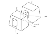
図1は、この発明の実施例1にかかる空気入りタイヤを示す平面図である。図2〜図4は、図1に記載した空気入りタイヤのブロックを示す斜視図(図2)、平面図(図3)および側面図(図4)である。図5は、図1に記載したブロックの作用を示す側面図である。 1 is a plan view showing a pneumatic tire according to a first embodiment of the present invention. 2 to 4 are a perspective view (FIG. 2), a plan view (FIG. 3), and a side view (FIG. 4) showing the block of the pneumatic tire shown in FIG. FIG. 5 is a side view showing the operation of the block shown in FIG.
この空気入りタイヤ1は、トレッド部に主溝2および横溝3を有すると共に、これらの溝2、3によって区画されて成る複数のブロック4を有する。この空気入りタイヤ1では、隣接するブロック4、4間の対向する溝壁面に、嵌合部41、42が形成されている。そして、ブロック4の接地時にて、これらの嵌合部41、42が嵌合することにより、ブロック4の倒れ込みが抑制されてブロック4の剛性が向上する点に特徴を有する。
The
ブロック4の嵌合部41、42は、第一嵌合部41および第二嵌合部42から成る(図2参照)。第一嵌合部41は、隣接するブロック4、4間の対向する溝壁面のうち一方の溝壁面に形成され、この溝壁面を窪ませて成る凹部により構成される。第二嵌合部42は、他方の溝壁面に形成され、この溝壁面を突出させて成る凸部により構成される。なお、かかる凹部および凸部から成る嵌合部41、42は、その成形が容易である。また、第一嵌合部41および第二嵌合部42は、ブロック4、4の横溝3側、すなわちタイヤ周方向側の溝壁面に形成されている。また、第一嵌合部41および第二嵌合部42は、タイヤ周方向に隣接するブロック4、4間にて対となるように構成されており、組合わさったときに相互に嵌合する形状および寸法を有する(図3参照)。また、第一嵌合部41および第二嵌合部42は、ブロック4の踏面に現れないように、溝壁面の中腹(ブロック高さの途中)に設けられている(図4参照)。
The
この空気入りタイヤ1では、トレッド部(ブロック4の踏面)の接地時にて、ブロック4が接地圧により潰れて幅方向に膨らむと、溝幅が狭まることにより、隣接するブロック4、4の第一嵌合部41および第二嵌合部42が組合わさって嵌合する(図5参照)。そして、これらの嵌合部41、42を介してブロック4、4同士が支え合うことにより、ブロック4の倒れ込みが抑制される。
In this
また、この空気入りタイヤ1では、第一嵌合部41および第二嵌合部42が、ブロックの接地時にて嵌合し(図5参照)、ブロック4の高さ方向および幅方向の双方向に対して係合するように構成されている。かかる構成では、嵌合部41、42の嵌合によって、接地時における溝壁面の平面方向への位置ズレ、特に、ブロック4の高さ方向への位置ズレが抑制される。これにより、ブロック4の倒れ込みがより効果的に抑制される。
In the
また、この空気入りタイヤ1では、第一嵌合部41および第二嵌合部42がブロック4の横溝3側の溝壁面に形成されている。かかる構成では、接地時にて、これらの嵌合部41、42が嵌合することにより、ブロック4がタイヤ周方向に結合される。これにより、ブロック4のタイヤ周方向にかかる倒れ込みが抑制されるので、ブロック4のヒール・アンド・トゥ摩耗が効果的に抑制される利点がある。
In the
また、この空気入りタイヤ1では、第一嵌合部41および第二嵌合部42が、タイヤ周方向に配列された全てのブロック4、4間に形成されている(図1〜図4参照)。言い換えると、タイヤ周方向に隣接するブロック4、4のすべての溝壁面には、対向する溝壁面の一方に第一嵌合部41が形成され、他方に第二嵌合部42が形成されている。かかる構成では、接地したブロック4群間のすべての第一嵌合部41および第二嵌合部42が嵌合して、これらのブロック4群があたかも一本のリブとなるように機能する。これにより、接地したブロック4群が一体となって支え合い、ブロック4の倒れ込みがより効果的に抑制される。
Moreover, in this
この空気入りタイヤ1によれば、接地時にて、ブロック4の嵌合部41、42が嵌合することによりブロック4の倒れ込みが抑制されるので、接地時におけるブロック4の剛性が高められ、また、トレッド部の接地面積が維持される。これにより、タイヤのトラクション性能や操縦安定性が向上すると共に、ブロック4の偏摩耗(特に、ヒール・アンド・トゥ摩耗)が抑制される利点がある。
According to this
なお、この空気入りタイヤ1では、嵌合部41、42が、溝壁面上であってブロック4の踏面(トレッド部の表面)に近い位置に形成されている(図4参照)。かかる構成は、摩耗初期におけるブロック4の倒れ込みが効果的に抑制される点で好ましい。具体的には、嵌合部41、42が、溝壁面上であって、その中腹よりも踏面側に寄った位置に形成されることが好ましい。また、嵌合部41、42が、溝壁面上であって、ブロック4の高さの50[%]以上の位置に形成されることがより好ましい。
In the
しかし、これに限らず、嵌合部41、42が溝壁面上のいずれの位置に形成されていても良い。例えば、嵌合部41、42は、接地時にてブロック4が潰れたときに、溝壁面上であってブロック4が最も膨らむ位置に形成されることが好ましい。これにより、ブロック4が潰れたときに嵌合部41、42が嵌合し易くなるので、ブロック4の倒れ込みがより効果的に抑制される利点がある。
However, the present invention is not limited to this, and the
また、この空気入りタイヤ1では、嵌合部41、42がブロック4の踏面に現れないように形成される(図4参照)。かかる構成では、ブロック4の摩耗によって当初から嵌合部41、42が削られる事態が抑制されるので、ブロック4の摩耗初期から中期に渡って相当期間、嵌合部41、42の機能が確保される。また、ブロック4の高さ方向にかかる嵌合部41、42の嵌合が確保されるので、高さ方向への溝壁面間の位置ズレないしは滑りが抑制される。これにより、ブロック4の倒れ込みがより効果的に抑制される利点がある。しかし、これに限らず、嵌合部41、42がブロック4の踏面に現れるように形成されていても良い(図示省略)。
Moreover, in this
なお、当初は嵌合部41、42がブロック4の踏面に現れていなくとも、ブロック4の摩耗により、いずれは嵌合部41、42がブロック4の踏面に現れる。しかし、ある程度ブロック4が摩耗した段階では、ブロック4の高さが低くなるためにブロック4の剛性が向上している。したがって、かかる段階では、嵌合部41、42の機能が不要となるため、何ら問題が生じない。
Even if the
また、この空気入りタイヤ1では、第二嵌合部42が略四角柱形状の凸部により構成されており、第一嵌合部41がかかる凸部に対応した凹部により構成されている(図1〜図5参照)。かかる構成は、これらの嵌合部41、42が嵌合したときに溝壁面の平面方向(ブロック4の高さ方向および幅方向)にしっかりと組み合い、ブロック4の倒れ込みが効果的に抑制される点で好ましい。
Moreover, in this
しかし、これに限らず、第一嵌合部41および第二嵌合部42の形状は、これらの作用や加工容易性に基づいて、当業者自明の範囲内で選択され得る。例えば、第二嵌合部42が他の角柱形状、円柱形状、錘形状、半球形状その他の形状を有する凸部から成り、第一嵌合部41がかかる凸部に対応した凹部により構成されても良い(図示省略)。
However, the present invention is not limited to this, and the shapes of the first
図6は、この発明の実施例2にかかる空気入りタイヤの性能試験の結果を示す表である。この実施例2の空気入りタイヤ1において、上記実施例1の空気入りタイヤ1と同一の構成要素には同一の符号を付し、その説明を省略する。
FIG. 6 is a table showing the results of the performance test of the pneumatic tire according to Example 2 of the present invention. In the
この空気入りタイヤ1では、ブロック4、4の間隔(横溝3の溝幅)Gが6[mm]、第一嵌合部41の窪み深さL1が1[mm]、第二嵌合部42の高さL2が4[mm]となるように構成される(図3および図4参照)。また、主溝2および横溝3の溝深さは、いずれも18.5[mm]である。
In this
なお、第一嵌合部41の窪み深さL1とは、溝壁面に対する第一嵌合部41の深さであり、トレッド部を平面視したときの踏面端部からの凹量を意味する。また、第二嵌合部42の突出高さL2とは、溝壁面に対する第二嵌合部42の高さであり、トレッド部を平面視したときの踏面端部からの凸量を意味する。また、ブロック4、4間の距離Gは、ブロック4、4間の溝幅でもある。
In addition, the hollow depth L1 of the first
図6に示す性能試験では、空気入りタイヤ1が、11R22.5 14PRのタイヤサイズを有し、JATMAの正規条件に従ってリム組みされて、最大内圧および最大荷重を負荷されている。そして、この空気入りタイヤ1について、(1)耐偏摩耗性能および(2)制動性能(制動距離)について試験を行った。
In the performance test shown in FIG. 6, the
(1)耐偏摩耗性能の試験では、空気入りタイヤ1が装着された車両を舗装道路にて3万[km]の走行させて、ブロック4のヒール・アンド・トゥ摩耗の発生量について指数評価を行った。また、(2)制動性能試験では、空気入りタイヤ1が装着された車両について、40[km/h]での走行時にてブレーキングを開始し、制動距離を測定して指数評価を行った。また、制動性能試験は、路面状態がドライ(路面温度25[度])およびスノー(圧雪路。路面温度0[度]。)の場合について行った。なお、これらの指数評価は、従来例を基準(100)として表示されており、いずれも数値が大きいほど好ましい。
(1) In the uneven wear resistance test, a vehicle equipped with
図6に示すように、この空気入りタイヤ1は、嵌合部41、42を有しない従来の空気入りタイヤ(従来例)と比較して、耐偏摩耗性能および制動性能(ドライおよびスノー)のいずれについても向上していることが分かる。
As shown in FIG. 6, the
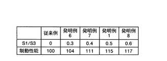
図7は、この発明の実施例3にかかる空気入りタイヤのブロックを示す説明図である。図8は、図7に記載した空気入りタイヤの性能試験の結果を示す表である。この実施例3にかかる空気入りタイヤにおいて、上記実施例1および実施例2の空気入りタイヤ1と同一の構成要素には同一の符号を付し、その説明を省略する。
FIG. 7 is an explanatory view showing a pneumatic tire block according to
この空気入りタイヤ1では、第二嵌合部42の頂部面積S2が、第一嵌合部41の開口面積S1よりも小さくなるように構成されている(図7参照)。また、第二嵌合部42が、嵌合時にて安定的に第一嵌合部41に付勢できる程度の頂部面積S2を有する。具体的には、第一嵌合部41の開口面積S1と、第二嵌合部42の頂部面積S2とが、0.6≦(S2/S1)≦0.9の関係を満すことが好ましい。これにより、ブロック4の接地時にて、第一嵌合部41と第二嵌合部42とが好適に嵌合して、ブロック4の倒れ込みが効果的に抑制される利点がある。
In the
図8に示す性能試験では、空気入りタイヤ1が、11R22.5 14PRのタイヤサイズを有し、JATMAの正規条件に従ってリム組みされて、最大内圧および最大荷重を負荷されている。この性能試験では、第一嵌合部41の開口面積S1の値、および、第二嵌合部42の頂部面積S2の値を変更して制動性能試験(ドライ)を行い、空気入りタイヤ1の制動性能について評価を行った。なお、この制動性能試験にかかる試験方法は、実施例2の場合と同様である。
In the performance test shown in FIG. 8, the
図8に示すように、この空気入りタイヤ1は、嵌合部41、42を有しない従来の空気入りタイヤ(従来例)と比較して、制動性能が向上していることが分かる。また、第一嵌合部41の開口面積S1と、第二嵌合部42の頂部面積S2とが0.6≦(S2/S1)≦0.9の関係を満たすときに、より高い制動性能が得られることが分かる(発明例1、3、4、5参照)。
As shown in FIG. 8, it can be seen that the
図9−1及び図9−2は、この発明の実施例4にかかる空気入りタイヤのブロックを示す説明図である。図10は、図9−1及び図9−2に記載した空気入りタイヤの性能試験の結果を示す表である。この実施例4の空気入りタイヤ1において、上記実施例1〜実施例3の空気入りタイヤ1と同一の構成要素には同一の符号を付し、その説明を省略する。
FIGS. 9-1 and FIGS. 9-2 are explanatory drawings which show the block of the pneumatic tire concerning Example 4 of this invention. FIG. 10 is a table showing the results of the performance test of the pneumatic tire depicted in FIGS. 9-1 and 9-2. In the
この空気入りタイヤ1では、ブロック4が隣接するブロック4の溝壁面に投影されたとき面積を投影面積S3としたときに、この投影面積S3が、第一嵌合部41の開口面積S1よりも大きくなるように構成されている(図9−1及び図9−2参照)。具体的には、ブロック4の投影面積S3と、第一嵌合部41の開口面積S1とが、0.4≦(S1/S3)の関係を満たすことが好ましい。これにより、ブロック4の接地時にて、第一嵌合部41と第二嵌合部42とが好適に嵌合して、ブロック4の倒れ込みがより効果的に抑制される利点がある。なお、投影面積S3は、隣接するブロック4、4が直線的に配列されている場合にはブロック4の溝壁面の面積と等しくなり(図9−1参照)、隣接するブロック4、4が斜めに配列されている場合には投影されたブロック4の面積と等しくなる(図9−2参照)。
In this
図10に示す性能試験では、空気入りタイヤ1が、11R22.5 14PRのタイヤサイズを有し、JATMAの正規条件に従ってリム組みされて、最大内圧および最大荷重を負荷されている。この性能試験では、第一嵌合部41の開口面積S1の値、および、ブロック4の投影面積S3の値を変更して制動性能試験を行い、空気入りタイヤ1の制動性能(ドライ)について評価を行った。
In the performance test shown in FIG. 10, the
なお、この制動性能試験にかかる試験方法は、実施例2の場合と同様である。また、この制動性能試験では、第一嵌合部41の開口面積S1と、第二嵌合部42の頂部面積S2とが(S2/S1)=0.9の関係を満たすように構成されている。
The test method for this braking performance test is the same as that in the second embodiment. In this braking performance test, the opening area S1 of the first
図10に示すように、この空気入りタイヤ1は、嵌合部41、42を有しない従来の空気入りタイヤ(従来例)と比較して、制動性能が向上していることが分かる。また、ブロック4の投影面積S3と、第一嵌合部41の開口面積S1とが、0.4≦(S1/S3)の関係を満たすときに、より高い制動性能が得られることが分かる(発明例1、7、8参照)。
As shown in FIG. 10, it can be seen that this
図11は、この発明の実施例5にかかる空気入りタイヤの性能試験の結果を示す表である。この実施例5の空気入りタイヤ1において、上記実施例1〜実施例4の空気入りタイヤ1と同一の構成要素には同一の符号を付し、その説明を省略する。
FIG. 11 is a table showing the results of the performance test of the pneumatic tire according to Example 5 of the present invention. In the
この空気入りタイヤ1では、第二嵌合部の突出高さL2が、隣接するブロック4、4間の距離Gの半分以上の寸法を有するように構成されている。具体的には、第一嵌合部41の窪み深さL1、第二嵌合部の突出高さL2、および、隣接するブロック4、4間の距離Gが、G/2≦L2<(G+L1)の関係を満たすように構成されている(図2および図3参照)。かかる構成とすれば、ブロック4の接地時にて、第一嵌合部41と第二嵌合部42とが好適に嵌合して、ブロック4の倒れ込みがより効果的に抑制される利点がある。
In this
図11に示す性能試験では、空気入りタイヤ1が、11R22.5 14PRのタイヤサイズを有し、JATMAの正規条件に従ってリム組みされて、最大内圧および最大荷重を負荷されている。この性能試験では、第一嵌合部41の窪み深さL1の値を1[mm]に固定し、第二嵌合部42の突出高さL2の値を変更して制動性能試験を行い、空気入りタイヤ1の制動性能(ドライ)について評価を行った。
In the performance test shown in FIG. 11, the
なお、この制動性能試験にかかる試験方法は、実施例2の場合と同様である。また、この制動性能試験では、第一嵌合部41の開口面積S1と、第二嵌合部42の頂部面積S2とが(S2/S1)=0.9の関係を満たすように構成されている。また、ブロック4の投影面積S3と、第一嵌合部41の開口面積S1とが、(S1/S3)=0.5の関係を満たすように構成されている。また、溝深さは、18.5[mm]である。
The test method for this braking performance test is the same as that in the second embodiment. In this braking performance test, the opening area S1 of the first
図11に示すように、この空気入りタイヤ1は、嵌合部41、42を有しない従来の空気入りタイヤ(従来例)と比較して、制動性能が向上していることが分かる。また、第一嵌合部41の窪み深さL1、第二嵌合部の突出高さL2、および、対向するブロック4、4間の距離Gが、G/2≦L2<(G+L1)の関係を満たすときに、より高い制動性能が得られることが分かる(発明例1、10、11参照)。
As shown in FIG. 11, it can be seen that the
図12は、この発明の実施例6にかかる空気入りタイヤの性能試験の結果を示す表である。この実施例6の空気入りタイヤ1において、上記実施例1〜実施例5の空気入りタイヤ1と同一の構成要素には同一の符号を付し、その説明を省略する。
FIG. 12 is a table showing the results of the performance test of the pneumatic tire according to Example 6 of the present invention. In the
この空気入りタイヤ1では、第一嵌合部41の窪み深さL1が、第二嵌合部42の突出高さL2よりも小さくなるように構成されている(図2および図3参照)。すなわち、第一嵌合部41の窪み深さL1、および、第二嵌合部42の突出高さL2が、0<L1<L2の関係を満たす。かかる構成とすれば、ブロック4の接地時にて、第一嵌合部41と第二嵌合部42とが安定的に嵌合して、ブロック4の倒れ込みがより効果的に抑制される利点がある。
The
図12に示す性能試験では、空気入りタイヤ1が、11R22.5 14PRのタイヤサイズを有し、JATMAの正規条件に従ってリム組みされて、最大内圧および最大荷重を負荷されている。この性能試験では、第二嵌合部42の突出高さL2の値を4[mm]に固定し、第一嵌合部41の窪み深さL1の値を変更して制動性能試験を行い、空気入りタイヤ1の制動性能(ドライ)について評価を行った。
In the performance test shown in FIG. 12, the
なお、この制動性能試験にかかる試験方法は、実施例2の場合と同様である。また、この制動性能試験では、第一嵌合部41の開口面積S1と、第二嵌合部42の頂部面積S2とが(S2/S1)=0.9の関係を満たすように構成されている。また、ブロック4の投影面積S3と、第一嵌合部41の開口面積S1とが、(S1/S3)=0.5の関係を満たすように構成されている。また、溝深さは、18.5[mm]である。
The test method for this braking performance test is the same as that in the second embodiment. In this braking performance test, the opening area S1 of the first
図12に示すように、この空気入りタイヤ1は、第一嵌合部41の窪み深さL1が0[mm]の空気入りタイヤ(比較例4)と比較して、制動性能が向上していることが分かる(発明例1、12、13参照)。
As shown in FIG. 12, this
図13および図14は、この発明の実施例7にかかる空気入りタイヤのブロックを示す説明図である。これらの図において、上記実施例1の空気入りタイヤ1と同一の構成要素には同一の符号を付し、その説明を省略する。
13 and 14 are explanatory views showing blocks of a pneumatic tire according to Example 7 of the present invention. In these drawings, the same components as those of the
この空気入りタイヤ1では、第一嵌合部41および第二嵌合部42が、ブロック4の幅と同一幅に形成されている。かかる構成では、ブロック4の接地時にて第一嵌合部41と第二嵌合部42とが嵌合したときに、これらの嵌合部41、42がブロック4の高さ方向(溝深さ方向)に組み合ってブロック4の倒れ込みが抑制される(図示省略。図5参照)。これにより、接地時におけるブロック4の剛性が高められ、また、トレッド部の接地面積が維持されるので、タイヤのトラクション性能や操縦安定性が向上すると共に、ブロック4の偏摩耗が抑制される利点がある。
In the
図15は、この発明の実施例8にかかる空気入りタイヤのブロックを示す説明図である。同図において、上記実施例1の空気入りタイヤ1と同一の構成要素には同一の符号を付し、その説明を省略する。
FIG. 15 is an explanatory view showing a pneumatic tire block according to
この空気入りタイヤ1では、第一嵌合部41および第二嵌合部42が、ブロック4の主溝2側の溝壁面にも形成されている。すなわち、隣接するブロック4、4が、主溝2側の溝壁面(および横溝3側の溝壁面)に第一嵌合部41もしくは第二嵌合部42を有しており、且つ、主溝2(および横溝3)を挟んで対向するブロック4、4間にて、これらの嵌合部41、42が相互に嵌合するように対となって構成されている。
In the
かかる構成では、ブロック4の接地時したときに、主溝2側および横溝3側の双方の溝壁面にて第一嵌合部41と第二嵌合部42とが嵌合する(図示省略)。したがって、かかる構成では、ブロック4がトレッド部の周方向および幅方向にて相互に組み合うので、ブロック4の倒れ込みがより効果的に抑制される。特に、ブロック4の幅方向にかかる倒れ込みが抑制される。これにより、接地時におけるブロック4の剛性が高められ、また、トレッド部の接地面積が維持されるので、タイヤのトラクション性能や操縦安定性が向上すると共に、ブロック4の偏摩耗が抑制される利点がある。
In such a configuration, when the
以上のように、本発明にかかる空気入りタイヤは、接地時におけるブロックの剛性を向上させることにより、ブロックの偏摩耗の発生を抑制できる点で有用である。 As described above, the pneumatic tire according to the present invention is useful in that it can suppress the occurrence of uneven wear of the block by improving the rigidity of the block at the time of ground contact.
1 空気入りタイヤ
2 主溝
3 横溝
4 ブロック
41 第一嵌合部
42 第二嵌合部
S1 嵌合部の開口面積
S2 頂部面積
S3 投影面積
G ブロック間の距離
DESCRIPTION OF
Claims (10)
隣接するブロックの対向する溝壁面には、一方の溝壁面に第一嵌合部が形成されると共に他方の溝壁面に第二嵌合部が形成されており、且つ、前記第一嵌合部および前記第二嵌合部が前記ブロックの接地時にて嵌合することを特徴とする空気入りタイヤ。 A pneumatic tire having a main groove and a lateral groove in a tread portion and having a plurality of blocks defined by these grooves,
A first fitting portion is formed on one groove wall surface and a second fitting portion is formed on the other groove wall surface, and the first fitting portion is formed on an opposite groove wall surface of an adjacent block. The pneumatic tire is characterized in that the second fitting portion is fitted when the block is grounded.
前記投影面積S3が、隣接する前記ブロックの溝壁面に形成された第一嵌合部の開口面積S1よりも大きくなるように構成されている請求項4または5に記載の空気入りタイヤ。 When the area is projected area S3 when the block is projected onto the groove wall surface of the adjacent block,
The pneumatic tire according to claim 4 or 5, wherein the projected area S3 is configured to be larger than an opening area S1 of a first fitting portion formed on a groove wall surface of the adjacent block.
Priority Applications (1)
| Application Number | Priority Date | Filing Date | Title |
|---|---|---|---|
| JP2004118988A JP2005297845A (en) | 2004-04-14 | 2004-04-14 | Pneumatic tire |
Applications Claiming Priority (1)
| Application Number | Priority Date | Filing Date | Title |
|---|---|---|---|
| JP2004118988A JP2005297845A (en) | 2004-04-14 | 2004-04-14 | Pneumatic tire |
Publications (1)
| Publication Number | Publication Date |
|---|---|
| JP2005297845A true JP2005297845A (en) | 2005-10-27 |
Family
ID=35329905
Family Applications (1)
| Application Number | Title | Priority Date | Filing Date |
|---|---|---|---|
| JP2004118988A Pending JP2005297845A (en) | 2004-04-14 | 2004-04-14 | Pneumatic tire |
Country Status (1)
| Country | Link |
|---|---|
| JP (1) | JP2005297845A (en) |
Cited By (4)
| Publication number | Priority date | Publication date | Assignee | Title |
|---|---|---|---|---|
| WO2007148694A1 (en) * | 2006-06-19 | 2007-12-27 | Bridgestone Corporation | Pneumatic tire |
| WO2013114852A1 (en) * | 2012-02-01 | 2013-08-08 | 株式会社ブリヂストン | Pneumatic tire |
| WO2016072133A1 (en) * | 2014-11-05 | 2016-05-12 | 株式会社ブリヂストン | Pneumatic tire |
| JP2021195047A (en) * | 2020-06-16 | 2021-12-27 | 住友ゴム工業株式会社 | tire |
-
2004
- 2004-04-14 JP JP2004118988A patent/JP2005297845A/en active Pending
Cited By (10)
| Publication number | Priority date | Publication date | Assignee | Title |
|---|---|---|---|---|
| WO2007148694A1 (en) * | 2006-06-19 | 2007-12-27 | Bridgestone Corporation | Pneumatic tire |
| JPWO2007148694A1 (en) * | 2006-06-19 | 2009-11-19 | 株式会社ブリヂストン | Pneumatic tire |
| US8191591B2 (en) | 2006-06-19 | 2012-06-05 | Bridgestone Corporation | Pneumatic tire |
| WO2013114852A1 (en) * | 2012-02-01 | 2013-08-08 | 株式会社ブリヂストン | Pneumatic tire |
| US9566829B2 (en) | 2012-02-01 | 2017-02-14 | Bridgestone Corporation | Pneumatic tire |
| WO2016072133A1 (en) * | 2014-11-05 | 2016-05-12 | 株式会社ブリヂストン | Pneumatic tire |
| JP2016088288A (en) * | 2014-11-05 | 2016-05-23 | 株式会社ブリヂストン | Pneumatic tire |
| EP3216626A4 (en) * | 2014-11-05 | 2017-11-29 | Bridgestone Corporation | Pneumatic tire |
| JP2021195047A (en) * | 2020-06-16 | 2021-12-27 | 住友ゴム工業株式会社 | tire |
| JP7559365B2 (en) | 2020-06-16 | 2024-10-02 | 住友ゴム工業株式会社 | Pneumatic tires |
Similar Documents
| Publication | Publication Date | Title |
|---|---|---|
| US10792957B2 (en) | Pneumatic tire | |
| CN104955659B (en) | Pneumatic tire | |
| EP3115229B1 (en) | Heavy duty pneumatic tire | |
| US9469159B2 (en) | Pneumatic tire | |
| CN109278479B (en) | Tyre for vehicle wheels | |
| US20120018069A1 (en) | Pneumatic tire | |
| US9827812B2 (en) | Pneumatic tire | |
| JP5606847B2 (en) | Pneumatic tire | |
| JP2017043208A (en) | Heavy duty tire | |
| JP2013248927A (en) | Pneumatic tire | |
| JP2021030992A (en) | tire | |
| JP2018001936A (en) | Pneumatic tire | |
| CN108437703B (en) | tire | |
| JP2019116197A (en) | tire | |
| CN105584298A (en) | Pneumatic tire | |
| JP6047375B2 (en) | Pneumatic tire | |
| KR20160013189A (en) | Pneumatic tire | |
| JP5201720B2 (en) | Pneumatic tire | |
| JP5524008B2 (en) | Pneumatic tire | |
| JP2005041393A (en) | Pneumatic tire | |
| JP2006051836A (en) | Pneumatic tire | |
| JP2009067181A (en) | Pneumatic tire | |
| JP2020001546A (en) | tire | |
| JP6658934B2 (en) | Heavy duty tire | |
| JP2005349970A (en) | Pneumatic tire |