JP2005297914A - Mounting structure of air conditioning unit for vehicle - Google Patents
Mounting structure of air conditioning unit for vehicle Download PDFInfo
- Publication number
- JP2005297914A JP2005297914A JP2004120636A JP2004120636A JP2005297914A JP 2005297914 A JP2005297914 A JP 2005297914A JP 2004120636 A JP2004120636 A JP 2004120636A JP 2004120636 A JP2004120636 A JP 2004120636A JP 2005297914 A JP2005297914 A JP 2005297914A
- Authority
- JP
- Japan
- Prior art keywords
- conditioning unit
- air conditioning
- air
- block
- car beam
- Prior art date
- Legal status (The legal status is an assumption and is not a legal conclusion. Google has not performed a legal analysis and makes no representation as to the accuracy of the status listed.)
- Pending
Links
- 238000004378 air conditioning Methods 0.000 title claims abstract description 97
- 238000007664 blowing Methods 0.000 claims abstract description 40
- 230000001143 conditioned effect Effects 0.000 abstract description 15
- 238000009423 ventilation Methods 0.000 description 7
- 230000000694 effects Effects 0.000 description 4
- 238000004891 communication Methods 0.000 description 2
- 238000012423 maintenance Methods 0.000 description 2
- 238000000034 method Methods 0.000 description 2
- 230000008439 repair process Effects 0.000 description 2
- 238000003780 insertion Methods 0.000 description 1
- 230000037431 insertion Effects 0.000 description 1
Images
Landscapes
- Air-Conditioning For Vehicles (AREA)
Abstract
Description
本発明は、空調ユニットをクロスカービームに取付ける車両用空調ユニットの取付構造に関する。 The present invention relates to a mounting structure for a vehicle air conditioning unit in which an air conditioning unit is mounted on a cross car beam.
車室内の空調を行う空調ユニットが自動車における車室前方側のインストルメントパネルの裏側に配置されている。また、自動車においては、車体の横方向の剛性を確保するため、クロスカービームが車室を横切るようにインストルメントパネルの裏側に配置される。このようなことから、空調ユニットとクロスカービームとを関連付けて組み付けることにより車体部品の低減や省スペース化を行うことがなされている。 An air conditioning unit that performs air conditioning of the passenger compartment is disposed on the back side of the instrument panel on the front side of the passenger compartment in the automobile. Further, in the automobile, in order to ensure the rigidity in the lateral direction of the vehicle body, the cross car beam is disposed on the back side of the instrument panel so as to cross the passenger compartment. For this reason, it is possible to reduce body parts and save space by associating and assembling the air conditioning unit and the cross car beam.
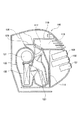
図5は、このような観点からなされたインストルメントパネルを示し、特開2002−187459号公報に開示されている。 FIG. 5 shows an instrument panel made from such a viewpoint, and is disclosed in Japanese Patent Application Laid-Open No. 2002-187459.
図5に示すように、インストルメントパネル100における車室側には、オーディオ101,102やエアコンコントローラ103が取り付けられている。このインストルメントパネル100の裏側には、フレーム構造体からなるクロスカービーム110が取り付けられると共に、空調ユニット120が配置されている。
As shown in FIG. 5,
空調ユニット120は、ブロア121、エバポレータ122、ヒータコア123等の構成部品を内部に備えており、クロスカービーム110の下側に配置されている。なお、空調ユニット120の上部には、デフ吹出用開口125が形成されており、このデフ吹出用開口125にデフダクト130が接続されている。
The
クロスカービーム110は、車室を横切る方向(紙面貫通方向)に延びており、その両端部が車体(図示省略)に固定される。また、長さ方向中央部分には脚部111が下方向に延びており、脚部111が車体に固定されるようになっている。空調ユニット120は、脚部111上に支持されることにより、クロスカービーム110に取り付けられている。さらに、クロスカービーム110は中空状の空気案内通路115を備えており、この空気案内通路115のベント吹出用開口117が空調ユニット120の吹出口と連通している。すなわち、クロスカービーム110は空調ユニット120からの空調風の通路となるものであり、空気案内通路115がダクトと接続されることにより、車室の空調を行うようになっている。
図5に示す構造では、クロスカービーム110に中空状の空気案内通路115が形成されているため、クロスカービーム110としての剛性が低下し、所定の剛性が得られない問題を有している。これに対し、クロスカービーム110に剛性を付与するためには、空気案内通路115を小さくする必要があるが、この場合には、空気案内通路115の送風抵抗が低下するため、空調ユニット120からの空調風を車室に十分に供給できないものとなる。
In the structure shown in FIG. 5, since the hollow
本発明は、このような従来の問題点を考慮してなされたものであり、空調ユニットからの空調風をクロスカービームを介して送風する構造とした場合であっても、クロスカービームの剛性を十分に確保することができると共に、空調風の送風抵抗を低下させることのない車両用空調ユニットの取付構造を提供することを目的とする。 The present invention has been made in consideration of such conventional problems, and the rigidity of the cross car beam is obtained even when the air conditioned air from the air conditioning unit is blown through the cross car beam. It is an object of the present invention to provide a mounting structure for a vehicle air-conditioning unit that can sufficiently secure the air-conditioning air and that does not reduce the blowing resistance of the conditioned air.
請求項1記載の発明は、インストルメントパネルの裏側で車室を横断するように配置されるクロスカービームによって空調ユニットが車体に固定される車両用空調ユニットの取付構造であって、空調ユニットに設けられた開口部と開口形状が一致する送風孔を有する送風用ブロックと、この送風用ブロックの対向する両側面から延設され、端部が車体に固定されるサイドビームとから前記クロスカービームが構成され、該送風用ブロックの入口側開口面に該空調ユニットの該開口部が連通されつつ、該送風用ブロックの出口側開口面にダクトが連通され、且つ空調ユニットが送風用ブロックを介してクロスカービームに固定されることを特徴とする。 The invention according to claim 1 is a mounting structure of a vehicle air conditioning unit in which the air conditioning unit is fixed to the vehicle body by a cross car beam disposed so as to cross the passenger compartment on the back side of the instrument panel. The crosscar beam from a blower block having a blower hole whose opening shape coincides with the provided opening, and a side beam extending from opposite side surfaces of the blower block and having an end fixed to the vehicle body The duct is communicated with the outlet side opening surface of the blower block while the opening portion of the air conditioning unit is communicated with the inlet side opening surface of the blower block, and the air conditioning unit passes through the blower block. It is fixed to the cross car beam.
請求項2記載の発明は、請求項1記載の車両用空調ユニットの取付構造であって、前記送風用ブロックとサイドビームとが別部材で構成されると共に、送風用ブロックとサイドビームとが締結部材によって組み付け可能となっていることを特徴とする。
The invention according to
請求項3記載の発明は、請求項1または2記載の車両用空調ユニットの取付構造であって、前記送風用ブロックと空調ユニットとに相互に係合する係合手段が設けられており、当該係合手段の係合状態で送風用ブロックと空調ユニットとが締結ネジによって締結されることを特徴とする。
Invention of
請求項4記載の発明は、請求項1〜3のいずれか1項に記載の車両用空調ユニットの取付構造であって、前記送風用ブロックの外形が空調ユニットの凹凸形状と嵌合する凹凸形状となっていることを特徴とする。
Invention of
請求項1記載の発明によれば、送風孔を有した送風用ブロックがクロスカービームの構成部材となっており、この送風用ブロックに空調ユニットが取り付けられると共に、送風用ブロックの送風孔が車室への送風を行うダクトと連通状に接続されるため、空調ユニットの空調風が送風孔を介してダクトに供給され、車室の空調を行うことができる。 According to the first aspect of the present invention, the blower block having the blower holes is a component of the cross car beam, the air conditioning unit is attached to the blower block, and the blower hole of the blower block is the vehicle. Since it is connected in communication with the duct that blows air to the compartment, the conditioned air of the air conditioning unit is supplied to the duct via the air vent, and the passenger compartment can be air-conditioned.
このような請求項1記載の発明では、送風用ブロックに形成した送風孔が空調風の通路となるものであり、クロスカービームの全体に空調風の通路を形成する必要がない。このため、クロスカービームの剛性を確保することができる。また、送風孔を大きくしても、クロスカービーム全体の剛性に影響することがない。これにより、空調ユニットからの空調風の送風抵抗を低下させることなく、ダクトに導くことができる。 In the invention according to the first aspect, the air blowing holes formed in the air blowing block serve as a passage for the conditioned air, and it is not necessary to form the air conditioned air passage in the entire cross car beam. For this reason, the rigidity of the cross car beam can be ensured. Moreover, even if the air blowing hole is enlarged, the rigidity of the entire cross car beam is not affected. Thereby, it can guide to a duct, without reducing the ventilation resistance of the conditioned air from an air-conditioning unit.
請求項2記載の発明によれば、請求項1記載の発明の効果に加えて、送風用ブロックが別体となっており、クロスカービームのサイドビームと組み付けられることによりクロスカービームを構成するため、クロスカービームを車種に合わせて変更することができ、汎用性のあるものとすることができる。
According to the invention described in
また、クロスカービーム及び空調ユニットの分解が容易となり、修理やメンテナンスの作業性が向上する。さらに、サイドビームとして、パイプ材を使用することができるため、コストを低減することが可能となる。 In addition, the disassembly of the cross car beam and the air conditioning unit is facilitated, and the workability of repair and maintenance is improved. Furthermore, since a pipe material can be used as the side beam, the cost can be reduced.
請求項3記載の発明によれば、請求項1及び2記載の発明の効果に加え、送風用ブロックと空調ユニットとに設けた係合手段を係合させることにより、クロスカービームに対する空調ユニットの位置決めを簡単且つ正確に行うことができる。このため、クロスカービームと空調ユニットとの組み付け作業性が向上する。 According to the third aspect of the present invention, in addition to the effects of the first and second aspects of the invention, the engagement means provided on the blower block and the air conditioning unit are engaged, whereby the air conditioning unit with respect to the cross car beam is engaged. Positioning can be performed easily and accurately. For this reason, the assembly workability of the cross car beam and the air conditioning unit is improved.
請求項4記載の発明によれば、請求項1〜3記載の発明の効果に加えて、送風用ブロックの凹凸形状と空調ユニットの凹凸形状とを嵌合させることにより、クロスカービームに対する空調ユニットの組み付けを行うことができるため、これらの組み付け作業性が向上する。 According to the fourth aspect of the present invention, in addition to the effects of the first to third aspects, the air conditioning unit for the cross car beam is formed by fitting the uneven shape of the air blowing block and the uneven shape of the air conditioning unit. Therefore, the assembling workability is improved.
以下、本発明を図示する実施形態により、具体的に説明する。なお、各実施形態において、同一の部材には同一の符号を付して対応させてある。 Hereinafter, the present invention will be described in detail with reference to the illustrated embodiments. In each embodiment, the same member is assigned the same reference numeral.
(第1実施形態)
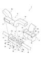
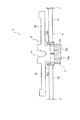
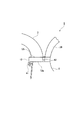
図1〜図4は、本発明の第1実施形態を示し、図1は分解斜視図、図2は組み付け状態の正面図、図3は組み付け状態の側面図である。
(First embodiment)
1 to 4 show a first embodiment of the present invention, FIG. 1 is an exploded perspective view, FIG. 2 is a front view in an assembled state, and FIG. 3 is a side view in the assembled state.
この実施形態の車両用空調ユニットの取付構造1は、クロスカービーム4と、クロスカービーム4に組み付けられる空調ユニット2とを備えている。これらのクロスカービーム4及び空調ユニット2は、車室前方側に設けられるインストルメントパネル(図示省略)の裏側に配置されるものである。
The vehicle air conditioning unit mounting structure 1 of this embodiment includes a
クロスカービーム4は、インストルメントパネルの裏側で車体の幅方向に延びており、その長さ方向における両端部に設けた取付ブラケット11(図2参照)が車体にネジ止め等により固定される。クロスカービーム4は、長さ方向の略中央部分に位置する送風用ブロック12と、送風用ブロック12の長さ方向の両端部の側面から車幅方向に沿って延びる一対のサイドビーム13,14とによって構成されている。サイドビーム13,14は、送風用ブロック12と別部材で構成されたもので、パイプ材が使用されることによりクロスカービーム4に所定の剛性を付与するようになっている。上述した取付ブラケット11は、それぞれのサイドビーム13,14の先端部分に一体的に設けられるものである。
The
送風用ブロック12は、平面から見て略矩形状に形成されており、長さ方向の両端部には、サイドビーム13,14が連結されるサイドブラケット部12a,12bが立ち上がり状に形成されている。これらのサイドブラケット部12a,12bとの間には、略矩形状のメインブロック部12cが一体的に形成されている。
The
メインブロック部12cは、後述する空調ユニット2を取り付けるためのものであり、クロスカービーム4の略中央部分に送風用ブロック12が位置することにより、空調ユニット2はクロスカービーム4の略中央部分に取り付けられるようになっている。メインブロック部12cには、3つの送風孔15,16,17が上下方向(厚さ方向)に貫通するように形成されている。3つの送風孔15,16,17は、個々独立するように区画されて形成されるものである。
The
これらの送風孔15,16,17は、空調ユニット2からの空調風の通路となるものであり、送風用ブロック12の入口側開口面12gに後述する空調ユニット2の開口部25,26,27が連通されつつ、送風用ブロック12の出口側開口面12hに後述するベントダクト3が連通されて、空調ユニット2が送風用ブロック12を介してクロスカービーム4に固定される。
These
空調ユニット2は、図示を省略したブロア、エバポレータ、ヒータコア等の構成部品を内部に備えている。また、その上端部には、センタ開口部25とサイド開口部26,27が形成されている。センタ開口部25は、送風用ブロック12における送風孔15に対応し、サイド開口部26,27は送風用ブロック12における左右の送風孔16,17に対応している。このため、送風用ブロック12における送風孔15,16,17は、対応した空調ユニット2の開口部25,26,27と略同形状及び略同サイズとなるように形成されるものである。さらに、空調ユニット2からは、フロントウインドへの曇止めを行うためのデフ通路29が上方に延びている。
The
空調ユニット2は、送風用ブロック12の真下に位置するように送風用ブロック12に取り付けられる。空調ユニット2の送風用ブロック12への取り付けは、締結ネジ41によって行われるものであり、送風用ブロック12には締結ネジ41が貫通する孔部12dが形成され、空調ユニット2の外側面における対応部位には、締結ネジ41が螺合するネジ孔2dが形成されている。この場合、送風用ブロック12の孔部12dは肉薄となって下方に垂下するストッパ部12fに形成されるものである。ストッパ部12fは、空調ユニット2の組み付け時に空調ユニット2の上部側面が当接するものである。
The
送風用ブロック12及び空調ユニット2には、相互に係合する係合手段が設けられている。この実施形態において、係合手段は空調ユニット2に設けられた係合ピン42と、係合ピン42と対応するように送風用ブロック12に係合された係合孔43とによって構成されている。この場合、係合ピン42は、空調ユニット2から上方に延びるデフ通路29の側面に突出状に形成され、係合孔43は送風用ブロック12における中央の送風孔15形成部位の背面に形成されている。このような係合ピン42及び係合孔43が相互に係合することにより、クロスカービーム4に対する空調ユニット2の位置決めを簡単且つ確実に行うことができる。
The blowing
さらに、この実施形態において、送風用ブロック12の外形は、空調ユニット2の凹凸形状と嵌合する凹凸形状に形成されるものであり、空調ユニット2がデフ通路29を備えていることから、送風用ブロック12の背面にはデフ通路29に嵌合する嵌合凹部44が形成されている。デフ通路29と嵌合凹部44とが嵌合することによりクロスカービーム4に対する空調ユニット2の位置決めを強固に行うことができ、組み付け作業性が向上する。
Furthermore, in this embodiment, the outer shape of the
ベントダクト3は、空調ユニット2からの空調風を車室内に送り込むダクトを構成するものであり、送風用ブロック12上に被せられた状態で同ブロック12に取り付けられる。ベントダクト3は車室側のセンタベント(図示省略)に連結されるセンタダクト31と、センタダクト31の両側に設けられたサイドダクト32,33とを有している。サイドダクト32,33は車室側のサイドベント(図示省略)に連結されるものである。
The
ベントダクト3におけるセンタダクト31は、送風用ブロック12の中央の送風孔15に対応し、左右のサイドダクト32,33は送風用ブロック12の左右の送風孔16,17に対応する。センタダクト31及び左右のサイドダクト32,33は一体となっており、一体となった状態で送風用ブロック12のサイドブラケット部12a,12bの間に嵌め込まれて固定されるものである。
The
次に、この実施形態の組み付け手順を説明する。車体に固定されたクロスカービーム4の送風用ブロック12に対し、空調ユニット2を接近させて、その係合ピン42を送風用ブロック12の係合孔43に係合させる。これと同時に、空調ユニット2のデフ通路29を送風用ブロック12の嵌合凹部44に嵌合させる。係合ピン42と係合孔43との係合及びデフ通路29と嵌合凹部44との嵌合により、空調ユニット2は送風用ブロック12に良好に位置決めされた状態となり、そのセンタ開口部25が送風用ブロック12の中央の送風孔15と一致し、左右のサイド開口部26,27が送風用ブロック12の左右の送風孔16,17と一致する。なお、係合ピン42と係合孔43との組み合わせ及びデフ通路29と嵌合凹部44との組み合わせは、いずれか一方であれば良いものである。
Next, the assembly procedure of this embodiment will be described. The
空調ユニット2の送風用ブロック12への位置決めの後、締結ネジ41を送風用ブロック12から空調ユニット2に螺合させることにより、空調ユニット2が送風用ブロック12に組み付けられる。この組み付けの後、送風用ブロック12のサイドブラケット部12a,12bの間に、ベントダクト3を挿入して組み付ける。サイドブラケット部12a,12bの間への挿入により、ベントダクト3はそのセンタダクト31が送風用ブロック12の中央の送風孔15と一致し、左右のサイドダクト32,33が送風用ブロック12の左右の送風孔16,17と一致する。その後、ネジ等の適宜の手段によって、ベントダクト3を送風用ブロック12に固定する。
After positioning the
このような状態では、送風用ブロック12の各送風孔15,16,17が対応したダクト31,32,33と連通状に接続される。このため、空調ユニット2からの温調風を送風孔15,16,17を介して、対応したダクト31,32,33に供給することができ、車室内の必要箇所への空調を行うことができる。
In such a state, the air blowing holes 15, 16, and 17 of the
このような実施形態では、送風用ブロック12に形成した送風孔15,16,17が空調ユニット2からの空調風の通路となるため、クロスカービーム4の全体に空調風の通路を形成する必要がない。このため、クロスカービーム4の剛性を確保することができる。また、空調風の通路となる送風孔15,16,17を大きくしても、クロスカービーム4の剛性に影響しない。このため、送風孔15,16,17を空調ユニット2からの空調風の送風抵抗を低下させることのないように形成することができ、車室内の空調を円滑且つ効率良く行うことができる。
In such an embodiment, the ventilation holes 15, 16, and 17 formed in the
さらにこの実施形態では、係合ピン42と係合孔43との係合状態で、締結ネジ41を螺合させることにより、空調ユニット2を組み付けるため、空調ユニット2を高精度に組み付けることができると共に、組み付けの作業性が向上する。
Furthermore, in this embodiment, since the
(第2実施形態)
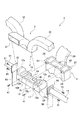
図4は、本発明の実施形態の分解斜視図を示す。この実施形態では、クロスカービーム4を構成する左右のサイドビーム13,14と、これらの間に設けられる送風用ブロック12とを別体とするものである。
(Second Embodiment)
FIG. 4 shows an exploded perspective view of an embodiment of the present invention. In this embodiment, the left and right side beams 13 and 14 constituting the
左右のサイドビーム13,14における送風用ブロック12側の端部には、取付板53,54が一体的に設けられており、それぞれの取付板53,54が送風用ブロック12の左右のサイドブラケット部12a,12bの外面と当接することにより、左右のサイドビーム13,14と送風用ブロック12との組み付けが行われるようになっている。左右のサイドビーム13,14と送風用ブロック12との組み付けは、締結部材としてのネジ51によって行われるものであり、取付板53,54をサイドブラケット部12a,12bに当接させた状態で、取付板53,54側からネジ51をサイドブラケット部12a,12bに螺合させることにより終了する。
Mounting
このような組み付けにより、クロスカービーム4が構成されるため、送風用ブロック12への空調ユニット2の組み付けを第1実施形態と同様にして行うことができる。従って、この実施形態においても、第1実施形態と同様な作用及び効果を有するものである。
Since the
この実施形態では、以上のように送風用ブロック12と左右のサイドビーム13,14とを別体とすることにより、クロスカービーム4の長さや形状あるいは構造を車種に合わせて変更することができるため、汎用性のあるものとすることができる。また、組み付けられたクロスカービーム4及び空調ユニット2の分解を簡単に行うことができるため、これらの修理やメンテナンスの作業性が向上する。さらに、左右のサイドビーム13,14として、安価なパイプ材を使用することができるため、コストを低減させることができる。
In this embodiment, the length, shape, or structure of the
以上に加えてこの実施形態では、左右のサイドビーム13,14の取付板53,54に脚部55,56が取り付けられている。脚部55,56は、その下端部が車体にネジ止め等により固定されるものであり、これにより、左右のサイドビーム13,14を強固に支持することができる。かかる脚部55,56は、送風用ブロック12を挟み込む取付板53,54に設けられるため、脚部55,56が送風用ブロック12に取り付けられる空調ユニット2を支持した構造となる。このため、空調ユニット2の支持力を強固にすることができ、空調ユニット2を安定して支持することができる。なお、以上の脚部55,56は、第1実施形態におけるサイドビーム13,14の送風用ブロック12側の端部に設けても良いものである。
In addition to the above, in this embodiment,
1 クロスカービーム
2 空調ユニット
3 ベントダクト
12 送風用ブロック
13,14 サイドビーム
15,16,17 送風孔
29 デフベント
41 締結ネジ
42 係合ピン
43 係合孔
44 嵌合凹部
51 ネジ
53,54 取付板
55,56 脚部
DESCRIPTION OF SYMBOLS 1
Claims (4)
空調ユニット(2)に設けられた開口部(25,26,27)と開口形状が一致する送風孔(15,16,17)を有する送風用ブロック(12)と、
この送風用ブロック(12)の対向する両側面から延設され、端部が車体に固定されるサイドビーム(13,14)とから前記クロスカービーム(4)が構成され、
該送風用ブロック(12)の入口側開口面(12g)に該空調ユニット(2)の該開口部(25,26,27)が連通されつつ、該送風用ブロック(12)の出口側開口面(12h)にダクト(3)が連通され、且つ空調ユニット(2)が送風用ブロック(12)を介してクロスカービーム(4)に固定されることを特徴とする車両用空調ユニットの取付構造。 A vehicle air conditioning unit mounting structure (1) in which the air conditioning unit (2) is fixed to the vehicle body by a cross car beam (4) arranged to cross the passenger compartment on the back side of the instrument panel,
An air blowing block (12) having air holes (15, 16, 17) whose opening shapes coincide with the openings (25, 26, 27) provided in the air conditioning unit (2);
The cross car beam (4) is composed of side beams (13, 14) extending from opposite side surfaces of the air blowing block (12) and having end portions fixed to the vehicle body,
The opening (25, 26, 27) of the air conditioning unit (2) communicates with the inlet-side opening (12g) of the blowing block (12), and the outlet-side opening of the blowing block (12). The vehicle air conditioning unit mounting structure is characterized in that the duct (3) communicates with (12h) and the air conditioning unit (2) is fixed to the cross car beam (4) via the blower block (12). .
前記送風用ブロック(12)とサイドビーム(13,14)とが別部材で構成されると共に、送風用ブロック(12)とサイドビーム(13,14)とが締結部材(51)によって組み付け可能となっていることを特徴とする車両用空調ユニットの取付構造。 The vehicle air conditioning unit mounting structure (1) according to claim 1,
The blower block (12) and the side beams (13, 14) are configured as separate members, and the blower block (12) and the side beams (13, 14) can be assembled by the fastening member (51). A structure for mounting an air conditioning unit for a vehicle.
前記送風用ブロック(12)と空調ユニット(2)とに相互に係合する係合手段(42,43)が設けられており、当該係合手段(42,43)の係合状態で送風用ブロック(12)と空調ユニット(2)とが締結ネジ(41)によって締結されることを特徴とする車両用空調ユニットの取付構造。 The vehicle air conditioning unit mounting structure (1) according to claim 1 or 2,
Engaging means (42, 43) are provided to engage the air blowing unit (12) and the air conditioning unit (2). The vehicle air conditioning unit mounting structure, wherein the block (12) and the air conditioning unit (2) are fastened by a fastening screw (41).
前記送風用ブロック(12)の外形が空調ユニット(2)の凹凸形状と嵌合する凹凸形状(44)となっていることを特徴とする車両用空調ユニットの取付構造。
The vehicle air conditioning unit mounting structure (1) according to any one of claims 1 to 3,
The vehicle air-conditioning unit mounting structure is characterized in that an outer shape of the air blowing block (12) is a concave-convex shape (44) fitted to the concave-convex shape of the air-conditioning unit (2).
Priority Applications (1)
| Application Number | Priority Date | Filing Date | Title |
|---|---|---|---|
| JP2004120636A JP2005297914A (en) | 2004-04-15 | 2004-04-15 | Mounting structure of air conditioning unit for vehicle |
Applications Claiming Priority (1)
| Application Number | Priority Date | Filing Date | Title |
|---|---|---|---|
| JP2004120636A JP2005297914A (en) | 2004-04-15 | 2004-04-15 | Mounting structure of air conditioning unit for vehicle |
Publications (1)
| Publication Number | Publication Date |
|---|---|
| JP2005297914A true JP2005297914A (en) | 2005-10-27 |
Family
ID=35329967
Family Applications (1)
| Application Number | Title | Priority Date | Filing Date |
|---|---|---|---|
| JP2004120636A Pending JP2005297914A (en) | 2004-04-15 | 2004-04-15 | Mounting structure of air conditioning unit for vehicle |
Country Status (1)
| Country | Link |
|---|---|
| JP (1) | JP2005297914A (en) |
Cited By (2)
| Publication number | Priority date | Publication date | Assignee | Title |
|---|---|---|---|---|
| JP2019025933A (en) * | 2017-07-25 | 2019-02-21 | ダイキョーニシカワ株式会社 | Mounting structure of air conditioning duct for vehicle |
| CN110228345A (en) * | 2018-06-08 | 2019-09-13 | 蔚来汽车有限公司 | Vehicle blows foot air channel structure and the vehicle including it |
-
2004
- 2004-04-15 JP JP2004120636A patent/JP2005297914A/en active Pending
Cited By (2)
| Publication number | Priority date | Publication date | Assignee | Title |
|---|---|---|---|---|
| JP2019025933A (en) * | 2017-07-25 | 2019-02-21 | ダイキョーニシカワ株式会社 | Mounting structure of air conditioning duct for vehicle |
| CN110228345A (en) * | 2018-06-08 | 2019-09-13 | 蔚来汽车有限公司 | Vehicle blows foot air channel structure and the vehicle including it |
Similar Documents
| Publication | Publication Date | Title |
|---|---|---|
| JP2012144173A (en) | Air conditioner for vehicle | |
| JP2004203244A (en) | Defroster nozzle | |
| JP4684040B2 (en) | Panel device | |
| JP2005297914A (en) | Mounting structure of air conditioning unit for vehicle | |
| JP4192376B2 (en) | Cockpit module assembly for vehicle | |
| JP2018016233A (en) | Air conditioner for vehicles | |
| JP2009208590A (en) | Steering member mounting structure | |
| JP2003136942A (en) | Vehicle mounting structure of air conditioner and vehicle mounting method | |
| JP4943245B2 (en) | Ceiling unit for railway vehicles | |
| JP5270972B2 (en) | Vehicle wind direction adjusting device | |
| JP2016222048A (en) | Vehicular air-conditioning blowout port part structure | |
| JP4591805B2 (en) | Case extension member | |
| JP2007076481A (en) | Register structure of vehicle | |
| JP4178701B2 (en) | Cockpit module assembly for vehicle | |
| JP2001001946A (en) | Mounting structure of steering member | |
| JP4534198B2 (en) | Defroster duct mounting structure | |
| CN208085821U (en) | The dashboard cross member and automobile of integration assembly | |
| JP2548727Y2 (en) | Louver mounting structure for air conditioner | |
| JP2002178791A (en) | Temporary fixing structure of cockpit module assembly | |
| JP3710004B2 (en) | Duct structure for vehicle air conditioning | |
| JP5687081B2 (en) | Air conditioner for vehicles | |
| JP5995170B2 (en) | Air conditioning unit for vehicles | |
| JP3725055B2 (en) | Installation structure of vehicle outlet panel | |
| JP2011025728A (en) | Vehicular air-conditioner | |
| JP2024090407A (en) | Defroster diffuser structure |