本発明は、建設現場などで使用される枠組足場を組立・分解するときに、作業者の転落事故防止のため、枠組足場の最上段に設ける先行手摺に関する。
The present invention relates to a handrail provided at the uppermost stage of a frame scaffold in order to prevent an operator from falling down when assembling / disassembling a frame scaffold used at a construction site or the like.
建設現場などで使用される枠組足場は、門形をした2本の建枠をXの字状のブレースで連結し、建枠頂部の横桟パイプの間に布板を載置したものをユニットとし、このユニットを建設現場の幅と高さに応じて左右・上下に連結して枠組足場を構成する。
The frame scaffold used at construction sites is a unit in which two gate-shaped building frames are connected by X-shaped braces and a cloth plate is placed between the horizontal beam pipes at the top of the building frame. This unit is connected to the left and right and up and down according to the width and height of the construction site to form a framework scaffold.
したがって、最上段以外の布板に立って作業するときは建枠を連結しているブレースが安全柵の役目を果たすが、最上段の布板に立って作業するときの転落事故防止のため、先行手摺を設けている。
Therefore, the brace that connects the building frame serves as a safety fence when working on a fabric board other than the top, but to prevent falling accidents when working while standing on the top fabric board, A leading handrail is provided.
このような手摺として、実用新案登録第3095790号公報には、左右一対の垂直材と、垂直材の上端をつなぐ水平材と、水平材の下方に位置し左右の垂直材をつなぐ下部支持枠とで手摺枠を構成し、手摺枠の左右下端部に一対のクランプを設け、一対のクランプで枠組足場の建枠の建地パイプに取り付ける先行手摺において、手摺枠の左右の一方のみにクランプの上方に位置する掛止金物を設け、掛止金物を枠組足場の建枠頂部の横桟パイプに掛止し、掛止金物の無い側のクランプから建地パイプに取り付けるものを、本発明者が提案した。
As such a handrail, utility model registration No. 3095790 discloses a pair of left and right vertical members, a horizontal member that connects the upper ends of the vertical members, and a lower support frame that is located below the horizontal member and connects the left and right vertical members. The handrail frame is configured with a pair of clamps at the left and right lower ends of the handrail frame, and the pair of clamps is attached to the building pipe of the frame of the frame scaffolding. The present inventor proposes that a latch is located on the side of the frame scaffolding and is attached to the building pipe from the clamp on the side without the latch. did.
この手摺は、全ての枠組足場ユニットに取り付けるのではなく、ブレースの設置されていない最上段にのみ取り付けるものである。手摺りを上段に盛り替える(付け替える)には、掛止金物を枠組足場の建枠頂部の横桟パイプに掛止し、掛止金物の無い側のクランプから建地パイプに取り付けるものであり、不要に先行手摺を高く手で持ち上げる必要が無く、一人の作業者がクランプを手で持ち上げ固定できるから、人手を多く必要としないものである。
This handrail is not attached to all frame scaffold units, but only to the uppermost stage where no braces are installed. To rearrange (replace) the handrail to the upper level, hook the latch on the horizontal beam pipe at the top of the building frame of the frame scaffolding, and attach it to the building pipe from the clamp on the side without the latch. There is no need to lift the handrail unnecessarily high, and one operator can lift and fix the clamp by hand, so that a large number of hands are not required.
また、特開2002−206336号公報には、足場用建枠の対向する両縦材間に配置される手摺本体と、手摺本体の両側端部に取り付けられ、足場用建枠の横材に対し係脱自在な係止フックと、手摺本体の両側端部に設けられ、手摺本体を足場用建枠の縦材に沿って案内するガイド手段とによるものが示されている。
Japanese Patent Laid-Open No. 2002-206336 discloses a handrail main body disposed between opposing vertical members of a scaffold building frame, and attached to both side ends of the handrail main body, to the transverse member of the scaffold building frame. A lock hook that can be freely engaged and disengaged and guide means that is provided at both end portions of the handrail main body and guides the handrail main body along the vertical members of the scaffolding frame are shown.
このガイド手段は、手摺本体の側端部の上下複数箇所にブラケットを突設し、各ブラケットに、足場用建枠の縦材を内外両側から挟持するような内外一対のガイド板を取り付けている。また、手摺本体は幅方向に伸縮自在に構成されている。
This guide means has a plurality of brackets projecting from the top and bottom of the side end portion of the handrail body, and a pair of inner and outer guide plates are attached to each bracket so as to sandwich the vertical members of the scaffolding frame from the inner and outer sides. . The handrail body is configured to be extendable and contractible in the width direction.
この手摺は、手摺本体を足場用建枠の建地パイプに沿って案内するガイド手段により上下させ、手摺を取り外すことなく上段に盛り替えるものである。そして、手摺本体を幅方向に伸縮するのは、手摺本体を足場用建枠の建地パイプに挿入する最初と、取り外す最後だけである。
In this handrail, the handrail body is moved up and down by guide means that guides the building frame along the building pipe of the scaffolding frame, and the handrail is rearranged to the upper stage without removing the handrail. And the handrail main body is expanded and contracted in the width direction only at the beginning of inserting the handrail main body into the building pipe of the scaffolding frame and at the last removing.
また、特許第2951274号公報には、足場板の片側または両側に設けられ、対向する2つの建枠の水平杆に架け渡される手摺り枠において、建枠間に両端に設けたつかみ金具によって掛け渡される下杆と、下杆の少なくとも一端側の長さを微調整するために下杆と摺動自在に設けられるつかみ金具とによるコーナー手摺り枠が示されている。
In Japanese Patent No. 2951274, in a handrail frame provided on one side or both sides of a scaffolding plate and spanning the horizontal fence of two opposing building frames, it is hung by gripping metal fittings provided at both ends between the building frames. A corner handrail frame is shown that includes a lower arm that is handed over and a grip that is slidably provided in order to finely adjust the length of at least one end of the lower arm.
このコーナー手摺り枠は、枠組足場の足場板等の部材の長さや幅の寸法が異なっていても、簡単にそのスケールに対応できるものである。
実用新案登録第3095790号公報
特開2002−206336号公報
特許第2951274号公報
This corner railing frame can be easily adapted to the scale even if the length and width dimensions of members such as scaffolding plates of the frame scaffolding are different.
Utility Model Registration No. 3095790 JP 2002-206336 A Japanese Patent No. 2951274
上記の実用新案登録第3095790号公報に示される従来技術においては、手摺りを上段に盛り替えるには、1段目と2段目とに二名の作業者を必要とするものである。
In the prior art disclosed in the above-mentioned utility model registration No. 3095790, two workers are required for the first stage and the second stage in order to rearrange the handrail to the upper stage.
また、特開2002−206336号公報に示される従来技術においては、手摺本体を幅方向に伸縮するのは、手摺本体を足場用建枠の建地パイプに挿入するためであり、足場間隔の異なるものに対応することはできない。また、構造が複雑となる。
Moreover, in the prior art shown by Unexamined-Japanese-Patent No. 2002-206336, the handrail main body is expanded-contracted in the width direction in order to insert a handrail main body into the building pipe of a building frame for scaffolds, and a scaffold space | interval differs. Can't deal with things. In addition, the structure becomes complicated.
また、特許第2951274号公報に示される従来技術においては、足場間隔の異なるものに対応することはできるが、先行手摺として上段に盛り替えることはできない。
Moreover, in the prior art shown by patent 2951274, although it can respond | correspond to the thing from which a scaffold space | interval differs, it cannot be rearranged to an upper stage as a preceding handrail.
そこで本発明では、伸縮幅を大きくして足場間隔の異なるものに対応することができ、一人作業で上段に盛り替えることができ、構造が簡単で軽量化ができ、取り付け取り外し時に不要に手摺が落下することなく、妻側にも取り付けることができる、枠組足場のスライド式先行手摺を提供する事を目的とする。
Therefore, in the present invention, the expansion and contraction width can be increased to cope with different scaffold intervals, the work can be rearranged to the upper stage by one person work, the structure is simple and light weight, and the handrail is unnecessary when attaching and detaching. The object is to provide a sliding scaffolding handrail for the frame scaffolding that can be attached to the wife side without falling.
請求項1の発明による枠組足場のスライド式先行手摺は、左右一対の垂直材11,41と、垂直材11,41の上端をつなぐ上水平材12,42と、垂直材11,41の中間部をつなぐ中間水平材15,45とで手摺枠10,40を構成し、上水平材12,42と中間水平材15,45はその中間部で二分割され、二分割された上水平材12,42の一方を太上水平材13,43とし、もう一方を細上水平材14,44とし、細上水平材14,44は太上水平材13,43にスライド自在にはまり込み、二分割された中間水平材15,45の一方を太中間水平材16,46とし、もう一方を細中間水平材17,47とし、細中間水平材17,47は太中間水平材16,46にスライド自在にはまり込み、太中間水平材16,46の細中間水平材17,47側の下方にロックボルト19,49を設け、ロックボルト19,49は布板3の上方に位置し、ロックボルト19,49を締め付けることにより細中間水平材17,47と太中間水平材16,46のスライドは固定されるものである。
The sliding scaffolding handrail of the frame scaffold according to the invention of claim 1 includes a pair of left and right vertical members 11, 41, upper horizontal members 12, 42 connecting the upper ends of the vertical members 11, 41, and an intermediate portion of the vertical members 11, 41. The intermediate horizontal members 15 and 45 connecting the rails constitute the handrail frames 10 and 40, and the upper horizontal members 12 and 42 and the intermediate horizontal members 15 and 45 are divided into two at the middle portion thereof, and the upper horizontal members 12 and One of the 42 is a thick upper horizontal member 13, 43 and the other is a thin upper horizontal member 14, 44. The thin upper horizontal member 14, 44 is slidably fitted into the thick horizontal member 13, 43 and divided into two. One of the intermediate horizontal members 15, 45 is a thick intermediate horizontal member 16, 46, and the other is a thin intermediate horizontal member 17, 47. The thin intermediate horizontal members 17, 47 are slidable on the thick intermediate horizontal members 16, 46. The lock bolts 19 and 49 are provided below the thin intermediate horizontal members 17 and 47 of the thick intermediate horizontal members 16 and 46. The lock bolts 19 and 49 are located above the cloth plate 3, and the lock bolts 19 and 49 are provided. The Fine slide of the intermediate horizontal members 17, 47 and thickness intermediate horizontal member 16, 46 by attaching eye is intended to be fixed.
請求項2の発明による枠組足場のスライド式先行手摺は、垂直材11の下端から一対の下側の押さえ金物24を設け、垂直材11の下端より所定距離上方から一方の垂直材11にフック金物21をもう一方の垂直材11に上側の押さえ金物25を設け、フック金物21には枠組足場1建枠2の建地パイプ2aの外側にはまるCの字状のフック切欠き22を設け、押さえ金物24,25には枠組足場1建枠2の建地パイプ2aの外側にはまるUの字状の押さえ切欠き26を設け、押さえ切欠き26の開口部は各々外側に向け、フック金物21と上側の押さえ金物25は枠組足場1の建枠2頂部の横桟パイプ2bより上方に位置させるものである。
The sliding scaffolding handrail of the frame scaffold according to the invention of claim 2 is provided with a pair of lower holding metal parts 24 from the lower end of the vertical member 11, and hook metal fittings on one vertical member 11 from a predetermined distance above the lower end of the vertical member 11. 21 is provided with the upper holding metal 25 on the other vertical member 11, and the hook metal 21 is provided with a C-shaped hook notch 22 that fits outside the building pipe 2a of the frame scaffold 1 building frame 2. The metal fittings 24 and 25 are provided with U-shaped presser cutouts 26 that are fitted outside the building pipe 2a of the frame scaffold 1 and the frame 2, and the openings of the presser cutouts 26 are directed outward, The upper holding metal 25 is positioned above the crosspiece pipe 2b at the top of the building frame 2 of the frame scaffold 1.
請求項3の発明による枠組足場のスライド式先行手摺は、フック金物21におけるフック切欠き22の開口部23を枠組足場1の外方に向けたものである。
The slide type advance handrail of the frame scaffold according to the invention of claim 3 is such that the opening 23 of the hook notch 22 in the hook hardware 21 faces the outside of the frame scaffold 1.
請求項4の発明による枠組足場のスライド式先行手摺は、垂直材41の下端から一対の下側の押さえ金物51を設け、垂直材41の下端より所定距離上方から一対の上側の押さえ金物52を設け、押さえ金物51,52には枠組足場1建枠2の建地パイプ2aの外側にはまるUの字状の押さえ切欠き53を設け、押さえ切欠き53の開口部は各々外側に向け、上側の押さえ金物52は枠組足場1の建枠2頂部の横桟パイプ2bより上方に位置させ、押さえ金物51,52の押さえ切欠き53を垂直材41より内方に位置させたものである。
According to the fourth aspect of the present invention, the frame type scaffolding slide type handrail is provided with a pair of lower pressers 51 from the lower end of the vertical member 41, and a pair of upper pressers 52 from above the lower end of the vertical member 41 by a predetermined distance. Provided in the presser fittings 51, 52 are U-shaped presser cutouts 53 that fit on the outside of the building pipe 2a of the frame scaffolding 1 building frame 2, and the opening portions of the presser cutouts 53 are directed outwardly and upward. The presser metal fitting 52 is positioned above the crosspiece pipe 2b at the top of the building frame 2 of the frame scaffold 1 and the presser cutouts 53 of the presser metal fixtures 51 and 52 are positioned inward from the vertical member 41.
請求項1の発明によれば、上水平材12,42と中間水平材15,45はその中間部で二分割され、二分割された上水平材12,42の一方を太上水平材13,43とし、もう一方を細上水平材14,44とし、細上水平材14,44は太上水平材13,43にスライド自在にはまり込み、二分割された中間水平材15,45の一方を太中間水平材16,46とし、もう一方を細中間水平材17,47とし、細中間水平材17,47は太中間水平材16,46にスライド自在にはまり込むため、細上水平材14,44は太上水平材13,43にほぼ完全にはまり込み、細中間水平材17,47は太中間水平材16,46にほぼ完全にはまり込み、伸縮幅が大きいから、足場間隔の異なるものにも対応できる。また、縮めて持ち運びできるので、取り扱いが容易となり、収納場所が少なく運搬費も安くなる。
According to the invention of claim 1, the upper horizontal members 12, 42 and the intermediate horizontal members 15, 45 are divided into two at the middle portion, and one of the two divided upper horizontal members 12, 42 is replaced by a thick upper horizontal member 13, 43, and the other is the fine horizontal members 14, 44. The fine horizontal members 14, 44 are slidably fitted into the thick horizontal members 13, 43, and one of the divided intermediate horizontal members 15, 45 is The thick intermediate horizontal members 16 and 46 are used, the other is the thin intermediate horizontal members 17 and 47, and the thin intermediate horizontal members 17 and 47 are slidably fitted into the thick intermediate horizontal members 16 and 46. 44 fits almost completely into the upper horizontal members 13 and 43, and the thin intermediate horizontal members 17 and 47 fit almost completely into the thick intermediate horizontal members 16 and 46. Can also respond. In addition, since it can be carried in a reduced size, it can be handled easily, has a small storage space and is low in transportation cost.
また、太中間水平材16,46の細中間水平材17,47側の下方にロックボルト19,49を設け、ロックボルト19,49を締め付けることにより細中間水平材17,47と太中間水平材16,46のスライドは固定されるため、片手で一方の垂直材11,41を持ち、もう一方の手でロックボルト19,49を締め付けることができるから、一人で手摺枠10,40を枠組足場1に取り付けることができる。また、ロックボルト19,49は布板3の上方に位置するため、手摺枠10,40が取り付けられている段からロックボルト19,49を緩めることができるから、一人で手摺枠10,40を枠組足場1から外すことができる。
Further, by providing lock bolts 19 and 49 below the thick intermediate horizontal members 16 and 46 on the thin intermediate horizontal members 17 and 47 side and tightening the lock bolts 19 and 49, the thin intermediate horizontal members 17 and 47 and the thick intermediate horizontal member Since the slides of 16 and 46 are fixed, one hand can hold the vertical members 11 and 41 and the other hand can tighten the lock bolts 19 and 49. 1 can be attached. Further, since the lock bolts 19 and 49 are positioned above the cloth plate 3, the lock bolts 19 and 49 can be loosened from the stage where the handrail frames 10 and 40 are attached. It can be removed from the framework scaffold 1.
請求項2の発明によれば、垂直材11の下端より所定距離上方から一方の垂直材11にフック金物21をもう一方の垂直材11に上側の押さえ金物25を設け、フック金物21には枠組足場1建枠2の建地パイプ2aの外側にはまるCの字状のフック切欠き22を設け、フック金物21と上側の押さえ金物25は枠組足場1の建枠2頂部の横桟パイプ2bより上方に位置させるため、まずフック金物21を横桟パイプ2bより上方の建地パイプ2aに掛けてから手摺枠10をスライドさせることができるから、安全に一人で手摺枠10を枠組足場1に取り付けることができる。
According to the second aspect of the present invention, the hook metal 21 is provided on one vertical member 11 and the upper holding metal 25 is provided on the other vertical member 11 from above the lower end of the vertical member 11. A C-shaped hook notch 22 that fits outside the building pipe 2a of the scaffold 1 building frame 2 is provided, and the hook metal 21 and the upper holding metal 25 are from the horizontal beam pipe 2b at the top of the building frame 2 of the frame scaffold 1 Since the handrail frame 10 can be slid after the hook hardware 21 is first hung on the building pipe 2a above the crosspiece pipe 2b in order to be positioned above, the handrail frame 10 can be safely attached to the frame scaffold 1 alone. be able to.
また、垂直材11の下端から一対の下側の押さえ金物24を設け、垂直材11の下端より所定距離上方から一方の垂直材11にフック金物21をもう一方の垂直材11に上側の押さえ金物25を設け、フック金物21には枠組足場1建枠2の建地パイプ2aの外側にはまるCの字状のフック切欠き22を設け、押さえ金物24,25には枠組足場1建枠2の建地パイプ2aの外側にはまるUの字状の押さえ切欠き26を設け、押さえ切欠き26の開口部は各々外側に向け、フック金物21と上側の押さえ金物25は枠組足場1の建枠2頂部の横桟パイプ2bより上方に位置させるため、手摺枠10をスライドさせてロックボルト19で固定することにより、フック金物21と押さえ金物24,25で建地パイプ2aに固定され、手摺枠10が枠組足場1に確実に取り付けられ、構造が簡単で軽量化できる。
Also, a pair of lower presser fixtures 24 are provided from the lower end of the vertical member 11, and a hook fixture 21 is attached to one vertical member 11 from the lower end of the vertical member 11, and an upper presser fixture is provided to the other vertical member 11. 25 is provided, and the hook hardware 21 is provided with a C-shaped hook notch 22 that fits outside the building pipe 2a of the frame scaffolding 1 building frame 2, and the holding brackets 24 and 25 are provided with the frame scaffolding 1 building frame 2 A U-shaped presser cutout 26 is provided on the outer side of the building pipe 2a. The opening of the presser cutout 26 is directed outward, and the hook metal 21 and the upper presser metal 25 are the building frame 2 of the frame scaffold 1 Since the handrail frame 10 is slid and fixed with the lock bolt 19 so as to be positioned above the top crosspiece pipe 2b, the handrail frame 10 is fixed to the building pipe 2a with the hook hardware 21 and the holding hardware 24, 25. Is securely attached to the frame scaffold 1, and the structure is simple and can be reduced in weight.
請求項3の発明によれば、フック金物21におけるフック切欠き22の開口部23を枠組足場1の外方に向けたから、手摺枠10を取り付けるときや取り外すときに、不用意に落下させることがない。
According to the invention of claim 3, since the opening 23 of the hook notch 22 in the hook hardware 21 is directed to the outside of the frame scaffold 1, it can be dropped carelessly when the handrail frame 10 is attached or removed. Absent.
請求項4の発明によれば、押さえ金物51,52には枠組足場1建枠2の建地パイプ2aの外側にはまるUの字状の押さえ切欠き53を設け、押さえ金物51,52の押さえ切欠き53を垂直材41より内方に位置させたため、垂直材41が建地パイプ2aの外方に位置するから、手摺枠40を枠組足場1の妻側にも取り付けることができる。
According to the invention of claim 4, the presser fittings 51, 52 are provided with U-shaped presser cutouts 53 that fit outside the building pipe 2 a of the frame scaffold 1 building frame 2. Since the notch 53 is positioned inward from the vertical member 41, the vertical member 41 is positioned outside the building pipe 2a, so that the handrail frame 40 can be attached to the wife side of the frame scaffold 1 as well.
また、垂直材41の下端から一対の下側の押さえ金物51を設け、垂直材41の下端より所定距離上方から一対の上側の押さえ金物52を設け、押さえ金物51,52には枠組足場1建枠2の建地パイプ2aの外側にはまるUの字状の押さえ切欠き53を設け、押さえ切欠き53の開口部は各々外側に向け、上側の押さえ金物52は枠組足場1の建枠2頂部の横桟パイプ2bより上方に位置させるため、手摺枠40をスライドさせてロックボルト49で固定することにより、押さえ金物51,52で建地パイプ2aに固定され、手摺枠40が枠組足場1に確実に取り付けられ、構造が簡単で軽量化できる。
In addition, a pair of lower pressers 51 are provided from the lower end of the vertical member 41, and a pair of upper pressers 52 are provided from above the lower end of the vertical member 41 by a predetermined distance. U-shaped presser cutouts 53 are provided on the outer side of the building pipe 2a of the frame 2, the openings of the presser cutouts 53 are directed outward, and the upper presser fitting 52 is the top of the building frame 2 of the frame scaffold 1 The handrail frame 40 is slid and fixed with the lock bolt 49 so that the handrail frame 40 is fixed to the building pipe 2a by the presser hardware 51 and 52 so that the handrail frame 40 is fixed to the frame scaffold 1 It is securely attached and the structure is simple and light.
伸縮幅を大きくして足場間隔の異なるものに対応することができるという目的を、上水平材12,42と中間水平材15,45はその中間部で二分割され、二分割された上水平材12,42の一方を太上水平材13,43とし、もう一方を細上水平材14,44とし、細上水平材14,44は太上水平材13,43にスライド自在にはまり込み、二分割された中間水平材15,45の一方を太中間水平材16,46とし、もう一方を細中間水平材17,47とし、細中間水平材17,47は太中間水平材16,46にスライド自在にはまり込むことにより実現した。
The upper horizontal members 12 and 42 and the intermediate horizontal members 15 and 45 are divided into two parts at the middle part for the purpose of increasing the expansion / contraction width to accommodate different scaffold intervals. One of 12 and 42 is a thick upper horizontal member 13 and 43, and the other is a thin upper horizontal member 14 and 44. The thin upper horizontal members 14 and 44 are slidably fitted into the thick upper horizontal members 13 and 43, and two One of the divided intermediate horizontal members 15, 45 is a thick intermediate horizontal member 16, 46, the other is a thin intermediate horizontal member 17, 47, and the fine intermediate horizontal members 17, 47 slide on the thick intermediate horizontal member 16, 46. Realized by freely fitting.
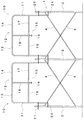
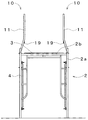
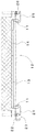
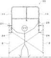
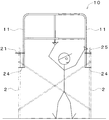
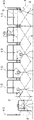
図1に示すのは枠組足場1に取り付けた先行手摺10であり、枠組足場1は複数の門形をした建枠2が平行に立設され、その建枠2をブレース4で連結し、その建枠2の頂部の間に布板3を載置して作業者の足場としたものである。
FIG. 1 shows a leading handrail 10 attached to a frame scaffold 1. The frame scaffold 1 has a plurality of gate-shaped building frames 2 erected in parallel, and the building frames 2 are connected by braces 4. A cloth plate 3 is placed between the tops of the building frame 2 to form a scaffold for the operator.
建枠2には、垂直方向に平行な一対の建地パイプ2aと、建地パイプ2aの頂部の間をつなぐ水平方向の横桟パイプ2bを設ける。建枠2の一対の建地パイプ2aの間隔は1219mmの物を示しているが、他に914mmのものや610mmのものなどが有る。この建地パイプ2aの間隔が、枠組足場1の妻側の間隔となる。建枠2の桁側に配置する間隔は1829mmの標準状態としたものを示しているが、ブレースの違いにより、他に1524mmのものや1219mmのものなどが有る。
The building frame 2 is provided with a pair of building pipes 2a parallel to the vertical direction and a horizontal crosspiece pipe 2b connecting between the tops of the building pipes 2a. The distance between the pair of building pipes 2a of the building frame 2 is 1219 mm, but there are 914 mm and 610 mm. The interval between the building pipes 2a is the interval on the wife side of the frame scaffold 1. Although the interval arranged on the girder side of the building frame 2 shows a standard state of 1829 mm, there are other types of 1524 mm and 1219 mm depending on the brace.
実施例1の先行手摺としての手摺枠10には、左右一対の垂直材11と、垂直材11の上端をつなぐ上水平材12と、垂直材11の中間部をつなぐ中間水平材15とを設ける。実施例では、垂直材11の長さを約140cm、標準状態の建枠2の間隔に取り付けた標準状態の左右一対の垂直材11の間隔を1,560mmとした。
The handrail frame 10 as the preceding handrail of the first embodiment is provided with a pair of left and right vertical members 11, an upper horizontal member 12 that connects the upper ends of the vertical members 11, and an intermediate horizontal member 15 that connects an intermediate portion of the vertical members 11. . In the embodiment, the length of the vertical member 11 is about 140 cm, and the distance between the pair of left and right vertical members 11 in the standard state attached to the interval between the standard building frames 2 is 1,560 mm.
垂直材11は、その側面視で中間部とその下半分の中間部の二箇所でへの字状に互いに反対方向に曲げられ、下部が建地パイプ2aに取り付けられた垂直材11の上部がブレース4と干渉しない内側となるようにしている。
The vertical member 11 is bent in two opposite directions in the middle part and the middle part of the lower half in the side view, and the upper part of the vertical member 11 attached to the building pipe 2a is the lower part. It is designed to be inside so as not to interfere with the brace 4.
上水平材12はその中間部で二分割され、二分割された上水平材12の一方を太上水平材13とし、もう一方を細上水平材14とする。以下便宜上、太上水平材13側を左、細上水平材14側を右として説明する。
The upper horizontal member 12 is divided into two at the intermediate portion, and one of the two divided upper horizontal members 12 is a thick upper horizontal member 13 and the other is a thin upper horizontal member 14. Hereinafter, for the sake of convenience, the description will be made assuming that the thick horizontal member 13 side is on the left and the fine upper horizontal member 14 side is on the right.
左側の垂直材11と太上水平材13は、丸管を90度内側に曲げて一体に構成される。実施例では、垂直材11と太上水平材13は、外径が35mm、肉厚が1.5mmの丸鋼管とし、左側の垂直材11の中心から太上水平材13の先端までの長さを930mmとした。
The left vertical member 11 and the thick upper horizontal member 13 are integrally formed by bending a round tube inward by 90 degrees. In the embodiment, the vertical member 11 and the thick horizontal member 13 are round steel pipes having an outer diameter of 35 mm and a wall thickness of 1.5 mm, and the length from the center of the left vertical member 11 to the tip of the thick upper member 13. Was 930 mm.
右側の垂直材11の上部を90度内側に曲げ、その先に細上水平材14を溶着する。細上水平材14の外径は太上水平材13の内径より小さくし、細上水平材14は太上水平材13にスライド自在にはまり込む。実施例では、細上水平材14は外径が30mm、肉厚が1.5mmの丸鋼管とし、右側の垂直材11の中心から細上水平材14の先端までの長さを930mmとした。つまり、標準状態では細上水平材14は太上水平材13に300mmはまり込む。
The upper part of the right vertical member 11 is bent inward by 90 degrees, and a thin upper horizontal member 14 is welded to the end. The outer diameter of the fine upper horizontal member 14 is smaller than the inner diameter of the thick upper horizontal member 13, and the fine upper horizontal member 14 is slidably fitted into the thick upper horizontal member 13. In the embodiment, the fine upper horizontal member 14 is a round steel pipe having an outer diameter of 30 mm and a wall thickness of 1.5 mm, and the length from the center of the right vertical member 11 to the tip of the fine upper horizontal member 14 is 930 mm. That is, in the standard state, the thin upper horizontal member 14 fits into the thick upper horizontal member 13 by 300 mm.
中間水平材15はその中間部で二分割され、二分割された中間水平材15の一方を太中間水平材16とし、もう一方を細中間水平材17とする。同じく、太中間水平材16側を左、細中間水平材17側を右として説明する。
The intermediate horizontal member 15 is divided into two at the intermediate portion, and one of the divided intermediate horizontal members 15 is a thick intermediate horizontal member 16 and the other is a thin intermediate horizontal member 17. Similarly, the thick intermediate horizontal member 16 side will be described as the left, and the thin intermediate horizontal member 17 side will be described as the right.
左側の垂直材11の垂直方向中間部から内側に太中間水平材16を水平に溶着して設ける。実施例では、太中間水平材16は外径が35mm、肉厚が1.5mmの丸鋼管とし、左側の垂直材11の中心から太中間水平材16の先端までの長さを930mmとした。
A thick intermediate horizontal member 16 is horizontally welded from the vertical intermediate portion of the left vertical member 11 to the inside. In the embodiment, the thick intermediate horizontal member 16 is a round steel pipe having an outer diameter of 35 mm and a wall thickness of 1.5 mm, and the length from the center of the left vertical member 11 to the tip of the thick intermediate horizontal member 16 is 930 mm.
右側の垂直材11の垂直方向中間部から内側に細中間水平材17を水平に溶着して設ける。細中間水平材17の外径は太中間水平材16の内径より小さくし、細中間水平材17は太中間水平材16にスライド自在にはまり込む。実施例では、細中間水平材17は外径が30mm、肉厚が1.5mmの丸鋼管とし、右側の垂直材11の中心から細中間水平材17の先端までの長さを930mmとした。つまり、標準状態では細中間水平材17は太中間水平材16に300mmはまり込む。
A thin intermediate horizontal member 17 is horizontally welded from the vertical intermediate portion of the right vertical member 11 to the inside. The outer diameter of the fine intermediate horizontal member 17 is smaller than the inner diameter of the thick intermediate horizontal member 16, and the thin intermediate horizontal member 17 is slidably fitted into the thick intermediate horizontal member 16. In the embodiment, the thin intermediate horizontal member 17 is a round steel pipe having an outer diameter of 30 mm and a wall thickness of 1.5 mm, and the length from the center of the right vertical member 11 to the tip of the thin intermediate horizontal member 17 is 930 mm. In other words, in the standard state, the thin intermediate horizontal member 17 fits into the thick intermediate horizontal member 16 by 300 mm.
左側の太上水平材13と太中間水平材16は平行とし、その間隔を630mmとした。また、右側の細上水平材14と細中間水平材17は平行とし、その間隔は同じく630mmとした。細上水平材14と細中間水平材17は太上水平材13と太中間水平材16に、標準状態より更に460mmはまり込むようにした。そのため、標準状態での垂直材11の間隔1,560mmが1,100mmまで縮まり、建枠2のの間隔が1524mmのものにも取り付けられる。
The left thick horizontal member 13 and the thick middle horizontal member 16 were parallel and the distance between them was 630 mm. Further, the fine upper horizontal member 14 and the fine intermediate horizontal member 17 on the right side were parallel to each other, and the distance between them was also 630 mm. The fine upper horizontal member 14 and the fine intermediate horizontal member 17 were inserted into the thick upper horizontal member 13 and the thick intermediate horizontal member 16 by 460 mm from the standard state. Therefore, the interval 1,560 mm of the vertical members 11 in the standard state is reduced to 1,100 mm, and the vertical frame 11 is attached to the building frame 2 having an interval of 1524 mm.
細中間水平材17の先端には係止止材31をはめ込み、係止止材31と太中間水平材16と左側の垂直材11を通してワイヤーロープ32を設ける。ワイヤーロープ32の両端にはワイヤーロックスリーブ33を設け、ワイヤーロープ32が係止止材31や垂直材11から抜け落ちないようにする。ワイヤーロープ32の長さは、細中間水平材17が太中間水平材16から抜け落ちない長さとする。
A locking stopper 31 is fitted at the tip of the thin intermediate horizontal member 17, and a wire rope 32 is provided through the locking stopper 31, the thick intermediate horizontal member 16, and the left vertical member 11. Wire lock sleeves 33 are provided at both ends of the wire rope 32 so that the wire rope 32 does not fall out of the locking material 31 or the vertical material 11. The length of the wire rope 32 is set such that the fine intermediate horizontal member 17 does not fall out of the thick intermediate horizontal member 16.
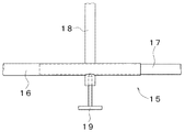
太上水平材13と太中間水平材16を垂直方向につなぐ垂直つなぎ材18を設ける。垂直つなぎ材18は、標準状態の左右一対の垂直材11の中間に位置し、太上水平材13と太中間水平材16に溶着される。
A vertical tether 18 that connects the thick horizontal member 13 and the thick middle member 16 in the vertical direction is provided. The vertical connecting member 18 is positioned between the pair of left and right vertical members 11 in the standard state, and is welded to the thick upper horizontal member 13 and the thick intermediate horizontal member 16.
垂直つなぎ材18の下方となる、太中間水平材16の細中間水平材17側の下方にロックボルト19を設ける。ロックボルト19は下方から回しやすいように上向きのネジが設けられ、ロックボルト19を締め付けるとその先端が細中間水平材17に接当し、細中間水平材17と太中間水平材16のスライドは固定される。
A lock bolt 19 is provided below the vertical intermediate member 18 on the thin intermediate horizontal member 17 side of the thick intermediate horizontal member 16. The lock bolt 19 is provided with an upward screw so that it can be easily turned from below, and when the lock bolt 19 is tightened, the tip of the lock bolt 19 comes into contact with the fine intermediate horizontal member 17, and the slide of the fine intermediate horizontal member 17 and the thick intermediate horizontal member 16 is Fixed.
ロックボルト19は下段から締め付けるものであるが、手摺枠10が取り付けられている段からロックボルト19を緩めることができるよう、ロックボルト19は布板3の上方に位置させる。
Although the lock bolt 19 is tightened from the lower stage, the lock bolt 19 is positioned above the cloth plate 3 so that the lock bolt 19 can be loosened from the stage where the handrail frame 10 is attached.
垂直材11の下端から一対の下側の押さえ金物24を設ける。押さえ金物24は垂直材11の下端から外方に水平に設けた板であり、押さえ金物24には枠組足場1建枠2の建地パイプ2aの外側にはまるUの字状の押さえ切欠き26を設け、押さえ切欠き26の開口部は各々外側に向け、建地パイプ2aと垂直材11の下部は一直線状に並ぶ。
A pair of lower presser fittings 24 are provided from the lower end of the vertical member 11. The presser foot 24 is a plate provided horizontally outward from the lower end of the vertical member 11, and the presser foot 24 has a U-shaped presser notch 26 that fits outside the building pipe 2 a of the frame scaffold 1 building frame 2. The openings of the pressing notches 26 are directed outward, and the building pipe 2a and the lower part of the vertical member 11 are aligned in a straight line.
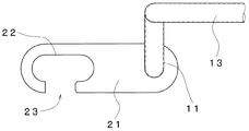
垂直材11の下端より所定距離上方から一方の垂直材11にフック金物21をもう一方の垂直材11に上側の押さえ金物25を設ける。以下便宜上、フック金物21側を左、上側の押さえ金物25を右として説明する。実施例では、フック金物21と押さえ金物25は押さえ金物24より370mm上方とした。
A hook metal member 21 is provided on one vertical member 11 and a presser metal member 25 on the upper side is provided on the other vertical member 11 from above the lower end of the vertical member 11 by a predetermined distance. For the sake of convenience, the hook hardware 21 side will be described as the left and the upper pressing metal hardware 25 will be described as the right. In the embodiment, the hook metal 21 and the presser metal 25 are 370 mm above the presser metal 24.
フック金物21は左側の垂直材11から外方に水平に設けた板であり、フック金物21には枠組足場1建枠2の建地パイプ2aの外側にはまるCの字状の長孔を有するフック切欠き22を設け、フック金物21におけるフック切欠き22の開口部23を枠組足場1の外方に向ける。
The hook hardware 21 is a plate horizontally provided outward from the left vertical member 11, and the hook hardware 21 has a C-shaped elongated hole that fits outside the building pipe 2a of the frame scaffold 1 building frame 2. A hook notch 22 is provided, and the opening 23 of the hook notch 22 in the hook hardware 21 is directed outward of the frame scaffold 1.
上側の押さえ金物25は右側の垂直材11から外方に水平に設けた板であり、押さえ金物25には枠組足場1建枠2の建地パイプ2aの外側にはまるUの字状の押さえ切欠き26を設け、押さえ切欠き26の開口部は各々外側に向ける。
The upper presser foot 25 is a plate horizontally provided outward from the right vertical member 11, and the presser foot 25 has a U-shaped presser that fits outside the building pipe 2a of the frame scaffold 1 building frame 2. Notches 26 are provided, and the opening portions of the pressing notches 26 are directed outward.
手摺枠10を枠組足場1に取り付ける際には、フック金物21と上側の押さえ金物25は枠組足場1の建枠2頂部の横桟パイプ2bより上方の建地パイプ2aに位置させる。
When the handrail frame 10 is attached to the frame scaffold 1, the hook metal 21 and the upper holding metal 25 are positioned on the building pipe 2 a above the crosspiece pipe 2 b at the top of the building frame 2 of the frame scaffold 1.
次に枠組足場1の組立、および手摺枠10の取り付け、盛り替え方法について説明する。
Next, the assembly of the frame scaffold 1, the attachment of the handrail frame 10, and the changing method will be described.
枠組足場1の組立において、1段目は必要とする幅に相当する数の建枠2を順次立設し、ブレース4で建枠2を連結する。
In assembling the frame scaffolding 1, the first stage is such that the number of building frames 2 corresponding to the required width is erected sequentially, and the building frames 2 are connected by braces 4.
図17に示すように、2段目用の手摺枠10の取り付け作業は、ロックボルト19を緩めて手摺枠10を適当な長さに伸ばし、フック金物21を左側の建枠2頂部の横桟パイプ2bより上方の建地パイプ2aに掛ける。
As shown in FIG. 17, the handrail frame 10 for the second stage is attached by loosening the lock bolt 19 and extending the handrail frame 10 to an appropriate length, and extending the hook hardware 21 to the horizontal rail at the top of the left building frame 2. It hangs on the building pipe 2a above the pipe 2b.
次に、図18に示すように、手摺枠10を伸ばして上側の押さえ金物25を右側の建枠2頂部の横桟パイプ2bより上方の建地パイプ2aに掛ける。このとき、片手で右側の垂直材11を持ち、もう一方の手でロックボルト19を持ち、ロックボルト19で左側の垂直材11を建地パイプ2aに押し付けることで、フック金物21のフック切欠き22や押さえ金物24,25の押さえ切欠き26を建地パイプ2aに押し付けることができる。
Next, as shown in FIG. 18, the handrail frame 10 is extended and the upper presser foot 25 is hung on the building pipe 2 a above the crosspiece pipe 2 b at the top of the right building frame 2. At this time, holding the right vertical member 11 with one hand, holding the lock bolt 19 with the other hand, and pressing the left vertical member 11 against the building pipe 2a with the lock bolt 19, the hook notch of the hook hardware 21 22 and presser cutouts 26 of presser hardware 24 and 25 can be pressed against the building pipe 2a.
フック金物21と押さえ金物24,25が建枠2に装着したのを確認して、ロックボルト19を締め付ける。
After confirming that the hook hardware 21 and the holding hardware 24, 25 are attached to the building frame 2, the lock bolt 19 is tightened.
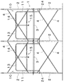
順次、隣接する建枠2に手摺枠10を取り付け、隣り合う手摺枠10では同一の建地パイプ2aにフック金物21と押さえ金物24,25が取り付けられるが、フック金物21と押さえ金物24,25は上下方向に交互に重なり合って取り付けられる。
Sequentially, the handrail frame 10 is attached to the adjacent building frame 2, and the hook hardware 21 and the presser hardware 24, 25 are attached to the same building pipe 2 a in the adjacent handrail frame 10. Are attached in an overlapping manner in the vertical direction.
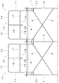
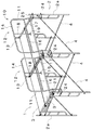
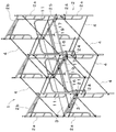
次に、図4から図7に示すように、布板3を建枠2の頂部の間に載置する。また、階段5も適宜組み立てる。その後、図8から図10に示すように、2段目の枠組足場1も同様に組み立てる。
Next, as shown in FIGS. 4 to 7, the cloth plate 3 is placed between the tops of the building frame 2. The staircase 5 is also assembled as appropriate. Thereafter, as shown in FIGS. 8 to 10, the second-stage frame scaffold 1 is assembled in the same manner.
2段目に取り付けた手摺枠10を3段目用に盛り替える(付け替える)には一人の作業者で可能である。
One worker can change the handrail frame 10 attached to the second stage for the third stage.
2段目の布板3上の作業者が、ロックボルト19を緩めて手摺枠10を縮めて取り外し、そのまま3段目用の位置まで持ち上げて取り付ける。この取り付け作業は、2段目用の手摺枠10の取り付けと同じ要領である。
An operator on the second-stage cloth board 3 loosens the lock bolt 19 and contracts and removes the handrail frame 10, and lifts and attaches it to the position for the third-stage. This attachment operation is the same as the attachment of the handrail frame 10 for the second stage.
上記のような同様の手順を繰り返し、上方に枠組足場1を形成していく。また、枠組足場1の分解を行うには、上記を逆の手順で繰り返せばよい。
The same procedure as described above is repeated to form the frame scaffold 1 above. Moreover, what is necessary is just to repeat the above in the reverse procedure, in order to decompose | disassemble the frame scaffold 1. FIG.
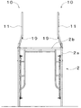
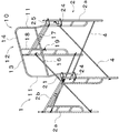
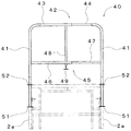
図19から図21に示すのは枠組足場1に取り付けた実施例2の先行手摺としての手摺枠40である。実施例1と同じ部分は説明を省略する。
FIGS. 19 to 21 show a handrail frame 40 as a preceding handrail of the second embodiment attached to the frame scaffold 1. Description of the same parts as those in the first embodiment is omitted.
手摺枠40には、左右一対の垂直材41と、垂直材41の上端をつなぐ上水平材42と、垂直材41の中間部をつなぐ中間水平材45とを設ける。
The handrail frame 40 is provided with a pair of left and right vertical members 41, an upper horizontal member 42 that connects the upper ends of the vertical members 41, and an intermediate horizontal member 45 that connects an intermediate portion of the vertical members 41.
垂直材41は、その側面視が垂直線状の丸鋼管である。実施例では、垂直材41の長さを約140cm、広い間隔の建枠2の一対の建地パイプ2aの妻側に取り付けた、標準状態の左右一対の垂直材41の間隔を1,219mmとした。
The vertical member 41 is a round steel pipe whose side view is a vertical line. In the embodiment, the length of the vertical member 41 is about 140 cm, and the distance between the pair of left and right vertical members 41 in the standard state, which is attached to the end of the pair of building pipes 2a of the wide frame 2 is 1,219 mm. did.
上水平材42はその中間部で二分割され、二分割された上水平材42の一方を太上水平材43とし、もう一方を細上水平材44とする。以下便宜上、太上水平材43側を左、細上水平材44側を右として説明する。
The upper horizontal member 42 is divided into two at the intermediate portion, and one of the two divided upper horizontal members 42 is a thick upper horizontal member 43 and the other is a thin upper horizontal member 44. Hereinafter, for the sake of convenience, the description will be made assuming that the thick horizontal member 43 side is on the left and the thin upper horizontal member 44 side is on the right.
左側の垂直材41と太上水平材43は、丸管を90度内側に曲げて一体に構成される。実施例では、垂直材41と太上水平材43は、外径が35mm、肉厚が1.5mmの丸鋼管とし、左側の垂直材41の中心から太上水平材43の先端までの長さを680mmとした。
The left vertical member 41 and the thick horizontal member 43 are integrally formed by bending a round tube inward by 90 degrees. In the embodiment, the vertical member 41 and the thick horizontal member 43 are round steel pipes having an outer diameter of 35 mm and a wall thickness of 1.5 mm, and the length from the center of the left vertical member 41 to the tip of the thick upper member 43. Was 680 mm.
右側の垂直材41の上部を90度内側に曲げ、その先に細上水平材44を溶着する。細上水平材44の外径は太上水平材43の内径より小さくし、細上水平材44は太上水平材43にスライド自在にはまり込む。実施例では、細上水平材44は外径が30mm、肉厚が1.5mmの丸鋼管とし、右側の垂直材41の中心から細上水平材44の先端までの長さを660mmとした。つまり、標準状態では細上水平材44は太上水平材43に約120mmはまり込む。
The upper part of the right vertical member 41 is bent inward by 90 degrees, and a thin upper horizontal member 44 is welded to the tip. The outer diameter of the fine upper horizontal member 44 is smaller than the inner diameter of the thick upper horizontal member 43, and the fine upper horizontal member 44 is slidably fitted into the thick upper horizontal member 43. In the embodiment, the fine upper horizontal member 44 is a round steel pipe having an outer diameter of 30 mm and a wall thickness of 1.5 mm, and the length from the center of the right vertical member 41 to the tip of the fine upper horizontal member 44 is 660 mm. That is, in the standard state, the thin upper horizontal member 44 fits into the thick upper horizontal member 43 by about 120 mm.
中間水平材45はその中間部で二分割され、二分割された中間水平材45の一方を太中間水平材46とし、もう一方を細中間水平材47とする。同じく、太中間水平材46側を左、細中間水平材47側を右として説明する。
The intermediate horizontal member 45 is divided into two at the intermediate portion, and one of the two divided intermediate horizontal members 45 is a thick intermediate horizontal member 46 and the other is a thin intermediate horizontal member 47. Similarly, the description will be made assuming that the thick intermediate horizontal member 46 side is left and the thin intermediate horizontal member 47 side is right.
左側の垂直材41の垂直方向中間部から内側に太中間水平材46を水平に溶着して設ける。実施例では、太中間水平材46は外径が35mm、肉厚が1.5mmの丸鋼管とし、左側の垂直材41の中心から太中間水平材46の先端までの長さを680mmとした。
A thick intermediate horizontal member 46 is horizontally welded from the vertical intermediate portion of the left vertical member 41 to the inside. In the embodiment, the thick intermediate horizontal member 46 is a round steel pipe having an outer diameter of 35 mm and a wall thickness of 1.5 mm, and the length from the center of the left vertical member 41 to the tip of the thick intermediate horizontal member 46 is 680 mm.
右側の垂直材41の垂直方向中間部から内側に細中間水平材47を水平に溶着して設ける。細中間水平材47の外径は太中間水平材46の内径より小さくし、細中間水平材47は太中間水平材46にスライド自在にはまり込む。実施例では、細中間水平材47は外径が30mm、肉厚が1.5mmの丸鋼管とし、右側の垂直材41の中心から細中間水平材47の先端までの長さを660mmとした。つまり、標準状態では細中間水平材47は太中間水平材46に約120mmはまり込む。
A thin intermediate horizontal member 47 is horizontally welded from the vertical intermediate portion of the right vertical member 41 to the inside. The outer diameter of the thin intermediate horizontal member 47 is smaller than the inner diameter of the thick intermediate horizontal member 46, and the thin intermediate horizontal member 47 is slidably fitted into the thick intermediate horizontal member 46. In the embodiment, the thin intermediate horizontal member 47 is a round steel pipe having an outer diameter of 30 mm and a wall thickness of 1.5 mm, and the length from the center of the right vertical member 41 to the tip of the thin intermediate horizontal member 47 is 660 mm. That is, in the standard state, the thin intermediate horizontal member 47 is fitted into the thick intermediate horizontal member 46 by about 120 mm.
左側の太上水平材43と太中間水平材46は平行とし、その間隔を630mmとした。また、右側の細上水平材44と細中間水平材47は平行とし、その間隔は同じく630mmとした。細上水平材44と細中間水平材47は太上水平材43と太中間水平材46に、標準状態より更に約340mmはまり込むようにした。そのため、標準状態での垂直材41の間隔1,219mmが約880mmまで縮まり、一対の建地パイプ2aの間隔が914mmのものにも取り付けられる。
The left large horizontal member 43 and the large middle horizontal member 46 are parallel and the distance between them is 630 mm. Further, the fine upper horizontal member 44 and the fine intermediate horizontal member 47 on the right side are parallel to each other, and the distance between them is also 630 mm. The fine upper horizontal member 44 and the fine intermediate horizontal member 47 are inserted into the thick upper horizontal member 43 and the thick intermediate horizontal member 46 by about 340 mm from the standard state. For this reason, the interval 1,219 mm of the vertical members 41 in the standard state is reduced to about 880 mm, and the pair of building pipes 2 a is also attached to an interval of 914 mm.
太上水平材43と太中間水平材46を垂直方向につなぐ垂直つなぎ材48を設ける。垂直つなぎ材48は、標準状態の左右一対の垂直材41の中間に位置し、太上水平材43と太中間水平材46に溶着される。
A vertical connecting member 48 is provided to connect the upper horizontal member 43 and the thick intermediate member 46 in the vertical direction. The vertical connecting member 48 is positioned between the pair of left and right vertical members 41 in the standard state, and is welded to the thick upper horizontal member 43 and the thick intermediate horizontal member 46.
垂直つなぎ材48の下方となる、太中間水平材46の細中間水平材47側の下方にロックボルト49を設ける。ロックボルト49は下方から回しやすいように上向きのネジが設けられ、ロックボルト49を締め付けるとその先端が細中間水平材47に接当し、細中間水平材47と太中間水平材46のスライドは固定される。
A lock bolt 49 is provided below the vertical intermediate member 48 on the thin intermediate horizontal member 47 side of the thick intermediate horizontal member 46. The lock bolt 49 is provided with an upward screw so that it can be easily turned from below, and when the lock bolt 49 is tightened, the tip of the lock bolt 49 comes into contact with the fine intermediate horizontal member 47, and the slide of the fine intermediate horizontal member 47 and the thick intermediate horizontal member 46 is Fixed.
ロックボルト49は下段から締め付けるものであるが、手摺枠40が取り付けられている段からロックボルト49を緩めることができるよう、ロックボルト49は布板3の上方に位置させる。
The lock bolt 49 is tightened from the lower stage, but the lock bolt 49 is positioned above the cloth plate 3 so that the lock bolt 49 can be loosened from the stage where the handrail frame 40 is attached.
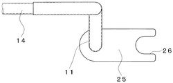
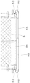
垂直材41の下端から一対の下側の押さえ金物51を設ける。押さえ金物51は垂直材51の下端から枠組足場1の方に水平に設けた板であり、押さえ金物51には枠組足場1建枠2の建地パイプ2aの外側にはまるUの字状の押さえ切欠き53を設け、押さえ切欠き53の開口部は各々外側に向け、押さえ切欠き53を垂直材41より内方に位置させ、垂直材41が建地パイプ2aの外方に位置する。
A pair of lower presser fittings 51 are provided from the lower end of the vertical member 41. The presser foot 51 is a plate provided horizontally from the lower end of the vertical member 51 toward the frame scaffold 1, and the presser foot 51 is a U-shaped presser that fits outside the building pipe 2 a of the frame scaffold 1 building frame 2. Cutouts 53 are provided, the openings of the presser cutouts 53 are directed outward, the presser cutouts 53 are positioned inward of the vertical member 41, and the vertical member 41 is positioned outward of the building pipe 2a.
垂直材41の下端より所定距離上方から一対の上側の押さえ金物52を設ける。実施例では、押さえ金物52は押さえ金物51より370mm上方とした。
A pair of upper pressers 52 are provided from above the lower end of the vertical member 41 by a predetermined distance. In the embodiment, the presser metal 52 is 370 mm above the presser metal 51.
上側の押さえ金物52はの垂直材11から枠組足場1の方に水平に設けた板であり、押さえ金物51には枠組足場1建枠2の建地パイプ2aの外側にはまるUの字状の押さえ切欠き26を設け、押さえ切欠き26の開口部は各々外側に向け、押さえ切欠き53を垂直材41より内方に位置させ、垂直材41が建地パイプ2aの外方に位置する。
The upper presser fitting 52 is a plate provided horizontally from the vertical member 11 toward the frame scaffold 1, and the presser fixture 51 has a U-shape that fits outside the building pipe 2 a of the frame scaffold 1 building frame 2. The pressing notches 26 are provided, the openings of the pressing notches 26 are directed outward, the pressing notches 53 are positioned inward of the vertical members 41, and the vertical members 41 are positioned outward of the building pipe 2a.
手摺枠40を枠組足場1に取り付ける際には、上側の押さえ金物52は枠組足場1の建枠2頂部の横桟パイプ2bより上方の建地パイプ2aに位置させる。
When the handrail frame 40 is attached to the frame scaffold 1, the upper presser foot 52 is positioned on the building pipe 2 a above the horizontal beam pipe 2 b at the top of the building frame 2 of the frame scaffold 1.
次に、手摺枠40の取り付け、盛り替え方法について説明する。
Next, a method for attaching and changing the handrail frame 40 will be described.
2段目用の手摺枠40の取り付け作業は、ロックボルト49を緩めて手摺枠40を適当な長さに伸ばし、上側の押さえ金物52を左側の建枠2頂部の横桟パイプ2bより上方の建地パイプ2aに掛ける。
To install the second-stage handrail frame 40, loosen the lock bolt 49 to extend the handrail frame 40 to an appropriate length, and move the upper presser foot 52 above the horizontal beam pipe 2b at the top of the left building frame 2. Hang on the construction pipe 2a.
手摺枠40を伸ばして上側の押さえ金物52を右側の建枠2頂部の横桟パイプ2bより上方の建地パイプ2aに掛ける。このとき、片手で右側の垂直材41を持ち、もう一方の手でロックボルト49を持ち、ロックボルト49で左側の垂直材41を建地パイプ2aに押し付けることで、押さえ金物51,52の押さえ切欠き53を建地パイプ2aに押し付けることができる。
The handrail frame 40 is extended and the upper presser foot 52 is hung on the building pipe 2a above the horizontal beam pipe 2b at the top of the right building frame 2. At this time, holding the right vertical member 41 with one hand, holding the lock bolt 49 with the other hand, and pressing the left vertical member 41 against the building pipe 2a with the lock bolt 49, hold down the holding hardware 51, 52. The notch 53 can be pressed against the building pipe 2a.
押さえ金物51,52が建枠2に装着したのを確認して、ロックボルト49を締め付ける。
After confirming that the presser fittings 51 and 52 are attached to the building frame 2, tighten the lock bolt 49.
2段目に取り付けた手摺枠40を3段目用に盛り替える(付け替える)には一人の作業者で可能である。
One worker can change the handrail frame 40 attached to the second stage for the third stage.
2段目の布板3上の作業者が、ロックボルト49を緩めて手摺枠40を縮めて取り外し、そのまま3段目用の位置まで持ち上げて取り付ける。この取り付け作業は、2段目用の手摺枠40の取り付けと同じ要領である。
An operator on the second-stage cloth board 3 loosens the lock bolt 49, shrinks and removes the handrail frame 40, and lifts and attaches it to the position for the third-stage as it is. This attachment operation is the same as the attachment of the handrail frame 40 for the second stage.
上記のような同様の手順を繰り返し、上方に枠組足場1を形成していく。また、枠組足場1の分解を行うには、上記を逆の手順で繰り返せばよい。
The same procedure as described above is repeated to form the frame scaffold 1 above. Moreover, what is necessary is just to repeat the above in the reverse procedure, in order to decompose | disassemble the frame scaffold 1. FIG.
図22から図23には、桁側に手摺枠10を、妻側に手摺枠40を取り付ける例を示しており、全周に取り付けることにより、親綱や安全帯を使用することなく作業ができるので、作業効率と安全性が向上する。
22 to 23 show an example in which the handrail frame 10 is attached to the girder side and the handrail frame 40 is attached to the wife side. By attaching the handrail frame 40 to the entire circumference, the work can be performed without using the master rope or the safety belt. So work efficiency and safety are improved.
以上の実施例では、太上水平材13,43と太中間水平材16,46を左側に、細上水平材14,44と細中間水平材17,47を右側に配置した例を示したが、左右が逆になるのはもちろん、交互に入れ替わっても良い。
In the above embodiment, the thick upper horizontal members 13, 43 and the thick intermediate horizontal members 16, 46 are arranged on the left side, and the thin upper horizontal members 14, 44 and the thin intermediate horizontal members 17, 47 are arranged on the right side. Of course, the left and right sides may be reversed, and they may be interchanged.
また、ロックボルト19,49として上向きのネジによるものを示したが、ロックボルト19,49は太中間水平材16,46の下方に設けられれば良く、水平方向のネジとしても良い。
Further, although the lock bolts 19 and 49 are formed by upward screws, the lock bolts 19 and 49 may be provided below the thick intermediate horizontal members 16 and 46, and may be horizontal screws.
また、手摺枠10,40を盛り替えて最上段にのみ取り付ける例を示したが、全ての段に取り付けるようにしても良い。
Moreover, although the example in which the handrail frames 10 and 40 are rearranged and attached only to the uppermost stage is shown, they may be attached to all the stages.
枠組足場のスライド式先行手摺の第一実施例を示す正面図である。It is a front view which shows the 1st Example of the slide type preceding handrail of a frame scaffold.
その側面図である。It is the side view.
その斜視図である。FIG.
図1の布板を載置した図である。It is the figure which mounted the cloth board of FIG.
その側面図である。It is the side view.
その平面図である。FIG.
その斜視図である。FIG.
図4の2段目の枠組足場を組み立てた図である。It is the figure which assembled the frame scaffolding of the 2nd step of FIG.
その側面図である。It is the side view.
その斜視図である。FIG.
その要部を示す部分拡大図である。It is the elements on larger scale which show the principal part.
図11の平面図である。It is a top view of FIG.
図11の要部を示す部分拡大図である。It is the elements on larger scale which show the principal part of FIG.
図11の要部を示す部分拡大断面図である。It is a partial expanded sectional view which shows the principal part of FIG.
図12の要部を示す部分拡大図である。It is the elements on larger scale which show the principal part of FIG.
図12の要部を示す部分拡大図である。It is the elements on larger scale which show the principal part of FIG.
第一実施例の先行手摺を取り付ける作業状態を示す図である。It is a figure which shows the operation | work state which attaches the preceding handrail of a 1st Example.
図17の続きの作業状態を示す図である。FIG. 18 is a diagram illustrating a work state continued from FIG. 17.
枠組足場のスライド式先行手摺の第二実施例を示す正面図である。It is a front view which shows the 2nd Example of the sliding type | formula handrail of a frame scaffold.
その側面図である。It is the side view.
その平面図である。FIG.
第一実施例及び第二実施例の先行手摺を取り付ける作業状態を示す図である。It is a figure which shows the operation state which attaches the preceding handrail of 1st Example and 2nd Example.
図22の続きの作業状態を示す図である。FIG. 23 is a diagram showing a working state following FIG.
符号の説明Explanation of symbols
1 枠組足場
2 建枠
2a 建地パイプ
2b 横桟パイプ
3 布板
10 手摺枠
11 垂直材
12 上水平材
13 太上水平材
14 細上水平材
15 中間水平材
16 太中間水平材
17 細中間水平材
19 ロックボルト
21 フック金物
22 フック切欠き
23 開口部
24 押さえ金物
25 押さえ金物
26 押さえ切欠き
40 手摺枠
41 垂直材
42 上水平材
43 太上水平材
44 細上水平材
45 中間水平材
46 太中間水平材
47 細中間水平材
49 ロックボルト
51 押さえ金物
52 押さえ金物
53 押さえ切欠き
1 framework scaffold 2 building frame
2a Construction pipe
2b Horizontal cross pipe 3 Cloth board
10 Handrail frame
11 Vertical material
12 Upper horizontal material
13 Thick top horizontal material
14 Fine horizontal material
15 Intermediate horizontal material
16 Thick middle horizontal material
17 Fine intermediate horizontal material
19 Rock bolt
21 Hook hardware
22 Hook notch
23 opening
24 Presser hardware
25 Presser hardware
26 Presser cutout
40 handrail frame
41 Vertical material
42 Upper horizontal material
43 Thick horizontal material
44 Fine horizontal material
45 Intermediate horizontal material
46 Thick middle horizontal material
47 Fine intermediate horizontal material
49 Rock bolt
51 Presser hardware
52 Pressing hardware
53 Presser notch