JP2005299329A - Building - Google Patents
Building Download PDFInfo
- Publication number
- JP2005299329A JP2005299329A JP2004120586A JP2004120586A JP2005299329A JP 2005299329 A JP2005299329 A JP 2005299329A JP 2004120586 A JP2004120586 A JP 2004120586A JP 2004120586 A JP2004120586 A JP 2004120586A JP 2005299329 A JP2005299329 A JP 2005299329A
- Authority
- JP
- Japan
- Prior art keywords
- wall
- floor
- bearing
- walls
- load
- Prior art date
- Legal status (The legal status is an assumption and is not a legal conclusion. Google has not performed a legal analysis and makes no representation as to the accuracy of the status listed.)
- Pending
Links
- 239000000463 material Substances 0.000 claims abstract description 43
- 238000010008 shearing Methods 0.000 abstract 2
- 229910000831 Steel Inorganic materials 0.000 description 16
- 239000010959 steel Substances 0.000 description 16
- 238000005452 bending Methods 0.000 description 7
- 238000010276 construction Methods 0.000 description 7
- 239000000853 adhesive Substances 0.000 description 4
- 230000001070 adhesive effect Effects 0.000 description 4
- 238000000034 method Methods 0.000 description 3
- 238000005192 partition Methods 0.000 description 3
- 239000011120 plywood Substances 0.000 description 3
- 230000003014 reinforcing effect Effects 0.000 description 3
- 230000015572 biosynthetic process Effects 0.000 description 1
- 238000005219 brazing Methods 0.000 description 1
- 210000002837 heart atrium Anatomy 0.000 description 1
Images
Landscapes
- Load-Bearing And Curtain Walls (AREA)
Abstract
Description
本発明は、建物に関する。 The present invention relates to a building.
近年、住宅の構築については、その工業化が進み、例えば、プレハブ住宅等においては、柱、梁等をあまり使用せずに、予め工場で形成された床パネル、壁パネル、天井パネル等の矩形板状のパネルを配列していくことにより、床、壁、天井等を形成していく施工方法(以下、パネル工法)が知られている。 In recent years, the construction of houses has been industrialized. For example, in prefabricated houses, rectangular plates such as floor panels, wall panels, ceiling panels, etc. that have been formed in the factory in advance without using columns and beams. There is known a construction method (hereinafter referred to as a panel construction method) for forming floors, walls, ceilings, and the like by arranging shaped panels.
工場で組み立てられた床用・壁用・屋根用等のパネルは、トラック等で施工現場に運び込まれる。建築現場では、パネルの配設とパネル間の接合作業を行うだけで、短期間で床、壁、屋根等の住宅の基本構造を構築することができる。 Panels for floors, walls, roofs, etc. assembled at the factory are brought to the construction site by trucks. In a construction site, a basic structure of a house such as a floor, a wall, and a roof can be constructed in a short period of time simply by arranging the panels and joining the panels.
パネル工法で構築される住宅において、例えば家屋下のガレージ等、幅広の開口が要求される場合には、水平方向に伸びる梁部と、梁部の両端から鉛直下方に伸びる柱部とからなる門型パネルが適用される。また、所定間隔をおいて1対の門型パネルを対向させ、両者の柱部を壁パネルで結合するとともに、梁部を床パネルで結合した門型パネルユニットを用いるものもある(例えば、特許文献1参照)。
ところで、完成した住宅に長期間居住する場合には、家族の成長や独立のために、間取りや仕様の変更を行う必要が生じる。このため、大空間の部屋をあらかじめ形成し、そこに非耐力壁の間仕切を設けることで、完成後においても容易に間取り変更を行うことができるようにした住宅が設計されている。 By the way, when living in a completed house for a long period of time, it is necessary to change the layout and specifications for the growth and independence of the family. For this reason, a house has been designed in which a room of a large space is formed in advance and a partition of a non-bearing wall is provided therein so that the floor plan can be easily changed even after completion.
しかし、外壁等の耐力壁に即して大空間の部屋を設けると、耐力壁にかかる水平力が耐力壁のせん断耐力を上回る恐れがある。 However, if a large space is provided in conformity with the load-bearing wall such as the outer wall, the horizontal force applied to the load-bearing wall may exceed the shear strength of the load-bearing wall.
本発明の課題は、耐力壁に即して大空間の部屋を設けた場合にも、水平力に抵抗するせん断耐力を耐力壁に期待することができる建物を提供することである。 The subject of this invention is providing the building which can expect the shear strength resisting horizontal force to a load bearing wall, even when the room of a large space is provided according to the load bearing wall.
以上の課題を解決するため、請求項1に記載の発明は、建物であって、図1〜5に示すように、躯体を構成する耐力壁(外壁1E、1W、1S)の少なくとも一方の面に該耐力壁(外壁1E、1W、1S)と一体に床状構造材25、35が設けられていることを特徴とする。
In order to solve the above problems, the invention described in claim 1 is a building, and as shown in FIGS. 1 to 5, at least one surface of the load-bearing walls (outer walls 1 </ b> E, 1 </ b> W, 1 </ b> S) constituting the housing. Further, floor-shaped structural members 25 and 35 are provided integrally with the load-bearing walls (
ここで、床状構造材とは、耐力壁に垂直な方向の幅が、鉛直方向の高さよりも大きい部材であり、耐力壁に作用する水平力を負担するが、鉛直荷重は必ずしも支持しなくてもよい。床状構造材としては、例えば床パネル等を用いることができるが、耐力壁に垂直な方向の幅よりも梁成が小さい梁材等を用いてもよい。 Here, the floor-shaped structural material is a member whose width in the direction perpendicular to the bearing wall is larger than the height in the vertical direction and bears a horizontal force acting on the bearing wall, but does not necessarily support the vertical load. May be. As the floor structure material, for example, a floor panel or the like can be used, but a beam material or the like having a beam formation smaller than the width in the direction perpendicular to the bearing wall may be used.
請求項1に記載の発明によれば、躯体を構成する耐力壁(外壁1E、1W、1S)の少なくとも一方の面に該耐力壁(外壁1E、1W、1S)と一体に床状構造材25、35が設けられているので、耐力壁(外壁1E、1W、1S)に作用する水平力を床状構造材25、35に負担させることができる。したがって、耐力壁(外壁1E、1W、1S)に即して大空間の部屋を設けた場合にも、水平力に抵抗するせん断耐力を耐力壁(外壁1E、1W、1S)に期待することができる。
According to the first aspect of the present invention, the floor-shaped structural member 25 is integrated with the load-bearing walls (
請求項2に記載の発明は、請求項1に記載の建物であって、図2(b)に示すように、前記床状構造材35の前記耐力壁(外壁1E、1W)と反対側の端部には、該耐力壁(外壁1E、1W)と平行に壁体(支持壁40E、40W)が設けられていることを特徴とする。
Invention of Claim 2 is a building of Claim 1, Comprising: As shown in FIG.2 (b), the said load-bearing wall (
請求項2に記載の発明によれば、前記床状構造材35の前記耐力壁(外壁1E、1W)と反対側の端部には、該耐力壁(外壁1E、1W)と平行に壁体(支持壁40E、40W)が設けられているので、H形鋼と同様の断面H形状の梁構造20、50を形成することができ、曲がりやねじれに対する剛性をさらに高めることができる。したがって、耐力壁を少なくすることができ、幅広の開口や大空間の部屋を設けることができる。
According to the second aspect of the present invention, a wall body parallel to the load-bearing wall (
請求項3に記載の発明は、請求項2に記載の建物であって、前記壁体(支持壁40E、40W)の下部には該壁体(支持壁40E、40W)を支持する梁材41E、41Wが前記耐力壁(外壁1E、1W)と平行に設けられていることを特徴とする。
Invention of Claim 3 is the building of Claim 2, Comprising: The
請求項3に記載の発明によれば、前記壁体(支持壁40E、40W)の下部には該壁体(支持壁40E、40W)を支持する梁材41E、41Wが前記耐力壁(外壁1E、1W)と平行に設けられているので、梁材41E、41Wにより壁体(支持壁40E、40W)の荷重を支持することができるとともに、壁体(支持壁40E、40W)とともに梁材41E、41Wにより水平力を伝達することができる。
According to the third aspect of the present invention, the
請求項4に記載の発明は、請求項2または3に記載の建物であって、2つの前記壁体(支持壁40E、40W)が対向して躯体の両端部に設けられるとともに、前記壁体(支持壁40E、40W)に垂直な梁材(H形鋼43)で互いに接続されていることを特徴とする。
Invention of Claim 4 is a building of Claim 2 or 3, Comprising: Two said wall bodies (
請求項4に記載の発明によれば、2つの前記壁体(支持壁40E、40W)が対向して躯体の両端部に設けられるとともに、前記壁体(支持壁40E、40W)に垂直な梁材(H形鋼43)で互いに接続されているので、2つの壁体(支持壁40E、40W)の間に大空間の居室を設けることができる。
According to the fourth aspect of the present invention, the two wall bodies (
請求項5に記載の発明は、請求項4に記載の建物であって、前記壁体(支持壁40E、40W)及び前記壁体(支持壁40E、40W)に垂直な梁材(H形鋼43)は屋根(屋根パネル44)を支持することを特徴とする。
Invention of Claim 5 is the building of Claim 4, Comprising: The beam material (H-section steel) perpendicular | vertical to the said wall body (
請求項5に記載の発明によれば、前記壁体(支持壁40E、40W)及び前記壁体(支持壁40E、40W)に垂直な梁材(H形鋼43)は屋根(屋根パネル44)を支持するので、建物の最上階に大空間の居室を設けることができる。
According to the invention described in claim 5, the wall (
請求項6に記載の発明は、請求項5に記載の建物であって、前記壁体(支持壁40E、40W)に垂直な梁材(H形鋼43)は前記壁体(支持壁40E、40W)の上端部に接続されていることを特徴とする。
Invention of Claim 6 is the building of Claim 5, Comprising: The beam material (H-section steel 43) perpendicular | vertical to the said wall body (
請求項6に記載の発明によれば、前記壁体(支持壁40E、40W)に垂直な梁材(H形鋼43)は前記壁体(支持壁40E、40W)の上端部に接続されているので、大空間の居室の天井高さを高くすることができる。
According to invention of Claim 6, the beam material (H-section steel 43) perpendicular | vertical to the said wall body (
本発明によれば、躯体を構成する耐力壁の少なくとも一方の面に該耐力壁と一体に床状構造材を設けることで、耐力壁に作用する水平力を床状構造材に負担させることができる。したがって、耐力壁に即して大空間の部屋を設けた場合にも、水平力に抵抗するせん断耐力を耐力壁に期待することができる。 According to the present invention, by providing the floor-shaped structural material integrally with the load-bearing wall on at least one surface of the load-bearing wall constituting the housing, it is possible to load the floor-shaped structural material with the horizontal force acting on the load-bearing wall. it can. Therefore, even when a large space is provided in line with the bearing wall, it is possible to expect the shear wall to resist the horizontal force.
また、床状構造材の耐力壁と反対側の端部に、該耐力壁と平行に壁体を設けることで、H形鋼と同様の断面H形状の梁構造を形成することができ、曲がりやねじれに対する剛性をさらに高めることができる。したがって、耐力壁を少なくすることができ、幅広の開口や大空間の部屋を設けることができる。 Also, by providing a wall body in parallel with the load bearing wall at the end opposite to the load bearing wall of the floor structure material, a beam structure with a H-shaped cross section similar to that of H-section steel can be formed and bent. Further, the rigidity against twisting can be further increased. Therefore, the load-bearing wall can be reduced, and a wide opening and a large space can be provided.
また、壁体の下部に、壁体を支持する梁材を耐力壁と平行に設けることで、梁材により壁体の荷重を支持することができるとともに、壁体とともに梁材により水平力を伝達することができる。 In addition, by providing a beam material that supports the wall body in the lower part of the wall body in parallel with the load-bearing wall, the load of the wall body can be supported by the beam material, and horizontal force is transmitted by the beam material together with the wall body. can do.
さらに、2つの壁体を対向させて躯体の両端部に設け、壁体に垂直な梁材で互いに接続することで、2つの壁体の間に大空間の居室を設けることができる。 Furthermore, a large space living room can be provided between the two walls by providing two walls facing each other at both ends of the housing and connecting them with a beam material perpendicular to the walls.
また、壁体及び壁体に垂直な梁材が屋根を支持することで、建物の最上階に大空間の居室を設けることができる。 In addition, the wall and the beam material perpendicular to the wall support the roof, so that a large room can be provided on the top floor of the building.
さらに、壁体に垂直な梁材を、壁体の上端部に接続させることで、大空間の居室の天井高さを高くすることができる。 Furthermore, the ceiling height of the large room can be increased by connecting a beam member perpendicular to the wall to the upper end of the wall.
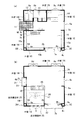
以下、本発明の実施の形態について詳細に説明する。図1は本発明を実施した建物を示す間取り図であり、(a)は1階の間取り図、(b)は2階の間取り図である。 Hereinafter, embodiments of the present invention will be described in detail. FIG. 1 is a floor plan showing a building in which the present invention is implemented. (A) is a floor plan of the first floor, and (b) is a floor plan of the second floor.
この建物は、桟材を矩形枠状に組み立て、この矩形枠内に必要に応じて補強桟材を縦横に組み付け、両面もしくは片面に合板等の面材を貼りつけたパネルを予め工場等で形成し、これを床、壁、屋根等の構造材として用い、施工現場でこれらのパネルを組み立てることにより住宅を構築するパネル工法を用いて構築されている。 In this building, the bars are assembled in a rectangular frame shape, and reinforcing bars are vertically and horizontally assembled in the rectangular frame as necessary, and panels with plywood and other face materials attached to both sides or one side are pre-formed at the factory, etc. However, this is used as a structural material such as a floor, a wall, and a roof, and is constructed by using a panel method for constructing a house by assembling these panels at a construction site.
西側の外壁1Wには、図1(a)に示すように、玄関11が設けられている。玄関11と隣接した北西の角部には浴室12が設けられており、玄関11と浴室12との間は、壁5aにより仕切られている。
As shown in FIG. 1A, the
また、浴室12に隣接して洗面所兼トイレ13が設けられている。1階の北東にはキッチン14が設けられている。浴室12、洗面所兼トイレ13、キッチン14の北側の外壁1Nには、それぞれ窓8a、8b、8cが設けられている。
A bathroom and
1階の南半分はリビングルーム15となっている。リビングルーム15はキッチン14と一体化した大空間を形成している。また、玄関11とリビングルーム15との間には、西側の外壁1Wと垂直な壁5bが設けられている。
The
リビングルーム15の西側半分は、図1(b)に示すように、吹き抜け部17となっている。この吹き抜け部17の部分に、壁5bに沿って、2階へ通じる階段16が設けられている。
As shown in FIG. 1B, the west half of the
東側の外壁1Eには、玄関11と対向する位置に、小開口部6aが設けられている。小開口部6aの南側には、幅約45cmの耐力壁2aが設けられている。なお、耐力壁2aは2階まで連続している。
In the
東側の外壁1Eの南端には、外壁1Eを構成する壁パネルと、幅約45cmの3枚の壁パネル4a、4b、4cとを合わせて、角柱状に組んで形成された柱構造3Eが設けられている。また、西側の外壁1Wと南側の外壁1Sとの接合部には、西側及び南側の外壁1W、1Sを構成する壁パネルと、幅約45cmの2枚の壁パネル4d、4eとを合わせて、角柱状に組んで形成された柱構造3Wが設けられている。
At the south end of the
柱構造3Eと3Wと中間位置には、幅約45cmの耐力壁2bが南北方向に設けられている。なお、耐力壁2bは2階まで連続している。耐力壁2bの北側の端と柱構造との間には、床から天井まで届く高さの大開口部7aが設けられている。耐力壁2bは屋根まで連続しており、耐力壁2bの南側の端と西側の柱構造3Wとの間には、南側の外壁1Sが設けられている。耐力壁2bと外壁1Sとは垂直である。また、外壁1Wと壁パネル4dとは垂直であり、外壁1Sと壁パネル4eとは垂直である。
A bearing
耐力壁2aと、柱構造3Eとの間には、東側の外壁1Eに沿って奥行き約45cmの壁付け収納ユニット15aが設けられている。また、耐力壁2bと柱構造3Wとの間にも、南側の外壁1Sに沿って奥行き約45cmの壁付け収納ユニット15bが設けられている。また、玄関11とリビングルーム15の間の壁と、柱構造3Wとの間にも、西側の外壁1Wに沿って奥行き約45cmの壁付け収納ユニット15cが設けられている。壁付け収納ユニット15a、15b、15cは同じ大きさであり、位置を交換することができる。
Between the bearing
2階は大空間の1つの居室となっており、図示しない間仕切壁により任意の間取りに仕切ることができる。2階では、図1(b)に示すように、西側の外壁1Wの玄関11の上部に、庇21が設けられるとともに、小開口部6bが設けられている。小開口部6bの北側には、壁5aと連続する耐力壁2cが設けられている。また、小開口部6bの南側には、壁5bと連続する耐力壁2dが設けられている。
東側の外壁1Eの小開口部6aの上部には、小開口部6cが設けられている。
The second floor is one room in a large space, and can be partitioned into an arbitrary floor plan by a partition wall (not shown). On the second floor, as shown in FIG. 1 (b), an
A
北側の外壁1Nには、窓8a、8bの上部に窓8dが、窓8cの上部に窓8eが設けられている。また、耐力壁2bと柱構造3Eとの間には、大開口部7bが設けられている。なお、大開口部7aと大開口部7bとの間には、庇22が設けられるとともに、図示しない梁が設けられている。図示しない梁は、東側の柱構造3Eと耐力壁2bによって支持されている。2階の床24の南側の端部は、東側の柱構造3Eと図示しない梁とによって支持されている。
On the
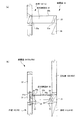
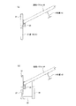
南側の外壁1Sには、採光用の小窓9が形成されている。また、壁付け収納ユニット15b、15cの上部には、幅約45cmの床状構造材25が2階の床24と同じ高さに設けられている。この床状構造材25は、パネル工法で用いられる床パネルであり、図2(a)に示すように、矩形枠状の框材25aに必要に応じて補強桟材が設けられ、上面に合板25bが貼られて形成されている。
A
床状構造材25の外壁1W(1S)に垂直な方向の幅は、鉛直方向の高さよりも大きい。したがって、床状構造材25に作用する鉛直荷重よりも外壁1W(1S)に垂直な方向に作用する水平力に対してより強い曲げ耐力を発揮することができる。
The width of the floor-shaped structural member 25 in the direction perpendicular to the
床状構造材25の框材25aの外壁1W(1S)側の端部は、外壁1W(1S)により支持されている。また、床状構造材25の框材25aの外壁1W(1S)と反対側の端部は、外壁1W(1S)と平行に設けられた梁材26により支持されている。
An end of the floor structure material 25 on the side of the
梁材26は、柱構造3Wと、耐力壁2bまたは2dにより両端部を支持されている。梁材26の上部には、床状構造材25の端部と接して半割材27が設けられている。
また、床状構造材25の外壁1W(1S)と垂直な両端部は、壁5b及び壁パネル4d(耐力壁2b及び壁パネル4e)により支持されている。
Both ends of the
Further, both end portions of the floor-shaped structural member 25 perpendicular to the
このように、外壁1W(1S)の内側面に沿って、床状構造材25が外壁1W(1S)と一体に設けられているので、外壁1W(1S)に作用する面方向の水平力や面に垂直な方向の水平力を床状構造材25に負担させることができ、水平力に抵抗するせん断耐力や曲げ耐力を増大させることができる。したがって、外壁1W(1S)に即して大空間の部屋を設けることができる。
Thus, since the floor-like structural member 25 is provided integrally with the
また、外壁1W(1S)、床状構造材25、梁材26は緊結されて一体化しており、H形鋼と同様の断面略H形状の梁構造20を形成する。このため、外壁1W(1S)、梁材26がウェブ、床状構造材25がフランジの役割を果たし、曲がりやねじれに対する剛性をさらに高めることができる。
Further, the
図2(b)は、屋根の高さにおける東側の外壁1Eまたは西側の外壁1Wの鉛直断面図である。2階を大空間の1つの居室とするために、東側の外壁1E及び西側の外壁1Wの上部には、図2(b)に示すような構造が設けられている。すなわち、外壁1E(1W)と所定間隔離間し、かつ外壁1E(1W)と平行に、支持壁40E(40W)が配置されている。
FIG. 2B is a vertical sectional view of the
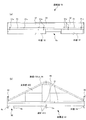
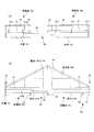
東側の外壁1Eの上部には、図3(a)に示すように、胴差31及びパラペット壁32が設けられている。パラペット壁32は、胴差ボルト31aや接着剤等により、外壁1Eと接合されている。パラペット壁32は、外壁1Eの上端を同じ高さに形成している。パラペット壁32は図4(a)に示すように、西側の外壁1Wの上部にも同様に設けられている。また、図5に示すように、北側、南側の外壁1N、1Sの上部にも同様にパラペット壁32が設けられている。
As shown in FIG. 3A, a
支持壁40Eは、外壁1Eと平行に設けられた梁材41Eにより、胴差31を介して支持されている。支持壁40Eと胴差31、及び胴差31と梁材41Eとは図示しない胴差ボルトや接着剤により緊結されている。
The
梁材41Eは、図3(b)に示すように、外壁1N、耐力壁2a、及び柱構造3Eにより支持されている。外壁1Eの上部の胴差31と支持壁40Eの下部の胴差31との対向する面には、図2(b)に示すように、同じ高さに床受け材33が設けられている。
As shown in FIG. 3B, the
床受け材33はスクリュー釘34や接着剤等により、外壁1E及び外壁1Eの上部の胴差31、または支持壁40Eの下部の胴差31及び針材41Eに緊結されている。床受け材33の上には床状構造材35が配置されている。
The
この床状構造材35は、パネル工法で用いられる床パネルであり、図2(b)に示すように、矩形枠状の框材35aに必要に応じて補強桟材が設けられ、上面に合板35bが貼られて形成されている。床状構造材35は、床受け材34と同様に、スクリュー釘34や接着剤等により、外壁1Eの上部の胴差31及び支持壁40Eの下部の胴差31に緊結されている。
This floor-shaped structural member 35 is a floor panel used in the panel method, and as shown in FIG. 2 (b), a reinforcing frame member is provided on a rectangular frame-shaped
床状構造材35の外壁1E(1W)に垂直な方向の幅は、鉛直方向の高さよりも大きい。したがって、床状構造材35に作用する鉛直荷重よりも外壁1E(1W)に垂直な方向に作用する水平力に対してより強い曲げ耐力を発揮することができる。
The width of the floor-shaped structural member 35 in the direction perpendicular to the
床状構造材35の框材25aの外壁1E(1W)側の端部は、外壁1E(1W)に設けられた床受け材33により支持されている。また、床状構造材25の框材25aの外壁1E(1W)と反対側の端部は、梁材41E(41W)に設けられた床受け材33により支持されている。また、床状構造材35の外壁1E(1W)と垂直な両端部は、外壁1N、柱構造3E(外壁1N、耐力壁2c、または柱構造3W、耐力壁2d)により支持されている。
An end of the floor structure material 35 on the
このように、外壁1E(1W)の内側面に沿って、床状構造材35が外壁1E(1W)と一体に設けられているので、外壁1E(1W)に作用する面方向の水平力や面に垂直な方向の水平力を床状構造材35に負担させることができ、水平力に抵抗するせん断耐力や曲げ耐力を増大させることができる。したがって、外壁1E(1W)に即して大空間の部屋を設けることができる。
As described above, since the floor-shaped structural member 35 is provided integrally with the
また、外壁1E(1W)と支持壁40E(40W)とが所定間隔離間し、かつ平行に配置されており、両者を胴差31を介して床状構造材35により緊結することで、H形鋼と同様の断面H形状の梁構造50を形成することができる。このため、外壁1E(1W)、支持壁40E(40W)及び梁材41E(41W)がウェブ、床状構造材35がフランジの役割を果たし、曲がりやねじれに対する剛性をさらに高めることができる。
Further, the
なお、建物の西側には、図1に示すように、玄関11及び小開口部6bの部分に凹部が設けられているため、図4(a)に示すように、玄関11及び小開口部6bの部分には西側の外壁1Wがない。
In addition, since the recessed part is provided in the part of the
支持壁40Wは、図4(b)に示すように、支持壁40Wの下部に設けられた梁材41Wにより支持されている。梁材41Wは、北側の外壁1N、耐力壁2c、2d、及び柱構造3Wにより支持されている。
As shown in FIG. 4B, the
外壁1Wと支持壁40Wとの間には、東側と同様に、胴差31や床受け材33、床状構造材35等が設けられている。しかし、玄関11及び小開口部6bの部分には西側の外壁1Wがないため、断面H形状の北側の梁構造50aと、断面H形状の南側の梁構造50bとが分かれて形成されている。梁構造50aの南端は耐力壁2cと接続されており、梁構造50bの北端は耐力壁2dと接続されている。
Between the
小開口部6bの上部には、耐力壁2cと耐力壁2dとの間に、庇42が設けられている。この庇42と支持壁40Wとにより、梁構造50aと梁構造50bとの間で水平方向の荷重を伝達することができる。
On the upper portion of the
支持壁40E及び支持壁40Wは、上端でH形鋼43を支持している。H形鋼43は、支持壁40Eと支持壁40Wとの間に渡されており、屋根パネル44を支持している。屋根パネル44は、図5(a)に示すように、H形鋼43に支持されるとともに、外壁1N(1S)に設けられた屋根受け材36に端部を支持されている。
The
なお、大開口部7bの上部では、図5(b)に示すように、外壁1Sと面一に設けられた梁材37の上部にパラペット壁32及び屋根受け材36が設けられている。また、梁材37と平行に補助壁材38が設けられており、梁材37及び補助壁材38は柱構造3E及び耐力壁2bにより両端部を支持されている。また、梁材37及び補助壁材38の下端は軒下材39により接続されている。屋根パネル44は、H形鋼43に支持されるとともに、屋根受け材36、補助壁材38によっても支持されている。
In addition, in the upper part of the
支持壁40Eと支持壁40Wとの間に、屋根パネル44を支持するH形鋼43が渡されていることで、2階に耐力壁がない大空間の居室を設けることができる。また、非耐力壁の間仕切を任意に設けることができ、完成後においても容易に間取りを行うことができる。
Since the H-shaped steel 43 that supports the
なお、以上の実施の形態においては、切妻屋根の建物としたが、その他の屋根形状にしてもよい。また、吹き抜け部17の位置や、その他の間取りや方角についても適宜変更可能であることはもちろんである。
In addition, in the above embodiment, it was set as the building of a gable roof, However, You may make it another roof shape. Of course, the position of the blow-
1N、1E、1W、1S 外壁
25、35 床状構造材
40E、40W 支持壁
41E、41W 梁材
43 H形鋼
44 屋根パネル
20、50、50a、50b 梁構造
1N, 1E, 1W, 1S Outer wall 25, 35
Claims (6)
Priority Applications (1)
| Application Number | Priority Date | Filing Date | Title |
|---|---|---|---|
| JP2004120586A JP2005299329A (en) | 2004-04-15 | 2004-04-15 | Building |
Applications Claiming Priority (1)
| Application Number | Priority Date | Filing Date | Title |
|---|---|---|---|
| JP2004120586A JP2005299329A (en) | 2004-04-15 | 2004-04-15 | Building |
Related Child Applications (1)
| Application Number | Title | Priority Date | Filing Date |
|---|---|---|---|
| JP2010003607A Division JP4923113B2 (en) | 2010-01-12 | 2010-01-12 | building |
Publications (1)
| Publication Number | Publication Date |
|---|---|
| JP2005299329A true JP2005299329A (en) | 2005-10-27 |
Family
ID=35331210
Family Applications (1)
| Application Number | Title | Priority Date | Filing Date |
|---|---|---|---|
| JP2004120586A Pending JP2005299329A (en) | 2004-04-15 | 2004-04-15 | Building |
Country Status (1)
| Country | Link |
|---|---|
| JP (1) | JP2005299329A (en) |
-
2004
- 2004-04-15 JP JP2004120586A patent/JP2005299329A/en active Pending
Similar Documents
| Publication | Publication Date | Title |
|---|---|---|
| CN103452188A (en) | Storey Height Reduced Sectional Steel Frame Using U-shaped Composite Beams | |
| KR20180092128A (en) | Module type building structure | |
| JP4923113B2 (en) | building | |
| JPH1046664A (en) | Beam penetration type steel frame system | |
| JP7759206B2 (en) | Buildings and their construction methods | |
| JP4355244B2 (en) | building | |
| JP2005299329A (en) | Building | |
| JP2006045962A (en) | Building | |
| JP2019065637A (en) | Column-beam structure of plate-form building | |
| EP3119951A1 (en) | Attachment components for securing portions of a structure with integrated insulation to one another | |
| JPH08135217A (en) | House | |
| JP3943438B2 (en) | building | |
| JPH011840A (en) | Frame structure for small buildings such as sunrooms | |
| JP2005307509A (en) | Building | |
| JP7286375B2 (en) | building | |
| JP4898288B2 (en) | Stairwell reinforcement structure | |
| JP4642378B2 (en) | building | |
| JP2003082791A (en) | Wall with openings | |
| JP2002339483A (en) | Prefabricated bearing wall panel and construction method of building using the same | |
| JP2002167859A (en) | Building unit | |
| JP2837072B2 (en) | Building unit | |
| JP2004324309A (en) | Wooden building | |
| JP2000145047A (en) | Building, unit building and construction method | |
| JP2006009357A (en) | Partition wall | |
| JPH09151536A (en) | Building |
Legal Events
| Date | Code | Title | Description |
|---|---|---|---|
| A621 | Written request for application examination |
Free format text: JAPANESE INTERMEDIATE CODE: A621 Effective date: 20070328 |
|
| A711 | Notification of change in applicant |
Free format text: JAPANESE INTERMEDIATE CODE: A712 Effective date: 20080118 |
|
| RD04 | Notification of resignation of power of attorney |
Free format text: JAPANESE INTERMEDIATE CODE: A7424 Effective date: 20080208 |
|
| A977 | Report on retrieval |
Free format text: JAPANESE INTERMEDIATE CODE: A971007 Effective date: 20090205 |
|
| A131 | Notification of reasons for refusal |
Free format text: JAPANESE INTERMEDIATE CODE: A131 Effective date: 20090217 |
|
| A521 | Written amendment |
Free format text: JAPANESE INTERMEDIATE CODE: A523 Effective date: 20090414 |
|
| A131 | Notification of reasons for refusal |
Free format text: JAPANESE INTERMEDIATE CODE: A131 Effective date: 20090630 |
|
| A521 | Written amendment |
Free format text: JAPANESE INTERMEDIATE CODE: A523 Effective date: 20090804 |
|
| A02 | Decision of refusal |
Free format text: JAPANESE INTERMEDIATE CODE: A02 Effective date: 20091117 |
|
| RD02 | Notification of acceptance of power of attorney |
Free format text: JAPANESE INTERMEDIATE CODE: A7422 Effective date: 20100112 |