JP2005299486A - Exhaust emission control device and manufacturing method thereof - Google Patents
Exhaust emission control device and manufacturing method thereof Download PDFInfo
- Publication number
- JP2005299486A JP2005299486A JP2004116310A JP2004116310A JP2005299486A JP 2005299486 A JP2005299486 A JP 2005299486A JP 2004116310 A JP2004116310 A JP 2004116310A JP 2004116310 A JP2004116310 A JP 2004116310A JP 2005299486 A JP2005299486 A JP 2005299486A
- Authority
- JP
- Japan
- Prior art keywords
- exhaust
- porous structure
- catalyst
- wire
- metal
- Prior art date
- Legal status (The legal status is an assumption and is not a legal conclusion. Google has not performed a legal analysis and makes no representation as to the accuracy of the status listed.)
- Pending
Links
Images
Landscapes
- Processes For Solid Components From Exhaust (AREA)
- Exhaust Gas After Treatment (AREA)
Abstract
Description
この発明は、ディーゼルエンジンの排気中に含まれる粒子状物質(Particles Mater 、以下、単に「PM」とする。)を除去する為の排気浄化装置とその製造方法の改良に関し、小型且つ軽量な排気浄化装置を実現するものである。 The present invention relates to an exhaust emission control device for removing particulate matter (hereinafter simply referred to as “PM”) contained in the exhaust of a diesel engine and an improvement of the manufacturing method thereof, and relates to a small and lightweight exhaust. A purification device is realized.
ディーゼルエンジンはガソリンエンジンに比べて熱効率が良い反面、ガソリンエンジンに比べてその排気中に多く含まれる窒素酸化物(NOx )やPMが、深刻な大気汚染の原因となる事が広く知られている。この為、省資源化等の為にディーゼルエンジンを普及させる為には、上記窒素酸化物やPMの除去を効果的に行なえる排気浄化装置の実現が必要である。この様な排気浄化装置として従来から、特許文献1〜3、非特許文献1等、多くの刊行物に記載されたものが知られており、その一部は実施されている。 While diesel engines have better thermal efficiency than gasoline engines, it is widely known that nitrogen oxides (NO x ) and PM, which are abundant in the exhaust of gasoline engines, can cause serious air pollution. Yes. For this reason, in order to popularize diesel engines for resource saving and the like, it is necessary to realize an exhaust purification device that can effectively remove the nitrogen oxides and PM. As such an exhaust purification device, those described in many publications such as Patent Documents 1 to 3 and Non-Patent Document 1 are known, and some of them have been implemented.
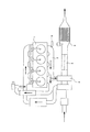
図4は、このうちの特許文献1に記載された構造を示している。この従来構造の場合、ディーゼルエンジン1から排気マニホールド2に排出されて、ノズル3から軽油を添加された排気を、過給器4、気化器5を介して排気浄化装置6に送り込む様にしている。この排気浄化装置6では、触媒の働きにより、窒素酸化物及びPMを無害化処理する。具体的には、Pt(或はCo、Pdの単体又は混合物)等の(酸化)触媒により、窒素酸化物中のNOを酸化剤としての機能の高いNO2 に変化させてから、このNO2 とPMとを反応させ{NO2 のO2 によりPM(C)を燃焼し}て、窒素酸化物及びPMを無害化処理する(N2 とCO2 とに変化させる)。この様な、排気浄化装置中での窒素酸化物及びPMの無害化処理の点に就いては、特許文献2、3に記載されている。 FIG. 4 shows the structure described in Patent Document 1 among them. In the case of this conventional structure, exhaust gas discharged from the diesel engine 1 to the exhaust manifold 2 and added with light oil from the nozzle 3 is sent to the exhaust purification device 6 via the supercharger 4 and the carburetor 5. . In the exhaust purification device 6, the nitrogen oxide and PM are rendered harmless by the action of the catalyst. Specifically, NO in nitrogen oxides is changed to NO 2 having a high function as an oxidizing agent by an (oxidation) catalyst such as Pt (or a simple substance or a mixture of Co and Pd), and then this NO 2 And PM are reacted {PM (C) is burned with NO 2 O 2 } to detoxify nitrogen oxides and PM (change them to N 2 and CO 2 ). Patent Documents 2 and 3 describe such detoxification treatment of nitrogen oxides and PM in the exhaust gas purification apparatus.
これら特許文献2、3等の記載から分かる様に、ディーゼルエンジンから排出される排気中に含まれる窒素酸化物及びPMを無害化処理する為には、排気の流れ方向に関して上流側に、上記NOをNO2 に変化させる為の酸化触媒を、同じく下流側にPMを捕捉する為の捕捉部を、それぞれ設ける事が必要である。この様な触媒と捕捉部とを備えた排気浄化装置として従来から一般的には、非特許文献1に記載されている様に、セラミック製のものが使用されていた。 As can be seen from the descriptions in Patent Documents 2 and 3, etc., in order to detoxify the nitrogen oxides and PM contained in the exhaust discharged from the diesel engine, the above NO is provided upstream in the exhaust flow direction. It is necessary to provide an oxidation catalyst for changing NO to NO 2 and a trapping portion for trapping PM on the downstream side. Conventionally, as described in Non-Patent Document 1, a ceramic-made exhaust purification device having such a catalyst and a trapping portion has been used.
即ち、上流側に配置したセラミック製の担体の表面にPt等の触媒を付着させ、下流側に、セラミック製で多孔質のフィルタを配置して、未燃焼のPMを捕捉する様にしている。この様にフィルタにより捕捉された未燃焼のPMは、上流側の触媒から送られて来るNO2 と反応(燃焼)する事でCO2 になり、大気中に放散される。尚、ディーゼルエンジンの排気中には、上記窒素酸化物やPMの他、炭化水素(HC)や一酸化炭素(CO)も含まれている。これらHCやCOに就いては、ガソリンエンジンの排気中にも含まれており、ガソリンエンジン用の排気浄化装置と同様の技術により、無害化処理できる。又、上記PMを燃焼させる為のフィルタ部分に、電熱ヒータを設け、このPMを加熱して燃焼する構造の排気浄化装置も、従来から知られている。 That is, a catalyst such as Pt is attached to the surface of a ceramic carrier disposed on the upstream side, and a ceramic porous filter is disposed on the downstream side to capture unburned PM. The unburned PM trapped by the filter in this way becomes CO 2 by reacting (burning) with NO 2 sent from the upstream catalyst, and is diffused into the atmosphere. The exhaust gas from the diesel engine contains hydrocarbon (HC) and carbon monoxide (CO) in addition to the nitrogen oxides and PM. These HC and CO are also contained in the exhaust of the gasoline engine, and can be rendered harmless by the same technology as the exhaust gas purification device for the gasoline engine. Further, an exhaust gas purification device having a structure in which an electric heater is provided in a filter portion for burning the PM and the PM is heated and burned is conventionally known.
PMを燃焼させる為のセラミック製のフィルタと触媒担体とを、排気の流れ方向に関して直列に、互いに独立して設けた構造の場合には、排気浄化装置の小型・軽量化並びに低コスト化を図りにくい。このうちの小型・軽量化を図りにくい理由は、互いに独立したフィルタと触媒担体とを設ける為である。又、低コスト化を図りにくい理由は、セラミック製のフィルタ自体の製造コストが嵩む事に加えて、薄肉で脆いセラミックが車両走行時の振動により破損するのを防止する為の緩衝構造が必要になる等の為である。 In the case of a structure in which a ceramic filter for burning PM and a catalyst carrier are provided independently in series in the exhaust flow direction, the exhaust purification device is reduced in size, weight and cost. Hateful. The reason why it is difficult to reduce the size and weight is to provide a filter and a catalyst carrier that are independent of each other. The reason why it is difficult to reduce the cost is that the manufacturing cost of the ceramic filter itself is increased, and a buffer structure is required to prevent the thin and brittle ceramic from being damaged by vibration during vehicle running. This is because it becomes.
一方、特許文献4、5には、不織布等を利用し、フィルタと触媒担体とを一体とした、ディーゼルエンジン用の排気浄化装置が記載されている。このうちの特許文献4には、ヒータと、セラミック製の不織布と、触媒層と、金網とを積層し、全体を波形に形成した排気浄化装置が記載されている。このうちの触媒層は、Niをベースとした金網の表面に、Pt等の、触媒となる金属粉末を分散させるとしている。又、特許文献5には、図5に示す様に、金属繊維製不織布により造った平板7と波板8とを交互に重ね合わせて巻回し、この金属繊維に触媒を担持した排気浄化装置が記載されている。
On the other hand, Patent Documents 4 and 5 describe an exhaust emission control device for a diesel engine that uses a nonwoven fabric or the like and integrates a filter and a catalyst carrier. Of these, Patent Document 4 describes an exhaust emission control device in which a heater, a ceramic nonwoven fabric, a catalyst layer, and a wire mesh are laminated to form an overall waveform. Of these, the catalyst layer is made to disperse a metal powder serving as a catalyst, such as Pt, on the surface of a metal mesh based on Ni. Further, as shown in FIG. 5, Patent Document 5 discloses an exhaust purification device in which
この様な特許文献4、5に記載された構造によれば、従来から実施されている様な、フィルタと触媒担体とを互いに独立して設けた構造に比べれば、排気浄化装置の小型・軽量化並びに低コスト化を図れるものと考えられるが、未だ改良の余地がある。例えば、特許文献4に記載された構造の場合には、排気の流通方向に関する厚さ寸法が小さい。又、特許文献5に記載された構造の場合には、排気の流通方向に関して直線的に連続する通路が存在する。この為、何れの構造の場合も、小型・軽量化を図ろうとした場合には、排気中に含まれるPMのうちで、フィルタに捕捉されず、無害化処理される事なく大気中に放散される割合が多くなるものと考えられる。 According to the structures described in Patent Documents 4 and 5 as described above, the exhaust purification device is smaller and lighter than the structure in which the filter and the catalyst carrier are provided independently of each other as conventionally performed. Although it is considered that the cost and cost can be reduced, there is still room for improvement. For example, in the case of the structure described in Patent Document 4, the thickness dimension in the exhaust flow direction is small. In the case of the structure described in Patent Document 5, there is a linearly continuous passage with respect to the flow direction of the exhaust. For this reason, in any structure, when trying to reduce the size and weight, PM contained in the exhaust gas is not trapped by the filter and diffused into the atmosphere without being detoxified. It is thought that the ratio will increase.
本発明は、上述の様な事情に鑑みて、小型・軽量化を図った場合でも、ディーゼルエンジンの排気中に含まれるPMの処理を効果的に行なえ、しかも低コストで造れる排気浄化装置を実現すべく発明したものである。 In view of the circumstances as described above, the present invention realizes an exhaust purification device that can effectively process PM contained in the exhaust of a diesel engine and can be manufactured at low cost even when it is reduced in size and weight. Invented as much as possible.
本発明の排気浄化装置とその製造方法のうち、請求項1に記載した排気浄化装置の発明は、金属線を編組して成る金網を、隣り合う金属線同士の間に排気が流通自在な隙間が存在する程度に圧縮して成る多孔質構造体を備える。そして、この多孔質構造体を構成する金属線のうち、少なくともこの排気の流通方向に関して上流寄り部分を構成する金属線の表面に、Pt等の触媒のコーティングを施している。上記多孔質構造体は、排気導入口と排気吐出口とを備えたケーシング内に収納して、排気浄化装置とする。
尚、本件の特許請求の範囲並びに明細書で言う編組としては、網代織り、綾織、メリヤス織り、平織り等を例示できる。このうちでもメリヤス織りした金網を使用する事が、優れた成形加工性を備え、密度のコントロールが容易である事から好ましい。
又、Pt等の触媒のコーティングは、金属線の表面のPtが強固に付着するものであれば、その手段は特に問わないが、一般的にはメッキにより行なう。
Of the exhaust purification device and the manufacturing method thereof according to the present invention, the invention of the exhaust purification device according to claim 1 is a metal mesh formed by braiding metal wires, and a gap through which exhaust gas can freely flow between adjacent metal wires. It is provided with a porous structure formed by compressing to the extent that exists. Of the metal wires constituting the porous structure, at least the surface of the metal wire constituting the upstream portion in the exhaust flow direction is coated with a catalyst such as Pt. The porous structure is housed in a casing having an exhaust introduction port and an exhaust discharge port to form an exhaust purification device.
In addition, examples of the braid as referred to in the claims and the specification of the present case include mesh weave, twill weave, knitted weave, and plain weave. Among these, it is preferable to use a knitted wire mesh because it has excellent moldability and can easily control the density.
The coating of the catalyst such as Pt is not particularly limited as long as Pt on the surface of the metal wire adheres firmly, but is generally performed by plating.
又、請求項3に記載した排気浄化装置の製造方法の発明は、金属線を編組して成り表面にPt等の触媒のコーティングを施した第一の金網と、この第一の金網とは別個に用意された、金属線を編組して成り表面にPt等の触媒のコーティングを施していない第二の金網とを組み合わせた状態で同時に圧縮して、この第二の金網と上記第一の金網とを一体的に結合する。そして、隣り合う金属線同士の間に排気が流通自在な隙間が存在して、排気の流通方向に関して上流寄り部分を構成する金属線の表面にPt等の触媒のコーティングを施された多孔質構造体とする。 According to a third aspect of the present invention, there is provided an exhaust purification device manufacturing method comprising: a first wire mesh braided with a metal wire and coated with a catalyst such as Pt on the surface; and the first wire mesh separately. The second wire mesh and the first wire mesh that are prepared by braiding the metal wire and compressing at the same time in combination with a second wire mesh that is not coated with a catalyst such as Pt on the surface. And are integrally coupled. A porous structure in which there is a gap through which exhaust can flow between adjacent metal wires, and the surface of the metal wire constituting the upstream portion in the exhaust flow direction is coated with a catalyst such as Pt. Let it be the body.
上述の様に構成する本発明によれば、小型・軽量で、ディーゼルエンジンの排気中に含まれるPMの無害化処理を効果的に行なえる排気浄化装置を、低コストで実現できる。
これらの効果は、金属線を編組して成る金網を圧縮して多孔質構造とすると共に、上流寄り部分に存在する金属線の表面にPt等の触媒のコーティングを施す事により図れる。即ち、上記多孔質構造は、内部に屈曲した多数の微細通路を有する為、排気の流れ方向に関する寸法を小さくしても、上記PMを効果的に捕捉し、無害化処理される事なく大気中に放散されるPMの量を僅少に抑えられる。
即ち、上記多孔質構造中に流入した排気は、直線的に進まずに屈曲して流れる(乱流となる)。従って、排気が直線的に進む、ハニカム状の触媒担体を使用した排気浄化装置に比べて、上記触媒と排気との接触面積を広くできる。この為、小型化しても、十分な排気浄化性能を確保できる。又、上記多孔質構造自体が緩衝作用を有する為、セラミック製のハニカム触媒担体を使用する場合の様に、別途緩衝材を設置する必要がなく、この面からも、排気浄化装置の小型・軽量化を図れる。
しかも、上記多孔質構造部分にPt等の触媒のコーティングを施す為、前述した従来構造の様に、フィルタと触媒担体とを互いに独立して設けた構造に比べ、容積効率を向上させて、この面からも小型・軽量化を図れる。
又、上記金網を圧縮して成る多孔質構造は、セラミック製の多孔質構造に比べ、量産効果を同じとした場合には低コストで造る事が可能で、しかも非常に優れた耐衝撃性を有する為、別途緩衝材を使用する必要がない。そして、緩衝材を省略する分、低コスト化と、多孔質構造と排気浄化装置を収納するケースの内面との間の空間を小さくする等による小型化とを図れる。
尚、上記金網を圧縮して成る多孔質構造の気孔率は、上記金属線の線径や、この金網を圧縮する程度(圧縮率)を変える事により、任意に調節できる。そして、上記気孔率を変える事で、上記多孔質構造によるPMの捕捉率、排気の流通に対する抵抗を調節できる。従って、上記気孔率は、排気浄化装置の設置スペースを勘案しつつ、必要な性能を確保する為に、設計的に定める。
According to the present invention configured as described above, it is possible to realize an exhaust purification device that is small and light and can effectively perform the detoxification process of PM contained in the exhaust of a diesel engine at low cost.
These effects can be achieved by compressing a wire mesh formed of braided metal wires to form a porous structure and coating the surface of the metal wires existing in the upstream portion with a catalyst such as Pt. That is, since the porous structure has a large number of fine passages bent inside, the PM can be captured effectively and detoxified without being detoxified even if the dimensions in the exhaust flow direction are reduced. The amount of PM released into the can be kept to a minimum.
That is, the exhaust gas that has flowed into the porous structure flows without being linearly bent and flows (becomes turbulent flow). Therefore, the contact area between the catalyst and the exhaust gas can be increased as compared with an exhaust gas purification device using a honeycomb-shaped catalyst carrier in which the exhaust gas advances linearly. For this reason, even if it reduces in size, sufficient exhaust gas purification performance is securable. In addition, since the porous structure itself has a buffering action, there is no need to install a separate buffer as in the case of using a ceramic honeycomb catalyst carrier. From this aspect as well, the exhaust purification device is compact and lightweight. Can be realized.
Moreover, since the porous structure portion is coated with a catalyst such as Pt, the volume efficiency is improved as compared with the structure in which the filter and the catalyst carrier are provided independently of each other as in the conventional structure described above. From the aspect, it is possible to reduce the size and weight.
In addition, the porous structure formed by compressing the wire mesh can be manufactured at a low cost when the mass production effect is the same as that of the ceramic porous structure, and has a very excellent impact resistance. Therefore, there is no need to use a separate cushioning material. Since the buffer material is omitted, the cost can be reduced and the size can be reduced by reducing the space between the porous structure and the inner surface of the case housing the exhaust purification device.
The porosity of the porous structure formed by compressing the wire mesh can be arbitrarily adjusted by changing the wire diameter of the metal wire and the degree to which the wire mesh is compressed (compression rate). By changing the porosity, it is possible to adjust the PM trapping rate by the porous structure and the resistance to the flow of exhaust gas. Therefore, the porosity is determined in terms of design in order to ensure the necessary performance while taking into account the installation space of the exhaust purification device.
本発明のうち、請求項1に記載した排気浄化装置に関する発明を実施する場合に好ましくは、請求項2に記載した様に、多孔質構造体を円筒状とし、排気が、一方の周面から他方の周面に向けて径方向に流れる構造とする。
この様に構成すれば、小型で車両の床下への設置が容易で、PMの無害化処理に関する性能が良好で、しかも排気の通過抵抗を低く抑えられる構造を実現できる。
即ち、車両の床下に排気浄化装置を設置する場合、長さ方向の寸法に関しては、車両の前後方向の寸法が十分にある事から、十分に確保できる。従って、円筒状の多孔質構造体の長さ寸法を確保する事により、排気の通過面積を広くして、上記通過抵抗を低く抑えられる。尚、この通過面積を広くする為には、車両の前後方向に直交する仮想平面に関する断面積を大きくする事も考えられるが、この断面積を広くした場合には、最下位置が低くなり、路面上の障害物に衝突し易くなる等、床下への設置が難しくなる可能性がある。上記請求項2に記載した構造を採用すれば、この様な問題を生じにくい。
Of the present invention, when the invention relating to the exhaust emission control device according to claim 1 is carried out, preferably, as described in claim 2, the porous structure is formed into a cylindrical shape, and the exhaust gas is discharged from one peripheral surface. It is set as the structure which flows to radial direction toward the other surrounding surface.
If comprised in this way, the structure which is small and can be easily installed under the floor of the vehicle, has good performance regarding the detoxification process of PM, and can suppress the exhaust passage resistance to a low level.
That is, when the exhaust emission control device is installed under the floor of the vehicle, the longitudinal dimension can be sufficiently secured because the longitudinal dimension of the vehicle is sufficient. Therefore, by ensuring the length of the cylindrical porous structure, the passage area of the exhaust can be widened and the passage resistance can be kept low. In order to widen this passage area, it is possible to increase the cross-sectional area related to the virtual plane orthogonal to the longitudinal direction of the vehicle, but when this cross-sectional area is widened, the lowest position becomes lower, Installation under the floor may be difficult, for example, it may be easy to collide with obstacles on the road surface. If the structure described in claim 2 is adopted, such a problem is hardly caused.
又、請求項3に記載した排気浄化装置の製造方法に関する発明を実施する場合に好ましくは、請求項4に記載した様に、第一の金網を、予め表面にPt等の触媒のコーティングを施した金属線を編組する事により造る。
Pt等の触媒のコーティングは、金属線を編組して上記第一の金網とした後に行なう事もできるが、この場合には、コーティングの対象物(第一の金網)が大きくなり、メッキ槽等のコーティングの為の設備が大きくなる。又、金属線同士の接触部にPt等の触媒が十分に付着しない可能性もある。
これに対して、上記請求項4に記載した様に、予め表面にPt等の触媒のコーティングを施した金属線を編組して上記第一の金網とすれば、コーティングの対象物(金属線)が小さい為、メッキ槽等のコーティングの為の設備を小さくできる。又、金属線同士の接触部にもPt等の触媒が十分に付着する為、その分、排気浄化装置の性能向上を図れる。
Further, when carrying out the invention relating to the method for manufacturing an exhaust emission control device described in claim 3, preferably, as described in claim 4, the first metal mesh is coated with a catalyst such as Pt on the surface in advance. It is made by braiding metal wires.
The coating of the catalyst such as Pt can be performed after the metal wire is braided to form the first wire mesh. However, in this case, an object to be coated (first wire mesh) becomes large, and a plating tank or the like is formed. The equipment for coating is increased. Further, there is a possibility that a catalyst such as Pt does not sufficiently adhere to the contact portion between the metal wires.
On the other hand, as described in claim 4 above, if the metal wire previously coated with a catalyst such as Pt is braided to form the first wire mesh, the object to be coated (metal wire) Because of the small size, the equipment for coating such as a plating tank can be reduced. Further, since the catalyst such as Pt is sufficiently adhered to the contact portion between the metal wires, the performance of the exhaust gas purification device can be improved accordingly.
又、上記請求項3或は請求項4に記載した排気浄化装置の製造方法に関する発明を実施する場合に好ましくは、請求項5に記載した様に、第一、第二の金網を構成する金属線をステンレス鋼製とする。そして、このうちの第一の金網を構成するステンレス鋼製の金属線の表面にNiメッキを施した後、若しくはNiメッキの表面に更にCrメッキを施した後、このNiメッキ若しくはCrメッキの表面に、触媒であるPtのコーティングを施す。 Preferably, when carrying out the invention relating to the method for manufacturing an exhaust emission control device according to claim 3 or 4, the metal constituting the first and second wire meshes as described in claim 5. The wire is made of stainless steel. And after performing Ni plating on the surface of the metal wire made of stainless steel constituting the first wire mesh of these, or after further applying Cr plating to the surface of Ni plating, the surface of this Ni plating or Cr plating Then, a coating of Pt as a catalyst is applied.
ステンレス鋼製の金属線は優れた耐熱性(耐酸化性)を有する為、窒素酸化物やPMの処理に伴う温度上昇に拘らず、優れた耐久性を得られる。即ち、本発明を実施する場合、排気の流通に対する抵抗を低く抑える為に多孔質構造体の気孔率を高くし、しかも排気と触媒であるPtとの接触機会を増やすべく、この多孔質構造体内部の微細流路を複雑に(屈曲する回数を多く)する為には、上記金属線の線径を小さく(細く)する必要がある。そして、この線径を小さくした場合には、この金属線として、優れた耐熱性を有するものを使用する必要がある。単に耐熱性のみを満たせば良いのであれば、上記金属線をW、Ti製にする事も考えられるが、コスト並びに(圧縮して多孔質構造体とする場合の)塑性変形性を考慮した場合には採用できない。これに対して、上記金属線をステンレス鋼製とすれば、耐熱性、低コスト性、加工性の何れも、十分に実用可能なレベルで得られる。 Since the stainless steel metal wire has excellent heat resistance (oxidation resistance), excellent durability can be obtained regardless of the temperature rise associated with the treatment of nitrogen oxides and PM. That is, when practicing the present invention, in order to increase the porosity of the porous structure in order to keep the resistance to the flow of exhaust gas low, and to increase the chance of contact between the exhaust gas and the catalyst Pt, the porous structure In order to complicate the internal fine flow path (increase the number of times of bending), it is necessary to make the diameter of the metal wire small (thin). And when this wire diameter is made small, it is necessary to use what has the outstanding heat resistance as this metal wire. If it is sufficient to satisfy only heat resistance, the metal wire may be made of W or Ti. However, in consideration of cost and plastic deformability (when compressed into a porous structure) It cannot be adopted. On the other hand, if the metal wire is made of stainless steel, all of heat resistance, low cost, and workability can be obtained at a sufficiently practical level.
但し、ステンレス鋼製の金属線を使用した場合には、そのままではこの金属線の表面にコーティング(メッキ)したPtの結合強度を十分に得られない。これに対して、上述の様にステンレス鋼製の金属線の表面にNiメッキを施した後、このNiメッキの表面にPtコーティングを施せば、この金属線に対するPtの結合強度を十分に確保できる。即ち、ステンレス鋼に対するNiメッキの結合強度は十分に高くでき、このNiメッキに対するPtのコーティング(メッキ)層の結合強度も十分に高くできる。この様に、上記Niメッキがバインダーとして機能させる事により、上記ステンレス鋼製の金属線に対するPtのコーティング層の結合強度が高くなる。この結果、第一の金網の表面に存在するPtによる排気浄化作用を、長期間に亙って十分に発揮できる。 However, when a stainless steel metal wire is used, the bond strength of Pt coated (plated) on the surface of the metal wire cannot be obtained as it is. On the other hand, if the surface of the metal wire made of stainless steel is plated with Ni as described above and then the surface of this Ni plating is coated with Pt, the bond strength of Pt to the metal wire can be sufficiently secured. . That is, the bond strength of Ni plating to stainless steel can be made sufficiently high, and the bond strength of the Pt coating (plating) layer to this Ni plating can also be made sufficiently high. Thus, the Ni plating functions as a binder, so that the bonding strength of the Pt coating layer to the stainless steel metal wire is increased. As a result, the exhaust purification action by Pt existing on the surface of the first wire mesh can be sufficiently exhibited over a long period of time.
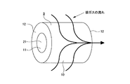
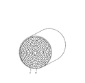
図1〜2は、請求項1、2に対応する、本発明の実施例1を示している。本実施例の場合には、SUS316L等のステンレス鋼製の金属線を、例えばメリヤス編み等で編組して成る金網を、隣り合う金属線同士の間に排気が流通自在な隙間が存在する程度に軽く圧縮し、全体が円筒状の多孔質構造体9としている。本実施例の場合、この多孔質構造体9を構成する、上記ステンレス鋼製の金属線の全体に、Niメッキを介してPtメッキを施している。これらNiメッキ及びPtメッキは、金網を編組する以前の、金属線の状態で施している。
1 and 2 show a first embodiment of the present invention corresponding to claims 1 and 2. In the case of the present embodiment, a metal mesh formed by braiding stainless steel metal wires such as SUS316L, for example, by knitting, etc., to the extent that there is a gap through which exhaust can freely flow between adjacent metal wires. The
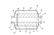
上述の様な多孔質構造体9は、図2に示す様に、排気導入口13と排気吐出口14とを備えたケーシング15内に収納して、排気浄化装置16とする。この場合に、上記多孔質構造体9をこのケーシング15内に、この多孔質構造体9が上記排気導入口13と上記排気吐出口14とを仕切る状態で設置する。具体的には、この排気導入口13に通じる空間を上記多孔質構造体9の外周面10にのみ対向させ、この多孔質構造体9の内周面11及び軸方向両端面12、12には対向させない。又、上記排気吐出口14に通じる空間を上記多孔質構造体9の内周面11にのみ対向させ、この多孔質構造体9の外周面10及び軸方向両端面12、12には対向させない。
The
この為に、この多孔質構造体9の軸方向両端面12、12は、上記ケーシング15内に設けた段部17a、17b等に突き当てる。又、本実施例の場合には、このケーシング15の内周面を、円周方向に関する断面形状を波形にする事により、上記多孔質構造体9の外周面10を抑えつつ、この多孔質構造体9の外周面10側に排気を導入できる様にしている。即ち、本実施例の場合には、上記ケーシング15の内周面に、上記多孔質構造体9の軸方向(図2の左右方向)に長い複数の凹溝18、18を、円周方向に関して間欠的に形成している。上記多孔質構造体9の外周面10は、これら各凹溝18、18同士の間に存在する土手状部により抑えられて、上記ケーシング15内でのがたつきを防止される。又、上記各凹溝18、18の一端は、それぞれ上記排気導入口13に通じさせる。更に、これら各凹溝18、18の一端と排気導入口13とを連続させる排気流路19、19部分から、排気が短絡する事を防止する為に、上記多孔質構造体9のうちで上記排気導入口13に対向する端面12は、円板状の塞ぎ板20により塞いでいる。
For this purpose, both axial end surfaces 12 and 12 of the
上述の様に構成する本実施例の排気浄化装置16の場合、上記排気導入口13から上記ケーシング15内に導入された排気は、上記各凹溝18、18を通じて上記多孔質構造体9の周囲に導かれる。次いでこの排気は、この多孔質構造体9内を、図1に矢印で示す様に、径方向外側から内側に流れる。この間に排気中に含まれる有害成分が、前記金属線の表面にコーティングされたPtの働きにより無害化処理される。具体的には、Ptが触媒として働く事で、排気中の窒素酸化物のうちのNOをNO2 に変化させ、このNO2 とPMとを反応させて、窒素酸化物及びPMを無害化処理する(N2 とCO2 とに変化させる)。
In the case of the exhaust
本発明の場合には、上記多孔質構造体9の内部に、屈曲した複雑な微細流路が多数存在する為、排気がこの多孔質構造体9内に止まっている時間は長く、この排気とPtとの接触は効果的に行なわれる。又、PMの捕捉も効果的に行なわれる。この為、上記排気の無害化処理の効率が良好になる。上述の様にして無害化処理された排気は、上記多孔質構造体9の中心孔21から、前記排気吐出口14を通じて排出される。尚、本発明の特徴は、上記多孔質構造体9部分にあり、ケーシング15の構造は特に問わない。
In the case of the present invention, since there are a large number of bent and complicated fine flow paths inside the
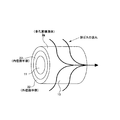
図3は、請求項1〜5に対応する、本発明の実施例2を示している。本実施例の場合には、多孔質構造体9aの外径側半部22を構成する金属線の表面にのみPtコーティングを施し、内径側半部23を構成する金属線の表面にはPtコーティングを施していない。この様に、外径側半部22と内径側半部23との性状を異ならせた、上記多孔質構造体9aを造る場合には、先ず、金属線を編組して成り表面にPtコーティングを施した第一の金網と、この第一の金網とは別個に用意された、金属線を編組して成り表面にPtコーティングを施していない第二の金網とを、上記第一の金網の内径側にこの第二の金網を挿入した状態に組み合わせる。次いで、これら両金網を同時に圧縮して、これら両金網同士を一体的に結合する。
この様な本実施例の場合、機能上はPtメッキを施す必要がない内径側半部23のPtメッキを省略する分、高価なPtの使用量を抑えて、その分のコスト低減を図れる。その他の構成及び作用は、上述した実施例1と同様であるから、重複する説明は省略する。
FIG. 3 shows Embodiment 2 of the present invention corresponding to claims 1 to 5. In the case of the present embodiment, Pt coating is applied only to the surface of the metal wire constituting the outer diameter side half 22 of the porous structure 9a, and Pt coating is applied to the surface of the metal wire constituting the inner
In the case of this embodiment, the amount of expensive Pt used can be suppressed and the cost can be reduced by omitting the Pt plating of the inner diameter
1 ディーゼルエンジン
2 排気マニホールド
3 ノズル
4 過給器
5 気化器
6 排気浄化装置
7 平板
8 波板
9、9a 多孔質構造体
10 外周面
11 内周面
12 端面
13 排気導入口
14 排気吐出口
15 ケーシング
16 排気浄化装置
17a、17b 段部
18 凹溝
19 排気流路
20 塞ぎ板
21 中心孔
22 外径側半部
23 内径側半部
DESCRIPTION OF SYMBOLS 1 Diesel engine 2 Exhaust manifold 3 Nozzle 4 Supercharger 5 Vaporizer 6
Claims (5)
Priority Applications (1)
| Application Number | Priority Date | Filing Date | Title |
|---|---|---|---|
| JP2004116310A JP2005299486A (en) | 2004-04-12 | 2004-04-12 | Exhaust emission control device and manufacturing method thereof |
Applications Claiming Priority (1)
| Application Number | Priority Date | Filing Date | Title |
|---|---|---|---|
| JP2004116310A JP2005299486A (en) | 2004-04-12 | 2004-04-12 | Exhaust emission control device and manufacturing method thereof |
Publications (1)
| Publication Number | Publication Date |
|---|---|
| JP2005299486A true JP2005299486A (en) | 2005-10-27 |
Family
ID=35331346
Family Applications (1)
| Application Number | Title | Priority Date | Filing Date |
|---|---|---|---|
| JP2004116310A Pending JP2005299486A (en) | 2004-04-12 | 2004-04-12 | Exhaust emission control device and manufacturing method thereof |
Country Status (1)
| Country | Link |
|---|---|
| JP (1) | JP2005299486A (en) |
Cited By (1)
| Publication number | Priority date | Publication date | Assignee | Title |
|---|---|---|---|---|
| JP5704548B1 (en) * | 2014-04-24 | 2015-04-22 | 株式会社深井製作所 | Catalyzer element and catalyzer |
-
2004
- 2004-04-12 JP JP2004116310A patent/JP2005299486A/en active Pending
Cited By (1)
| Publication number | Priority date | Publication date | Assignee | Title |
|---|---|---|---|---|
| JP5704548B1 (en) * | 2014-04-24 | 2015-04-22 | 株式会社深井製作所 | Catalyzer element and catalyzer |
Similar Documents
| Publication | Publication Date | Title |
|---|---|---|
| US5908480A (en) | Particulate trap for diesel engine | |
| CN101801499B (en) | Tuning particulate filter performance through selective plugging and use of multiple particulate filters to reduce emissions and improve thermal robustness | |
| JP6436615B2 (en) | Partial filter substrate including SCR catalyst, exhaust treatment system, and engine exhaust treatment method | |
| CN101460718B (en) | Off-line filter with improved filter efficiency | |
| JP2005507476A (en) | Open-type particle filter with heating device | |
| US10107162B2 (en) | Catalyst subassembly, device comprising same for purifying exhaust gases from an internal combustion engine, modular system for the subassembly, and method for manufacturing the subassembly | |
| CN105814292A (en) | Exhaust gas purification material | |
| CN101384798A (en) | Muffler assembly with metal catalyst inside | |
| US7247185B2 (en) | Device for treatment of a gas flow | |
| JP3371427B2 (en) | Exhaust purification catalyst for diesel engine | |
| JPWO1998006492A1 (en) | Diesel engine exhaust purification catalyst | |
| KR101030591B1 (en) | Apparatus for separating particles contained in exhaust gases of internal combustion engines | |
| CN1195940C (en) | Device for purifying waste gas of diesel motor | |
| US8137637B2 (en) | Particulate filter and method of making | |
| CN100478548C (en) | Diesel soot particulate filter medium | |
| JP3922076B2 (en) | Particulate filter | |
| JP2005299486A (en) | Exhaust emission control device and manufacturing method thereof | |
| JP4413366B2 (en) | Exhaust gas purification catalyst | |
| KR101150325B1 (en) | An exhaust gas reducing assembly for a vehicles which is possessed of duplex catalyst portion | |
| WO2010128570A1 (en) | Exhaust gas purifying device | |
| WO2017150582A1 (en) | Exhaust gas purification device for internal combustion engine | |
| KR100914279B1 (en) | Catalyst for purifying exhaust gases and process for producing the same | |
| WO2021079556A1 (en) | Muffler and honeycomb structure for muffler | |
| CN100422516C (en) | Exhaust gas converter for internal combustion engine | |
| JP2006102742A (en) | Filter assembly for exhaust treatment apparatus |
Legal Events
| Date | Code | Title | Description |
|---|---|---|---|
| A621 | Written request for application examination |
Free format text: JAPANESE INTERMEDIATE CODE: A621 Effective date: 20061227 |
|
| RD04 | Notification of resignation of power of attorney |
Free format text: JAPANESE INTERMEDIATE CODE: A7424 Effective date: 20070406 |
|
| A977 | Report on retrieval |
Free format text: JAPANESE INTERMEDIATE CODE: A971007 Effective date: 20090812 |
|
| A131 | Notification of reasons for refusal |
Free format text: JAPANESE INTERMEDIATE CODE: A131 Effective date: 20090825 |
|
| A02 | Decision of refusal |
Free format text: JAPANESE INTERMEDIATE CODE: A02 Effective date: 20100107 |