JP2005299621A - Wind speed increasing device and wind power generation device using the same - Google Patents
Wind speed increasing device and wind power generation device using the same Download PDFInfo
- Publication number
- JP2005299621A JP2005299621A JP2004141687A JP2004141687A JP2005299621A JP 2005299621 A JP2005299621 A JP 2005299621A JP 2004141687 A JP2004141687 A JP 2004141687A JP 2004141687 A JP2004141687 A JP 2004141687A JP 2005299621 A JP2005299621 A JP 2005299621A
- Authority
- JP
- Japan
- Prior art keywords
- wind
- speed increasing
- increasing device
- power generation
- speed
- Prior art date
- Legal status (The legal status is an assumption and is not a legal conclusion. Google has not performed a legal analysis and makes no representation as to the accuracy of the status listed.)
- Pending
Links
- 238000010248 power generation Methods 0.000 title claims abstract description 8
- 230000000694 effects Effects 0.000 claims abstract description 4
- 238000010276 construction Methods 0.000 abstract 1
- 230000005611 electricity Effects 0.000 description 3
- 241001465754 Metazoa Species 0.000 description 1
- 230000005484 gravity Effects 0.000 description 1
Images
Classifications
-
- Y—GENERAL TAGGING OF NEW TECHNOLOGICAL DEVELOPMENTS; GENERAL TAGGING OF CROSS-SECTIONAL TECHNOLOGIES SPANNING OVER SEVERAL SECTIONS OF THE IPC; TECHNICAL SUBJECTS COVERED BY FORMER USPC CROSS-REFERENCE ART COLLECTIONS [XRACs] AND DIGESTS
- Y02—TECHNOLOGIES OR APPLICATIONS FOR MITIGATION OR ADAPTATION AGAINST CLIMATE CHANGE
- Y02B—CLIMATE CHANGE MITIGATION TECHNOLOGIES RELATED TO BUILDINGS, e.g. HOUSING, HOUSE APPLIANCES OR RELATED END-USER APPLICATIONS
- Y02B10/00—Integration of renewable energy sources in buildings
- Y02B10/30—Wind power
-
- Y—GENERAL TAGGING OF NEW TECHNOLOGICAL DEVELOPMENTS; GENERAL TAGGING OF CROSS-SECTIONAL TECHNOLOGIES SPANNING OVER SEVERAL SECTIONS OF THE IPC; TECHNICAL SUBJECTS COVERED BY FORMER USPC CROSS-REFERENCE ART COLLECTIONS [XRACs] AND DIGESTS
- Y02—TECHNOLOGIES OR APPLICATIONS FOR MITIGATION OR ADAPTATION AGAINST CLIMATE CHANGE
- Y02E—REDUCTION OF GREENHOUSE GAS [GHG] EMISSIONS, RELATED TO ENERGY GENERATION, TRANSMISSION OR DISTRIBUTION
- Y02E10/00—Energy generation through renewable energy sources
- Y02E10/70—Wind energy
- Y02E10/74—Wind turbines with rotation axis perpendicular to the wind direction
Landscapes
- Wind Motors (AREA)
Abstract
Description
この発明は、東西南北のどの方向からの風にも対応し、さらに風集性のある風通路を用いることによって、風の流入効率が向上し増速することで風車の回転を増すことが可能な、風増速装置及びこれを用いた風力発電装置に関するものである。 This invention can respond to wind from any direction from east, west, south, and north, and by using a wind path with high wind collection, it is possible to increase the rotation speed of the windmill by improving and increasing the wind inflow efficiency. The present invention relates to a wind speed increasing device and a wind power generator using the same.
従来、特開2003−328922号の公報に示されるように、一定の風に対応し、風の流れを増速する風増装置を用いて発電する風力発電装置というものがあった。 Conventionally, as disclosed in Japanese Patent Application Laid-Open No. 2003-328922, there has been a wind power generator that generates electricity using a wind-intensifier that responds to a constant wind and accelerates the flow of the wind.
それには、次のような問題点があった。
(イ)決まった方向の風の流入にしか対応できず、風の利用効率が低かった。
(ロ)風の変化に対応し、風の利用効率を高めようとすれば装置が大型化した。
本発明は、これらの問題点を解決するために成されたものである。There were the following problems.
(B) It was only possible to respond to wind inflows in a specific direction, and wind utilization efficiency was low.
(B) In response to changes in the wind, the size of the device was increased if it was attempted to increase the efficiency of wind utilization.
The present invention has been made to solve these problems.
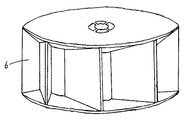
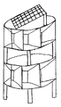
風通路入口から風通路出口に向かって上下左右の壁が縮小する風通路が、風を集める効果を及ぼし、増速させると共に、風車羽根に風が的確に当たるように流入案内する風増速装置を設ける。筒部材の側面に間隔をもって開けた複数の穴に、あらゆる方角の風を流入案内する風通路を取り付けると共に、風を逃す風排気孔を上部に設置した風増速装置を設ける。本発明は、以上の構成からなる風増速装置と垂直軸型風力発電装置を用いた発電装置である。 The wind passage where the top, bottom, left and right walls shrink from the wind passage entrance to the wind passage exit has the effect of collecting wind and speeding up, and a wind speed increasing device that guides inflow so that the wind hits the windmill blade accurately Provide. A wind speed increasing device is provided in which a wind passage for introducing and guiding wind in all directions is attached to a plurality of holes formed at intervals in the side surface of the cylindrical member, and a wind exhaust hole for allowing the wind to escape is installed in the upper part. The present invention is a power generator using the wind speed increasing device and the vertical axis wind power generator configured as described above.
以下、本発明の実施の形態について説明する。
(イ)風の流れを円滑に風車羽根5aに当てるための筒部材1に、かつ東西南北のどの方向からでも風を送り込めるように、筒部材1の側壁に等間隔を持たせ複数の適当な大きさの孔1aを設ける。
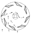
(ロ)風を集め、流れを強くするため、風通路入口から風通路出口に向かって上面2aと下面2bを縮小すると共に、正面から来る風を時計回りに変えて風車羽根5aに当たりやすくするため、風通路入口から風通路出口に向かって右側面2cと左側面2dが縮小し、さらに左側面2dより右側面2cの縮小が大きく、風通路出口は風通路入口より左寄りになる風通路2を設ける。
(ハ)風通路2で集め増速した風を風車羽根5aまで導くために、風通路2の風通路出口の開口部を筒部材の孔1aに周設するように設ける。
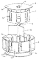
(ニ)風通路2で集め増速した風を、風通路出口や風車回転中に逃がし難くするため、円盤部材3の上壁3aと下壁3bを周設した風通路2と筒部材1に覆設するように設ける。
(ホ)筒部材1の中の弱くなった風を排出するために、円盤上壁3aの中心付近に複数の適当な大きさの風排気孔4を設ける。
(ヘ)風増速装置6の中の中心部に、等間隔に複数の羽根を備えた発電用の垂直軸型風車5を設ける。
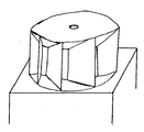
本発明は、以上のような構造でこれを使用するときは、本発明を建築物に設置する構造で、風の力で発電を起こし、発電した電力を建築物内で利用し、また発電した電力を需要のある地域社会に提供するものである。Embodiments of the present invention will be described below.
(A) A plurality of appropriate values are provided by providing equal spacing to the side wall of the
(B) In order to collect wind and strengthen the flow, the upper surface 2a and the lower surface 2b are reduced from the wind passage inlet toward the wind passage outlet, and the wind coming from the front is changed clockwise to make it easier to hit the windmill blade 5a. The
(C) In order to guide the wind collected and accelerated in the
(D) In order to make it difficult for the wind collected and accelerated in the
(E) In order to discharge the weakened wind in the
(F) A vertical
When the present invention is used in a structure as described above, the present invention is installed in a building. Electricity is generated by wind force, and the generated electric power is used in the building. It provides electricity to local communities in demand.
建物の屋上や住宅の尾根に取り付け可能である。さらに、道路や橋の街路灯、公園や一般家庭の庭の屋外灯にも取り付けが可能である。
また、垂直方向に複数重ねることで発電量を増すことができる。さらに、太陽光発電装置を重ねることもできる。
また、風車本体を風増速装置で覆うことで人や動物が誤って直接風車羽根に触れることがなく安全である。
また、垂直軸型風車であるため重心が低く景観の印象が目立ち難いという利点があるため、ウインドファームとしても、道路や近隣民家に対する圧迫感等を回避することができ、配置が可能である。
また、電力供給を目的とした事業用の風力発電装置として地域社会に寄与することもできる。It can be attached to the roof of a building or the ridge of a house. Furthermore, it can be installed on street lights on roads and bridges, and outdoor lights in parks and general household gardens.
Moreover, the amount of power generation can be increased by stacking a plurality in the vertical direction. Furthermore, a solar power generation device can be stacked.
Further, by covering the windmill body with the wind speed increasing device, it is safe for humans and animals not to touch the windmill blades by mistake.
Moreover, since it is a vertical axis type windmill, there is an advantage that the center of gravity is low and the impression of the landscape is not conspicuous. Therefore, even a wind farm can avoid a feeling of pressure on roads and neighboring private houses, and can be arranged.
It can also contribute to the local community as a business-use wind power generator for power supply.
(1)筒部材
(2)風通路
(3)円盤部材
(4)風排気孔
(5)垂直軸型風車
(6)風増速装置(1) Cylindrical member (2) Wind passage (3) Disk member (4) Wind exhaust hole (5) Vertical axis wind turbine (6) Wind speed increasing device
Claims (3)
Priority Applications (1)
| Application Number | Priority Date | Filing Date | Title |
|---|---|---|---|
| JP2004141687A JP2005299621A (en) | 2004-04-08 | 2004-04-08 | Wind speed increasing device and wind power generation device using the same |
Applications Claiming Priority (1)
| Application Number | Priority Date | Filing Date | Title |
|---|---|---|---|
| JP2004141687A JP2005299621A (en) | 2004-04-08 | 2004-04-08 | Wind speed increasing device and wind power generation device using the same |
Publications (1)
| Publication Number | Publication Date |
|---|---|
| JP2005299621A true JP2005299621A (en) | 2005-10-27 |
Family
ID=35331454
Family Applications (1)
| Application Number | Title | Priority Date | Filing Date |
|---|---|---|---|
| JP2004141687A Pending JP2005299621A (en) | 2004-04-08 | 2004-04-08 | Wind speed increasing device and wind power generation device using the same |
Country Status (1)
| Country | Link |
|---|---|
| JP (1) | JP2005299621A (en) |
Cited By (9)
| Publication number | Priority date | Publication date | Assignee | Title |
|---|---|---|---|---|
| WO2008029967A1 (en) * | 2006-09-05 | 2008-03-13 | Irwindpower Co., Ltd | Advanced wind power system |
| WO2010098656A3 (en) * | 2009-02-24 | 2011-01-27 | Universiti Malaya | Wind, solar and rain harvester |
| WO2011017508A3 (en) * | 2009-08-05 | 2011-06-30 | Pezaris Constantine D | Omnidirectional vertical-axis turbine |
| WO2011059760A3 (en) * | 2009-10-29 | 2011-09-09 | The Green Electric Company, A Massachusetts Corporation | Wind energy system |
| WO2011084432A3 (en) * | 2009-12-16 | 2011-09-09 | Percy Kawas | Method and apparatus for wind energy system |
| WO2011086406A3 (en) * | 2010-01-18 | 2011-12-29 | Treecube S.R.L. | Fitting for a wind turbine, wind turbine with such a fitting and method for improving the efficiency of such a wind turbine |
| WO2015004588A1 (en) | 2013-07-12 | 2015-01-15 | Treecube S.R.L. | Vertical axis wind turbine |
| WO2020171291A1 (en) * | 2019-02-19 | 2020-08-27 | 윤성현 | Wind power generation apparatus |
| WO2023239248A1 (en) * | 2022-06-06 | 2023-12-14 | Komarow Tomasz | Amplifier of wind power in vertical axis wind turbine |
-
2004
- 2004-04-08 JP JP2004141687A patent/JP2005299621A/en active Pending
Cited By (12)
| Publication number | Priority date | Publication date | Assignee | Title |
|---|---|---|---|---|
| WO2008029967A1 (en) * | 2006-09-05 | 2008-03-13 | Irwindpower Co., Ltd | Advanced wind power system |
| WO2010098656A3 (en) * | 2009-02-24 | 2011-01-27 | Universiti Malaya | Wind, solar and rain harvester |
| WO2011017508A3 (en) * | 2009-08-05 | 2011-06-30 | Pezaris Constantine D | Omnidirectional vertical-axis turbine |
| US8128337B2 (en) | 2009-08-05 | 2012-03-06 | Constantine D Pezaris | Omnidirectional vertical-axis wind turbine |
| WO2011059760A3 (en) * | 2009-10-29 | 2011-09-09 | The Green Electric Company, A Massachusetts Corporation | Wind energy system |
| US8167533B2 (en) | 2009-10-29 | 2012-05-01 | The Green Electric Company | Wind energy system |
| WO2011084432A3 (en) * | 2009-12-16 | 2011-09-09 | Percy Kawas | Method and apparatus for wind energy system |
| WO2011086406A3 (en) * | 2010-01-18 | 2011-12-29 | Treecube S.R.L. | Fitting for a wind turbine, wind turbine with such a fitting and method for improving the efficiency of such a wind turbine |
| WO2015004588A1 (en) | 2013-07-12 | 2015-01-15 | Treecube S.R.L. | Vertical axis wind turbine |
| JP2016524094A (en) * | 2013-07-12 | 2016-08-12 | ツリーキューブ エス.アール.エル. | Vertical axis wind turbine |
| WO2020171291A1 (en) * | 2019-02-19 | 2020-08-27 | 윤성현 | Wind power generation apparatus |
| WO2023239248A1 (en) * | 2022-06-06 | 2023-12-14 | Komarow Tomasz | Amplifier of wind power in vertical axis wind turbine |
Similar Documents
| Publication | Publication Date | Title |
|---|---|---|
| US8961103B1 (en) | Vertical axis wind turbine with axial flow rotor | |
| JP5449060B2 (en) | Wind power generator | |
| US8063502B1 (en) | Shrouded wind turbine with dual coaxial airflow passageways | |
| US20120175883A1 (en) | Hollow rotor core for generating a vortex in a wind turbine | |
| WO2016023351A1 (en) | All-directional flow-guide shaftless wind-driven generator | |
| JP2010065676A (en) | Wind power energy system, wind power energy conversion system, and wind tunnel module | |
| JP2005299621A (en) | Wind speed increasing device and wind power generation device using the same | |
| KR20110084023A (en) | Wind Turbine Using Vertical Updraft of Wind Collector Structure | |
| JP3153015U (en) | Wind power generation system | |
| WO2006123951A1 (en) | A wind turbine | |
| EP2264309A2 (en) | Wind turbine for an omnidirectional flow | |
| US20120098262A1 (en) | Energy production device from an omnidirectional Bi-axial flow | |
| US20220136482A1 (en) | Improvements to a helical fan/pump/propeeler/trubine | |
| TWI833230B (en) | Improvements in wind turbines | |
| US11629692B1 (en) | Vertical spiral wind turbine | |
| EP2054619A1 (en) | Omni-directional wind power station | |
| JP2006214302A (en) | Wind turbine device | |
| CN201358891Y (en) | Roof wind-force power-generation device | |
| CN101798988A (en) | Method and device for improving performance of resistance-type vertical axis wind turbine | |
| CN205936974U (en) | It can formula wind generating set to catch | |
| JP2013160115A (en) | Wind power generator | |
| CN101761450A (en) | Combined type wind power generation device | |
| SG177024A1 (en) | Vertical-axis wind-turbine with stacked propellers and an inground road installation | |
| JP2005220893A (en) | Wind speed increasing device with wind direction snake attached to omnidirectional vertical wind turbine | |
| JPS5830485A (en) | Wind power generation method |