JP2005299700A - Pipe fitting - Google Patents
Pipe fitting Download PDFInfo
- Publication number
- JP2005299700A JP2005299700A JP2004112268A JP2004112268A JP2005299700A JP 2005299700 A JP2005299700 A JP 2005299700A JP 2004112268 A JP2004112268 A JP 2004112268A JP 2004112268 A JP2004112268 A JP 2004112268A JP 2005299700 A JP2005299700 A JP 2005299700A
- Authority
- JP
- Japan
- Prior art keywords
- pipe
- pipe joint
- main body
- tube
- impact
- Prior art date
- Legal status (The legal status is an assumption and is not a legal conclusion. Google has not performed a legal analysis and makes no representation as to the accuracy of the status listed.)
- Pending
Links
Images
Classifications
-
- F—MECHANICAL ENGINEERING; LIGHTING; HEATING; WEAPONS; BLASTING
- F16—ENGINEERING ELEMENTS AND UNITS; GENERAL MEASURES FOR PRODUCING AND MAINTAINING EFFECTIVE FUNCTIONING OF MACHINES OR INSTALLATIONS; THERMAL INSULATION IN GENERAL
- F16L—PIPES; JOINTS OR FITTINGS FOR PIPES; SUPPORTS FOR PIPES, CABLES OR PROTECTIVE TUBING; MEANS FOR THERMAL INSULATION IN GENERAL
- F16L37/00—Couplings of the quick-acting type
- F16L37/08—Couplings of the quick-acting type in which the connection between abutting or axially overlapping ends is maintained by locking members
- F16L37/12—Couplings of the quick-acting type in which the connection between abutting or axially overlapping ends is maintained by locking members using hooks, pawls, or other movable or insertable locking members
- F16L37/14—Joints secured by inserting between mating surfaces an element, e.g. a piece of wire, a pin, a chain
- F16L37/142—Joints secured by inserting between mating surfaces an element, e.g. a piece of wire, a pin, a chain where the securing element is inserted tangentially
- F16L37/144—Joints secured by inserting between mating surfaces an element, e.g. a piece of wire, a pin, a chain where the securing element is inserted tangentially the securing element being U-shaped
Landscapes
- Engineering & Computer Science (AREA)
- General Engineering & Computer Science (AREA)
- Mechanical Engineering (AREA)
- Branch Pipes, Bends, And The Like (AREA)
- Protection Of Pipes Against Damage, Friction, And Corrosion (AREA)
Abstract
【課題】 管継手或いは配管に加わる衝撃を緩和することを目的とする。
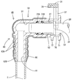
【解決手段】 管継手本体40は硬質の樹脂材よりなるとともに、全体としてL字状に屈曲している。管継手本体40の一端は金属製のパイプ20が接続されるパイプ接続部50とされ、他端側は燃料チューブTが接続されるチューブ接続部60とされている。この管継手本体40は、例えば燃料タンクの側面に突出した状態で装着されるため、メンテナンス作業を行う際には、他の部品や作業工具が当該管継手本体40にぶつかったりする。ところが、この管継手本体40のほぼ全体はこれら外部からの衝撃を緩和するための熱収縮チューブ80によって被覆されている。そのため、係る衝撃を緩和して管継手本体40ひいてはこれに接続されるパイプ20を有効に保護することが出来る。
【選択図】 図6
PROBLEM TO BE SOLVED: To alleviate an impact applied to a pipe joint or pipe.
A pipe joint body 40 is made of a hard resin material and is bent in an L shape as a whole. One end of the pipe joint body 40 is a pipe connection portion 50 to which the metal pipe 20 is connected, and the other end side is a tube connection portion 60 to which the fuel tube T is connected. Since this pipe joint main body 40 is mounted in a state protruding from the side surface of the fuel tank, for example, other parts and work tools may hit the pipe joint main body 40 when performing maintenance work. However, almost the entire pipe joint body 40 is covered with a heat-shrinkable tube 80 for reducing the impact from the outside. Therefore, the impact can be mitigated and the pipe joint body 40 and thus the pipe 20 connected thereto can be effectively protected.
[Selection] Figure 6
Description
本発明は、管継手に関する。 The present invention relates to a pipe joint.
従来より、比較的細径の金属製の配管あるいは樹脂チューブ(配管)を接続するものとして管継手が知られている(特許文献1)。このものは、配管が接続可能とされた管継手本体(雌コネクタ部材)と、嵌め合わされた配管を抜止めするためのリテーナとを主体として構成される。これら管継手は、例えば燃料タンクから引き出される燃料管等に接続され、装着状態にあっては、燃料タンクの側方に突出している。
管継手が側方に突出していると、他の部品或いは工具等が作業中(部品組立時、或いはメンテナンス時)にそこに突き当たることがある。この場合に、その衝撃が配管と管継手の接続部分に伝わって、配管或いは管継手を傷付けるおそれがあった。
本発明は上記のような事情に基づいて完成されたものであって、管継手或いは配管に加わる衝撃を緩和することを目的とする。
If the pipe joint protrudes to the side, other parts, tools, or the like may hit there during operation (part assembly or maintenance). In this case, the impact may be transmitted to the connection portion between the pipe and the pipe joint, and the pipe or the pipe joint may be damaged.
This invention is completed based on the above situations, Comprising: It aims at relieving the impact added to a pipe joint or piping.
上記の目的を達成するための手段として、請求項1の発明は、両端が開口する貫通孔を有し、一端側が第1の配管が接続可能とされる第1配管接続部とされ他端側が第2の配管が接続可能とされる第2配管接続部とされた本体部を備えた管継手であって、前記第1・第2配管接続部は硬質樹脂材よりなるとともに、前記本体部にはクッション材よりなる衝撃緩和手段が設けられているところに特徴を有する。
As a means for achieving the above object, the invention of
請求項2の発明は、請求項1に記載のものにおいて、前記衝撃緩和手段は、前記第1或いは第2の配管組み付け後に加熱されることによって収縮して前記本体部並びに前記配管の外周に密着する熱収縮チューブよりなるところに特徴を有する。 According to a second aspect of the present invention, in the first aspect of the present invention, the impact mitigating means is contracted by being heated after the first or second pipe is assembled, and is in close contact with the outer periphery of the main body and the pipe. It is characterized by a heat shrinkable tube.
請求項3の発明は、請求項1に記載のものにおいて、前記本体部の外周或いは内周には、前記衝撃緩和手段とされた衝撃緩和層が前記本体部と一体的に形成されているところに特徴を有する。 According to a third aspect of the present invention, in the first aspect of the present invention, an impact relaxation layer serving as the impact relaxation means is integrally formed with the main body portion on the outer periphery or the inner periphery of the main body portion. It has the characteristics.
請求項4の発明は、請求項1に記載のものにおいて、前記本体部は前記第1配管接続部と前記第2配管接続部とから分割構成されるとともに、これら第1、第2配管接続部の間が、前記衝撃緩和手段とされた連結部によって繋がれているところに特徴を有する。 According to a fourth aspect of the present invention, in the first aspect of the present invention, the main body portion is divided from the first pipe connection portion and the second pipe connection portion, and the first and second pipe connection portions. Is characterized in that they are connected by a connecting portion which is the impact reducing means.
<請求項1の発明>
請求項1の発明によれば、仮に、本体部に外部から衝撃が加わったとしても、その衝撃は衝撃緩和手段によって緩和される。従って、管継手本体自体を保護することが可能となるし、また配管に伝わる衝撃も小さくなるから配管の保護にも有効である。
<Invention of
According to the first aspect of the present invention, even if an external impact is applied to the main body, the impact is alleviated by the impact mitigating means. Therefore, it is possible to protect the pipe joint body itself, and the impact transmitted to the pipe is reduced, which is effective for protecting the pipe.
<請求項2の発明>
請求項2の発明によれば、予め本体部の外周に熱収縮チューブを被せておき、配管等の組み付け後に熱収縮チューブを加熱するだけで組み付けが完了する。従って、組み付け作業性に優れる。
<Invention of Claim 2>
According to the second aspect of the present invention, the heat shrink tube is put on the outer periphery of the main body portion in advance, and the heat shrink tube is heated only after the pipes and the like are assembled. Therefore, the assembly workability is excellent.
<請求項3の発明>
請求項3の発明によれば、衝撃緩和層は本体部と一体的に成形されるから部品点数が少なくて済む。
<Invention of Claim 3>
According to the invention of claim 3, since the impact relaxation layer is formed integrally with the main body, the number of parts can be reduced.
<請求項4の発明>
請求項4の発明によれば、連結部全体がクッション材によって形成されているから、衝撃緩和性に優れる。
<Invention of Claim 4>
According to invention of Claim 4, since the whole connection part is formed with the cushioning material, it is excellent in impact relaxation property.
<実施形態1>
本発明の実施形態1を図1ないし図8によって説明する。
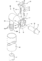
図1において、20は金属製のパイプ(本発明の第1の配管に相当する)であって、その先端寄りの位置には抜止めフランジ21が全周に亘って形成されている。この金属製のパイプ20は例えば、燃料タンク(図示せず)に対して同燃料タンクの側面から突出するように装着される。
<
A first embodiment of the present invention will be described with reference to FIGS.
In FIG. 1,
一方、40は管継手本体(本発明の本体部に相当する)であって、筒状をなすパイプ接続部(本発明の第1配管接続部に相当する)50の端部に下向きに屈曲するチューブ接続部(本発明の第2配管接続部に相当する)60を設けてなる。 パイプ接続部50の内部には導入孔51が形成されており、前方より前記パイプ20を受け入れ可能としている。一方、チューブ接続部60の内部には導入孔51に連なり下方に開放する連通孔61が形成されるとともに、その外周面には環状をなす抜止め突条62Aが軸線に沿って複数個形成されており、そこに合成ゴム製の燃料チューブ(本発明の第2の配管に相当する)Tが外嵌されるようになっている。また、チューブ接続部60の下端部分は先細りしているが、これは燃料チューブTの組み付けを円滑に行うための案内部62Bである。
尚、導入孔51並びに連通孔61が本発明の貫通孔に相当するものである。
On the other hand, 40 is a pipe joint main body (corresponding to the main body portion of the present invention), and bends downward at the end of a tubular pipe connection portion (corresponding to the first pipe connection portion of the present invention) 50. A tube connection part (corresponding to the second pipe connection part of the present invention) 60 is provided. An
The
図2に示すように、導入孔51の軸芯方向の途中には段差状に拡径された中間部52が形成されている。この中間部52には2つのシールリング24A、24Bが嵌着されている。この両シールリング24はパイプ20の外周面に密着してパイプ20と導入孔51の孔壁との間のシールを行っている。さらに、導入孔51においてパイプ20の入り口となる側(図2における右側)には挿入部54が形成されている。挿入部54の内径は中間部52の内径より更に大径に形成されており、そこには、パイプ20の抜止めフランジ21が挿入されるようになっている(図5参照)。
As shown in FIG. 2, an
また、管継手本体40の外周側でパイプ20の入り口となる部分には、前後一対の鍔縁71、72が周方向に張り出すようにして形成されている。この鍔縁71、72はほぼ正方形状をなすとともに、両鍔縁71、72の間は、次述するパイプリテーナ30を装着するための取付部74とされている。この取付部74は筒形をなすとともに、上面のうち鍔縁71寄りの部分には一対の窓部77が形成されている。これら両窓部77は導入孔51に連通しており、同窓部77を介してパイプリテーナ30の抜止め片37が導入孔51に出入りするようになっている。また、両窓部77間には鍔縁71に連なるリブ74Aが形成されているが、これは窓部77を形成したことによって取付部74の強度が低下しないようにするためのものである。
Further, a pair of front and
また、取付部74の左右の側面であって、高さ方向の中央部分には導入孔51に対して連通するロック孔78が設けられるとともに、取付部74の下面部76は平坦なロック面とされている。これらロック孔78並びに下面部76に対して、パイプリテーナ30の備える係止爪35が選択的に係止可能とされており、これにて、パイプリテーナ30は管継手本体40に対してパイプ20の挿抜を許容する仮止め位置(図4に示す位置)と、パイプ20を抜止めするロック位置(図6に示す位置)との二段階でロックするようになっている。
In addition, a
パイプリテーナ30は合成樹脂製であって、板状の基部31を有するとともに、その前縁(図1に示す手前側の側縁)に下向きに伸びる一対の係止アーム33及び同じく下向きに伸びる一対の抜止め片37を設けている。基部31に対しては両係止アーム33が外側に配され、抜止め片37が係止アーム33の内側に配されている。このうち、抜止め片37は窓部77に挿入可能な幅寸法を持って形成されるとともに、その基端部分の内周側は弧状に形成されており、先端部分に比べて基端部分の剛性がアップされ撓み変形不能とされている。また、両抜止め片37の間には基部31に向かって真っ直ぐに切り欠かかれたスリット38が設けられているが、これは、前記したリブ74Aに対する逃がしである。
The
一方、係止アーム33は抜止め片37より下方への張り出し量が多く形成されるとともに、その全高に亘ってほぼ一定の横幅寸法を持って形成され、弾性変位可能とされている。この係止アーム33は、先端部分に内向きに屈曲する係止爪35を設けており、パイプリテーナ30が図4に示す仮止め位置にあるときに、係止爪35がロック孔78に係止するようになっている。
On the other hand, the
これにより、パイプリテーナ30は仮止め位置において、引き抜き・押し込み方向に関する両動作が規制されることとなる。また、この仮止め位置では、基部31が管継手本体40の外周面より所定高さ離れて位置するとともに、抜止め片37は窓部77に対して一部が差し込まれた状態にはあるが導入孔51からは完全に退避した状態にあって、導入孔51に対するパイプ20の挿抜を可能としている。
As a result, the
次に、ロック孔78に対する係止爪35のロックの解除構造について説明すると、係止爪35における嵌合方向前側の側面には内側に下り勾配となった案内斜面35Aが形成されるとともに、仮止め位置においてはロック孔78に係止した係止爪35の先端部分が導入孔51内に進入した状態にある。この係止爪35は、パイプ20が正規深さ、すなわち図5に示す位置であって抜止めフランジ21の前面が挿入部54に内装されるリング27の端面に当接する位置(以下、正規挿入位置とする)まで差し込まれると、抜止めフランジ21と干渉する位置関係にあって、抜止めフランジ21が係止爪35をロック解除方向に拡開させるようになっている。
Next, the unlocking structure of the
これにより、係止爪35とロック孔78との係止が解かれることになり、この状態から押し込み方向に力が作用すると、パイプリテーナ30の係止爪35は更に拡開されることでロック孔78に対するロックが完全に解かれて図示下方に変位可能となる。尚、ロック孔78の孔縁の下部は径方向外向きに下降傾斜しているが、そこは係止爪35のロック解除動作を案内するための誘導斜面78Aである。
As a result, the locking
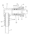
図6、図8に示すロック位置においては、パイプリテーナ30の係止爪35が取付部74の下面部76に対して係止するとともに、パイプリテーナ30の抜止め片37が導入孔51内に進入して抜止めフランジ21に係止する。これにより、パイプ20は管継手本体40に対して抜止め状態に保持される。
6 and 8, the locking
また、ロック位置において基部31の下面は管継手本体40の上面、すなわち両鍔縁71、72の上端面にほぼ当接するようになっているが、基部31の下面側には管継手本体40に対するロックを解除するための解除凹部39が凹設され鍔縁72の上端面との間に僅かな隙間が出来るようになっている。この隙間から解除凹部39内に解除治具(図示せず)が差し込み可能とされており、所定の解除操作を行うことで、ロック孔78に対する係止爪35の係止を解除することが出来るようになっている。
In the locked position, the lower surface of the
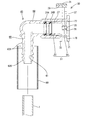
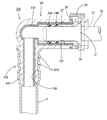
ところで、管継手本体40はパイプ20並びに燃料チューブTが接続されるから接続部分の強度確保を目的として材料に、硬質製の樹脂材(例えば、ガラス繊維入りナイロン)が使用されている。しかし、このような硬質製の材料は衝撃に弱いため、図4に示すように管継手本体40を熱収縮チューブ(本発明の衝撃緩和手段に相当する)80によって被覆して管継手本体40の保護を図っている。熱収縮チューブ80はクッション性を有する軟質の材料(例えば、ポリオレフィン系のもの或いはシリコーンゴム製のもの)よりなるとともに、収縮前の状態にあっては図2、図3に示すように、管継手本体40より大径な円筒状をなし管継手本体40に対して遊嵌されるようになっている。また、熱収縮チューブ80の全長は管継手本体40の全長よりやや短い設定とされているが、これは熱収縮チューブ80によって管継手本体40の外周を被覆した際に、熱収縮チューブ80がパイプリテーナ30の基部31に干渉するのを回避するために、熱収縮チューブ80の全長を管継手本体40の全長に比べて基部31の長さ分短く設定しているためである。
By the way, since the pipe
また、熱収縮チューブ80は、チューブ接続部60に対して燃料チューブTを装着した後に、ドライヤー等の加熱手段によって加熱される。これにより熱収縮チューブ80は収縮して、パイプ接続部50側にあっては同パイプ接続部50の外周のうちパイプリテーナ30の基部31を避けたほぼ全長に亘って隙間なく密着する。そして、チューブ接続部60側にあってはチューブ接続部60の全体を燃料チューブTの外周から被覆するようになっている。これにより、管継手本体40のほぼ全体が熱収縮チューブ80によって被覆される。
The heat shrinkable
次に、上記のように構成された本実施形態の作用効果を具体的に説明する。
管継手本体40の接続作業を行うには、管継手本体40に対しパイプリテーナ30を仮止め位置にセットするとともに、熱収縮チューブ80を燃料チューブTに通しておく。その後、熱収縮チューブ80が通された燃料チューブTをチューブ接続部60に対して下方から押し込む。これにより、燃料チューブTはチューブ接続部60の先端に設けられる案内部62Bによって径方向外側に押し拡げられつつ、チューブ接続部60の外周に嵌め合わされてゆく。やがて、燃料チューブTの上端がチューブ接続部60の上端まで達し、燃料チューブTの組み付けが完了する。この取り付け状態において燃料チューブTは、図3に示すようにチューブ接続部60の外周に密着した状態にあって、チューブ接続部60の備える抜止め突条62Aによって抜止め状態に保持される。
Next, the effect of this embodiment comprised as mentioned above is demonstrated concretely.
In order to connect the pipe joint
燃料チューブTの嵌合作業に続いて、管継手本体40を燃料タンクに対して装着する。それには、燃料タンクに取り付けられたパイプ20に対して管継手本体40の導入孔51を位置合わせして管継手本体40をパイプ20に向けて押し込んでゆく。
Following the fitting operation of the fuel tube T, the pipe
すると、パイプ20の抜止めフランジ21は導入孔51の孔壁に摺接しつつ内部へと前進してゆく。やがて、抜止めフランジ21はロック孔78から導入孔51内に突出する係止アーム33の案内斜面35Aに当接する。その後の挿入過程で、抜止めフランジ21は係止アーム33を拡開させつつ更に前進してゆき、やがて、パイプ20は図5に示す正規挿入位置に至る。
Then, the retaining
この正規挿入位置では、係止爪35とロック孔78との係止が解かれた状態にある。そのため、この状態から仮係止位置にあるパイプリテーナ30を下向きに押し込んでやると、パイプリテーナ30は鍔縁71、72による案内作用を受けて下向きに移動してゆく。やがて、パイプリテーナ30が図6に示すロック位置に至ると、係止アーム33が弾性復帰して、係止爪35が取付部74の下面部76に係止する。このロック位置においては図8に示すように、抜止め片37が窓部77を介して導入孔51内に進入して抜止めフランジ21に対して係止する。これにより、パイプ20は抜止め状態に保持される。
In this regular insertion position, the locking
また、このパイプ20に対する管継手本体40の組み付けと前後して、管継手本体40に対する熱収縮チューブ80の取り付けを行う。それには、図3に示すように、熱収縮チューブ80の下端とチューブ接続部60の下端とがほぼ揃うように位置合わせしておき、その状態からドライヤー等の加熱手段によって熱収縮チューブ80を加熱する。これにより、熱収縮チューブ80は収縮して図6に示すように、チューブ接続部60の下端から上端に至る全域並びに、パイプ接続部50のうちパイプリテーナ30が装着される前端部を除く全範囲が同熱収縮チューブ80によって覆われることとなる。
Further, the
本実施形態によれば、管継手本体40の外周部分はクッション性を有する熱収縮チューブ80によって覆われている。従って、仮にメンテナンス或いは組み付け作業中に管継手本体40に他の部品或いは作業工具等が干渉して管継手本体40に外部から衝撃が加わったとしても、その衝撃は熱収縮チューブ80によって緩和される。従って、管継手本体40並びに、これに接続されるパイプ20を有効に保護出来る。また、熱収縮チューブ80は、管継手本体40に対する燃料チューブTの接続作業後に加熱するだけで組み付けが完了するから、組み付け作業性にも優れる。
According to this embodiment, the outer peripheral part of the pipe joint
<実施形態2>
実施形態2を図9を参照して説明する。
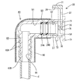
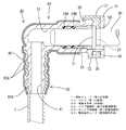
実施形態1では、衝撃緩和手段を管継手本体40とは別部品からなる熱収縮チューブ80を管継手本体40の外周に被覆したが、実施形態2では管継手本体100の内周側に衝撃緩和層110を一体的に形成している。より具体的に説明すると、衝撃緩和層110はクッション性を有する軟質の材料(例えば、熱可塑性のエラストマ等)よりなるとともに、パイプ接続部101側にあっては導入孔102のうちパイプリテーナ30が装着される部分を除く全孔壁、チューブ接続部105側にあっては連通孔106の全孔壁に亘って形成されている。
<Embodiment 2>
A second embodiment will be described with reference to FIG.
In the first embodiment, the outer periphery of the pipe
このように、内周側に衝撃緩和層110を設けておけば、管継手本体100の外周部分に衝撃緩和層と形成した場合と同様に管継手本体100とパイプ20との接続部を保護することが出来る。というのも管継手本体100に衝撃が加わった場合には、管継手本体100とパイプ20との接続部分が最も損傷を受けやすい場所であるが、内周側に衝撃緩和層110を形成しておけば、パイプ20とパイプ接続部101との間にクッション性を持たせることが出来、当該部分に加わる衝撃を緩和することが出来るからである。
As described above, if the
また、このように衝撃緩和層110を管継手本体100と一体的に形成することで、部品点数も削減される。その他の構成については実施形態1と同様であるため同一部品には同一符号を付して重複した説明を省略する。
In addition, by forming the
<実施形態3>
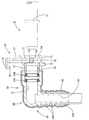
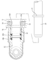
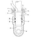
実施形態1では、パイプ接続部50とチューブ接続部60とを一体的に形成するとともに、これに別部品からなる熱収縮チューブ80を被覆したが、実施形態3ではパイプ接続部121とチューブ接続部126とが分割構成されており、これら両接続部121、126の間をクッション性を有する軟質の材料(例えば、熱可塑性のエラストマ等)よりなる連結部131によって構成している。このような構成であれば、メンテナンス等の作業中に最も他の部品が干渉し易い出っ張り部分、すなわち両接続部121、126同士が繋がれるコーナ部分(図10におけるR部分)の全体がクッション材(軟質材)により形成されることとなるから衝撃の緩和に有効である。加えて、これら両接続部121、126並びに連結部131を一体的に成形することによって部品点数が削減される。その他の構成については実施形態1と同様であるため同一部品には同一符号を付して重複した説明を省略する。
<Embodiment 3>
In the first embodiment, the
<他の実施形態>
本発明は上記記述及び図面によって説明した実施形態に限定されるものではなく、例えば次のような実施形態も本発明の技術的範囲に含まれ、さらに、下記以外にも要旨を逸脱しない範囲内で種々変更して実施することができる。
<Other embodiments>
The present invention is not limited to the embodiments described with reference to the above description and drawings. For example, the following embodiments are also included in the technical scope of the present invention, and further, within the scope not departing from the gist of the invention other than the following. Various modifications can be made.
(1)実施形態1においては、熱収縮チューブ80を1層の構造としたが、多層の構造としてもよい。
(1) Although the heat-
(2)実施形態1においては、管継手本体40のほぼ全体を熱収縮チューブ80によって被覆したが、例えば、最も衝撃が加わり易いコーナ部分のみを熱収縮チューブ80によって被覆してもよい。
(2) In the first embodiment, almost the entire pipe joint
(3)実施形態2においては、管継手本体100の内周側に衝撃緩和層110を設けたが、管継手本体100の外周側に衝撃緩和層を設けてもよい。
(3) In the second embodiment, the
T…燃料チューブ(第2の配管)
20…パイプ(第1の配管)
40…管継手本体(本体部)
50…パイプ接続部(第2配管接続部)
60…チューブ接続部(第1配管接続部)
80…熱収縮チューブ(衝撃緩和手段)
T ... Fuel tube (second pipe)
20 ... pipe (first pipe)
40 ... Pipe fitting body (main body)
50 ... Pipe connection (second pipe connection)
60 ... Tube connection part (first pipe connection part)
80 ... Heat shrinkable tube (impact mitigation means)
Claims (4)
前記第1・第2配管接続部は硬質樹脂材よりなるとともに、前記本体部にはクッション材よりなる衝撃緩和手段が設けられていることを特徴とする管継手。 Both ends have through-holes, one end side is a first pipe connection portion that can be connected to the first pipe, and the other end side is a second pipe connection portion that can be connected to the second pipe. A pipe joint having a main body,
The first and second pipe connecting portions are made of a hard resin material, and the body portion is provided with impact relaxation means made of a cushion material.
Priority Applications (1)
| Application Number | Priority Date | Filing Date | Title |
|---|---|---|---|
| JP2004112268A JP2005299700A (en) | 2004-04-06 | 2004-04-06 | Pipe fitting |
Applications Claiming Priority (1)
| Application Number | Priority Date | Filing Date | Title |
|---|---|---|---|
| JP2004112268A JP2005299700A (en) | 2004-04-06 | 2004-04-06 | Pipe fitting |
Publications (1)
| Publication Number | Publication Date |
|---|---|
| JP2005299700A true JP2005299700A (en) | 2005-10-27 |
Family
ID=35331485
Family Applications (1)
| Application Number | Title | Priority Date | Filing Date |
|---|---|---|---|
| JP2004112268A Pending JP2005299700A (en) | 2004-04-06 | 2004-04-06 | Pipe fitting |
Country Status (1)
| Country | Link |
|---|---|
| JP (1) | JP2005299700A (en) |
Cited By (1)
| Publication number | Priority date | Publication date | Assignee | Title |
|---|---|---|---|---|
| WO2014002606A1 (en) * | 2012-06-29 | 2014-01-03 | 株式会社東郷製作所 | Connector cover |
Citations (3)
| Publication number | Priority date | Publication date | Assignee | Title |
|---|---|---|---|---|
| JPS53122134A (en) * | 1977-03-31 | 1978-10-25 | Nitto Electric Ind Co Ltd | Protective method for connecting part of pipe material |
| JPH0639949A (en) * | 1992-07-27 | 1994-02-15 | Furukawa Electric Co Ltd:The | Composite hollow molding |
| JP2004190755A (en) * | 2002-12-10 | 2004-07-08 | Mitsubishi Plastics Ind Ltd | Pipe fittings |
-
2004
- 2004-04-06 JP JP2004112268A patent/JP2005299700A/en active Pending
Patent Citations (3)
| Publication number | Priority date | Publication date | Assignee | Title |
|---|---|---|---|---|
| JPS53122134A (en) * | 1977-03-31 | 1978-10-25 | Nitto Electric Ind Co Ltd | Protective method for connecting part of pipe material |
| JPH0639949A (en) * | 1992-07-27 | 1994-02-15 | Furukawa Electric Co Ltd:The | Composite hollow molding |
| JP2004190755A (en) * | 2002-12-10 | 2004-07-08 | Mitsubishi Plastics Ind Ltd | Pipe fittings |
Cited By (2)
| Publication number | Priority date | Publication date | Assignee | Title |
|---|---|---|---|---|
| WO2014002606A1 (en) * | 2012-06-29 | 2014-01-03 | 株式会社東郷製作所 | Connector cover |
| JP2014009755A (en) * | 2012-06-29 | 2014-01-20 | Togo Seisakusho Corp | Connector cover |
Similar Documents
| Publication | Publication Date | Title |
|---|---|---|
| US4915420A (en) | Connector for connecting pipe | |
| US4946205A (en) | Connector for connecting small diameter pipe | |
| JP5198361B2 (en) | Retainer structure | |
| JP3754082B2 (en) | Quick connect fluid fitting with collet retainer | |
| US8393058B2 (en) | Clip | |
| JP6131183B2 (en) | Connector assembly | |
| US7690876B2 (en) | Clip | |
| JP2007032673A (en) | Pipe connection structure | |
| JP7491704B2 (en) | Retaining parts | |
| JP2007010108A (en) | Quick connector protective cover | |
| JP6139126B2 (en) | Pipe connector | |
| CN101002048A (en) | Coupling | |
| CN115152112B (en) | Wire protecting sleeve | |
| JP3323022B2 (en) | mechanical pencil | |
| JP5869438B2 (en) | Connector cover | |
| JP4851830B2 (en) | Grommet | |
| JP2005299700A (en) | Pipe fitting | |
| US20090121478A1 (en) | Male-Female member assembly | |
| US6796582B2 (en) | Assembly consisting of an inflator, a housing and a retainer | |
| JP2013053657A (en) | Connector plug | |
| JP7581005B2 (en) | connector | |
| JP2006022911A (en) | connector | |
| JP2007524789A (en) | Quick connect collet holder with self-centering structure | |
| JP5787441B2 (en) | Piping connector | |
| JP4982321B2 (en) | Quick connector |
Legal Events
| Date | Code | Title | Description |
|---|---|---|---|
| RD04 | Notification of resignation of power of attorney |
Free format text: JAPANESE INTERMEDIATE CODE: A7424 Effective date: 20060531 |
|
| A621 | Written request for application examination |
Free format text: JAPANESE INTERMEDIATE CODE: A621 Effective date: 20070406 |
|
| RD02 | Notification of acceptance of power of attorney |
Free format text: JAPANESE INTERMEDIATE CODE: A7422 Effective date: 20070406 |
|
| A977 | Report on retrieval |
Free format text: JAPANESE INTERMEDIATE CODE: A971007 Effective date: 20090910 |
|
| A131 | Notification of reasons for refusal |
Free format text: JAPANESE INTERMEDIATE CODE: A131 Effective date: 20100413 |
|
| A02 | Decision of refusal |
Free format text: JAPANESE INTERMEDIATE CODE: A02 Effective date: 20100803 |