JP2005299913A - Front forks such as motorcycles - Google Patents
Front forks such as motorcycles Download PDFInfo
- Publication number
- JP2005299913A JP2005299913A JP2004155192A JP2004155192A JP2005299913A JP 2005299913 A JP2005299913 A JP 2005299913A JP 2004155192 A JP2004155192 A JP 2004155192A JP 2004155192 A JP2004155192 A JP 2004155192A JP 2005299913 A JP2005299913 A JP 2005299913A
- Authority
- JP
- Japan
- Prior art keywords
- inner tube
- oil
- gap
- front fork
- tube
- Prior art date
- Legal status (The legal status is an assumption and is not a legal conclusion. Google has not performed a legal analysis and makes no representation as to the accuracy of the status listed.)
- Withdrawn
Links
Images
Classifications
-
- B—PERFORMING OPERATIONS; TRANSPORTING
- B62—LAND VEHICLES FOR TRAVELLING OTHERWISE THAN ON RAILS
- B62K—CYCLES; CYCLE FRAMES; CYCLE STEERING DEVICES; RIDER-OPERATED TERMINAL CONTROLS SPECIALLY ADAPTED FOR CYCLES; CYCLE AXLE SUSPENSIONS; CYCLE SIDECARS, FORECARS, OR THE LIKE
- B62K25/00—Axle suspensions
- B62K25/04—Axle suspensions for mounting axles resiliently on cycle frame or fork
- B62K25/06—Axle suspensions for mounting axles resiliently on cycle frame or fork with telescopic fork, e.g. including auxiliary rocking arms
- B62K25/08—Axle suspensions for mounting axles resiliently on cycle frame or fork with telescopic fork, e.g. including auxiliary rocking arms for front wheel
Landscapes
- Engineering & Computer Science (AREA)
- Mechanical Engineering (AREA)
- Fluid-Damping Devices (AREA)
- Axle Suspensions And Sidecars For Cycles (AREA)
Abstract
【課題】 アウタチューブの開口部の内周に設けたブッシュ、オイルシールリップ等の潤滑用のオイルの充填量を少なくして、軽量化を図ることのできる二輪車等のフロントフォークを安価に提供すること。
【解決手段】 二輪車等のフロントフォーク100において、アウタチューブ101とインナチューブ102の間に、2つのブッシュ103、104にて区画される環状油間隙121を設け、インナチューブ102の内周に可動隔壁部材130を設け、インナチューブ102の先端側に油室122を区画するとともに、インナチューブ102の基端側に気体室123を区画し、環状油間隙121を油室122に連通するともに、可動隔壁部材130にて、環状油間隙121と油室122を気体室123に対して密封区画したもの。
【選択図】図2PROBLEM TO BE SOLVED: To provide a front fork such as a two-wheeled vehicle that can be reduced in weight by reducing a filling amount of lubricating oil such as a bush and an oil seal lip provided on an inner periphery of an opening of an outer tube at low cost. about.
In a front fork 100 such as a two-wheeled vehicle, an annular oil gap 121 defined by two bushes 103, 104 is provided between an outer tube 101 and an inner tube 102, and a movable partition wall is provided on the inner periphery of the inner tube 102. The member 130 is provided, the oil chamber 122 is defined on the distal end side of the inner tube 102, the gas chamber 123 is defined on the proximal end side of the inner tube 102, the annular oil gap 121 communicates with the oil chamber 122, and the movable partition wall In the member 130, the annular oil gap 121 and the oil chamber 122 are hermetically partitioned from the gas chamber 123.
[Selection] Figure 2
Description
本発明は、二輪車等のフロントフォークに関する。 The present invention relates to a front fork such as a motorcycle.
特許文献1には、スタンドパイプ(インナチューブ)及び/又はスライドパイプ(アウタチューブ)に懸架ばね要素及び/又は減衰力発生要素を含まず、スタンドパイプとスライドパイプを伸縮摺動自在にしたフロントフォークが開示されている。 Patent Document 1 discloses a front fork that does not include a suspension spring element and / or a damping force generation element in a stand pipe (inner tube) and / or a slide pipe (outer tube), and that allows the stand pipe and the slide pipe to slide freely. Is disclosed.
特許文献1のフロントフォークは、スライドパイプの開口部の内周に設けた滑り軸受4(ブッシュ)を介して、スライドパイプ内にスタンドパイプを摺動可能に挿入し、スライドパイプとスタンドパイプの内室には、滑り軸受4の潤滑用の潤滑剤であるオイルを充填している。そして、スライドパイプとスタンドパイプの内室内に、中空の成形体を設けることにより、オイルの充填量を少なくし、フロントフォークの軽量化を図っている。
特許文献1のフロントフォークでは、スタンドパイプの開口部の内周に設けたブッシュに対する潤滑用のオイルの充填量を少なくして軽量化を図るため、特注品となる中空の成形体を用いる必要があり、高価になる。 In the front fork of Patent Document 1, it is necessary to use a hollow molded body that is a custom-made product in order to reduce the amount of lubrication oil filled in the bush provided on the inner periphery of the opening of the stand pipe and reduce the weight. Yes, it becomes expensive.
本発明の課題は、アウタチューブの開口部の内周に設けたブッシュ、オイルシールリップ等の潤滑用のオイルの充填量を少なくして、軽量化を図ることのできる二輪車等のフロントフォークを安価に提供することにある。 An object of the present invention is to reduce the amount of lubricating oil such as bushes and oil seal lips provided on the inner periphery of the opening of the outer tube and reduce the weight of a front fork such as a two-wheeled vehicle. There is to provide to.
請求項1の発明は、アウタチューブ内にインナチューブを摺動自在に挿入した二輪車等のフロントフォークにおいて、前記インナチューブの先端を前記アウタチューブの開口部から該アウタチューブ内に挿入し、該アウタチューブの開口部側の内周と、該開口部から軸方向に間隔を置いた基端側の内周に、該インナチューブをガイドする2つのブッシュを嵌着し、前記アウタチューブと前記インナチューブの間に、該2つのブッシュにて区画される環状油間隙を設け、前記インナチューブの内周に可動隔壁部材を設け、該インナチューブの先端側に油室を区画するとともに、該インナチューブの基端側に気体室を区画し、前記環状油間隙を前記インナチューブの先端側の油室に連通するとともに、前記可動隔壁部材にて、前記環状油間隙と前記油室を前記気体室に対して密封区画したものである。 According to a first aspect of the present invention, in a front fork such as a two-wheeled vehicle in which an inner tube is slidably inserted into an outer tube, the tip of the inner tube is inserted into the outer tube from an opening of the outer tube, and the outer tube Two bushes for guiding the inner tube are fitted to the inner periphery on the opening side of the tube and the inner periphery on the proximal end side spaced apart from the opening in the axial direction, and the outer tube and the inner tube An annular oil gap defined by the two bushes is provided between them, a movable partition member is provided on the inner periphery of the inner tube, an oil chamber is defined on the tip side of the inner tube, and the inner tube A gas chamber is defined on the proximal end side, and the annular oil gap is communicated with the oil chamber on the distal end side of the inner tube. An oil chamber in which sealed compartment relative to the gas chamber.
請求項2の発明は、請求項1の発明において更に、前記可動隔壁部材を、前記インナチューブの先端側の内周に設け、前記油室の容積を小さくしたものである。 According to a second aspect of the present invention, in the first aspect of the invention, the movable partition member is further provided on the inner periphery of the inner tube on the distal end side to reduce the volume of the oil chamber.
請求項3の発明は、請求項1又は2に記載の発明において更に、前記アウタチューブの基端側の内周に形成した環状溝内に、前記ブッシュを、合口隙間を有する状態で装着し、前記環状油間隙と前記インナチューブの先端側の油室とを、上記ブッシュの合口間隙を介して連通したものである。 According to a third aspect of the present invention, in the invention of the first or second aspect, the bush is mounted in an annular groove formed in the inner periphery on the proximal end side of the outer tube in a state having a gap. The annular oil gap and the oil chamber on the tip side of the inner tube communicate with each other via the joint gap of the bush.
請求項4の発明は、請求項1又は2の発明において更に、前記インナチューブに、該インナチューブの先端側の油室と前記環状油間隙を、常時連通する油孔を設けたものである。 According to a fourth aspect of the present invention, in the first or second aspect of the present invention, the inner tube is provided with an oil hole that always communicates the oil chamber on the distal end side of the inner tube and the annular oil gap.
(請求項1)
(a)可動隔壁部材は、アウタチューブとインナチューブ間の環状油間隙及び可動隔壁部材の下部の油室を、可動隔壁部材の上部の気体室に対し押し下げて容積を小さくした状態で密封区画する。インナチューブの外周に付着して環状油間隙に浸入したオイルは、インナチューブの上下動に連れて上部のブッシュ、オイルシールのリップを潤滑する。また、環状油間隙にフルに充填したオイルは、直接ブッシュを潤滑する。可動隔壁部材は上下動により、インナチューブの先端の油室への進入退出に伴う体積補償及び温度補償を行なう。
(Claim 1)
(a) The movable partition member seals the annular oil gap between the outer tube and the inner tube and the lower oil chamber of the movable partition member against the gas chamber above the movable partition member so as to reduce the volume. . The oil adhering to the outer periphery of the inner tube and entering the annular oil gap lubricates the upper bush and the lip of the oil seal as the inner tube moves up and down. Also, the oil that is fully filled in the annular oil gap directly lubricates the bush. The movable partition member moves up and down to perform volume compensation and temperature compensation associated with entry and exit of the oil tube at the tip of the inner tube.
可動隔壁部材は、フリーピストン又はゴム等のブラダからなるが、従来技術の合成樹脂パイプ等からなる中空の成形体のような特注品と異なり、汎用品である等により安価である。 The movable partition member is made of a bladder such as a free piston or rubber, but unlike a custom-made product such as a hollow molded body made of a synthetic resin pipe or the like of the prior art, it is inexpensive because it is a general-purpose product.
その結果、可動隔壁部材により下部の油室の容積を小さくして気体室の容積を大きくし、余分なオイルの量を少なくし、アウタチューブの開口部のブッシュ、オイルシール等を潤滑する潤滑用のオイルの充填量を少なくし、軽量化を図ったフロントフォークを安価に提供できる。 As a result, the movable partition member reduces the volume of the lower oil chamber, increases the volume of the gas chamber, reduces the amount of excess oil, and lubricates the bushing, oil seal, etc. of the outer tube opening. The front fork can be provided at low cost by reducing the amount of oil filled and reducing the weight.
(請求項2)
(b)可動隔壁部材を、インナチューブの先端側の内周に設けることにより、可動隔壁部材の下部の油室の容積をより小さくし、より軽量化を図ることができる。
(Claim 2)
(b) By providing the movable partition wall member on the inner circumference on the tip side of the inner tube, the volume of the oil chamber below the movable partition wall member can be further reduced and the weight can be further reduced.
(請求項3)
(c)アウタチューブの内周に本来的に設けられるブッシュの合口隙間を、環状油間隙とインナチューブの先端側油室との連通路として利用することにより、上述(a)、(b)のフロントフォークの一層の安価を図ることができる。
(Claim 3)
(c) By using the joint gap of the bush originally provided on the inner periphery of the outer tube as a communication path between the annular oil gap and the oil chamber on the tip side of the inner tube, the above-mentioned (a) and (b) It is possible to further reduce the cost of the front fork.
(請求項4)
(d)インナチューブの先端側の油室と環状油間隙を、常時連通する油孔をインナチューブに設けることにより、上述(a)、(b)のフロントフォークの一層の安価を図ることができる。
(Claim 4)
(d) By providing the inner tube with an oil hole that always communicates with the oil chamber on the tip end side of the inner tube and the annular oil gap, it is possible to further reduce the cost of the front fork described in (a) and (b) above. .
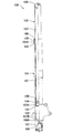
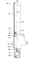
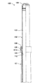
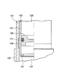
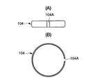
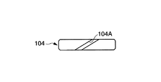
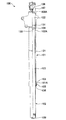
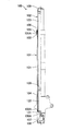
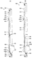
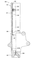
図1はフロントフォークの最伸張状態を示す半断面図、図2は図1のフロントフォークの下部拡大図、図3は図1のフロントフォークの上部拡大図、図4は図2の要部拡大図、図5はブッシュを示し、(A)は正面図、(B)は平面図、図6はブッシュの変形例を示す正面図、図7はフロントフォークのオイル注入時状態を示す半断面図、図8はフロントフォークの最圧縮状態を示す半断面図、図9はフロントフォークの変形例を示し、(A)は最圧縮状態を示す半断面図、(B)は最伸張状態を示す半断面図、図10は図9(B)の要部拡大図である。 1 is a half sectional view showing the most extended state of the front fork, FIG. 2 is an enlarged view of the lower portion of the front fork in FIG. 1, FIG. 3 is an enlarged view of the upper portion of the front fork in FIG. FIG. 5 shows a bush, (A) is a front view, (B) is a plan view, FIG. 6 is a front view showing a modification of the bush, and FIG. 7 is a half sectional view showing a state of the front fork during oil injection. 8 is a half sectional view showing the most compressed state of the front fork, FIG. 9 is a modified example of the front fork, (A) is a half sectional view showing the most compressed state, and (B) is a half sectional view showing the most expanded state. Sectional drawing and FIG. 10 are the principal part enlarged views of FIG.9 (B).
二輪車等の正立型フロントフォーク100は、図1〜図3に示す如く、車軸側のアウタチューブ101に、車体側のインナチューブ102を摺動自在にて正立にしたものである。フロントフォーク100は、懸架スプリングや減衰力発生装置を含まない。
As shown in FIGS. 1 to 3, an upright
フロントフォーク100は、インナチューブ102の先端102Aをアウタチューブ101の上端開口部101Aからアウタチューブ101内に挿入する。そして、アウタチューブ101の内周の上下2位置、換言すれば、アウタチューブ101の上端開口部101A側の内周と、上端開口部101Aから軸方向に間隔をおいた基端側の内周に、インナチューブ102をガイドする上下2つのブッシュ103、104を嵌着している。アウタチューブ101の上端開口部101Aには、オイルシール105、ダストシール106が嵌着される。
The
アウタチューブ101の基端は車軸ブラケット107を介して車軸に結合され、インナチューブ102は不図示のアッパ及びロアのブラケットを介して車体側に支持される。
The proximal end of the
アウタチューブ101の基端に封着された車軸ブラケット107の底部にはボルト孔108Aが設けられ、ボルト孔108Aには封止ボルト108が着脱される。インナチューブ102の上端開口部(基端)にはキャップ109が封着される。
A
しかるに、フロントフォーク100にあっては、図4に示す如く、アウタチューブ101の下端(基端側)内周に切削加工により環状溝111を形成し、この環状溝111内に、環状の前述した下部ブッシュ104を装着している。環状溝111は、アウタチューブ101の内周面内で、軸方向の両側部を段差によって閉じた凹溝からなる。下部ブッシュ104は、図5に示す如く、環状体からなり、自由状態で、ブッシュ104の軸方向に沿う真直状をなす合口隙間104Aを有し、合口隙間104Aを有する状態で環状溝111に装着される。下部ブッシュ104は、アウタチューブ101が車軸ブラケット107と螺合締結されていない状態で、アウタチューブ101の下端開口部101Bから、アウタチューブ101の内径に対する弾性的縮径状態で挿入され、環状溝111の溝底に対し弾性的に拡径して装着される。
However, in the
フロントフォーク100の組付状態で、アウタチューブ101の内周とインナチューブ102の外周の間の環状の隙間は、下部ブッシュ104の板厚より小さく形成され、環状溝111に装着されたブッシュ104は合口隙間104Aを有する。
In the assembled state of the
尚、上部ブッシュ103は、アウタチューブ101の上端開口部101A側の内周にて、上端側を開放するように切削加工された装着部112に圧入状態で装着され、合口隙間はゼロとなる。
The
従って、本実施例によれば以下の作用効果を奏する。
(1)下部ブッシュ104のための環状溝111の形成に対し、アウタチューブ101の内周を上端部又は下端部から軸方向に沿う長い範囲を切削加工する必要がないから、加工時間を短縮できる。
Therefore, according to the present embodiment, the following operational effects can be obtained.
(1) For the formation of the
アウタチューブ101の基端側の環状溝111を、アウタチューブ本体の可及的基端側に形成することにより、環状溝111を切削加工により形成する際におけるアウタチューブ101の芯振れがなくなり、環状溝111を精度良く形成することができる。
By forming the
(2)下部ブッシュ104は、環状溝111の両端部で軸方向の移動を阻止されるから、ブッシュ104が軸方向に位置ずれすることがない。
(2) Since the
(3)アウタチューブ101の内周とインナチューブ102の外周の間の隙間を、ブッシュ104の板厚より小さくしたからブッシュ104が合口隙間104Aの分、縮径してもその隙間に脱落することがない。
(3) Since the gap between the inner circumference of the
(4)従来の一端側が開放した装着部にブッシュを圧入する場合には、ブッシュの合口隙間はゼロとなるように圧入される。これに対し、本発明では、ブッシュ104は、環状溝111内で拡径し、合口隙間104Aを生じてしまう。このような本発明のブッシュ104は、合口隙間がゼロの従来の圧入ブッシュに比し、インナチューブ102の外周とのフリクションがストロークの起動初期から一定になる。理由は、ブッシュ104が環状溝111の内周に密着していないために、ブッシュ104が環状溝111内で僅かに拡径できるため、起動初期のフリクションが従来の圧入ブッシュにおけるよりも低減するものと考えられる。フリクションが一定化するから、フロントフォーク100の作動性を向上できる。特に、起動初期のフリクションが低減するから、フロントフォーク100の初期作動性を向上できる。
(4) When the bush is press-fitted into the conventional mounting portion where one end side is open, the joint gap of the bush is press-fitted so as to be zero. On the other hand, in the present invention, the
図6は、ブッシュ104の変形例であり、合口隙間104Aをブッシュ104の軸方向に対して傾斜させて形成したものである。
FIG. 6 shows a modification of the
図6のブッシュ104にあっては、合口隙間104Aをブッシュ104の軸方向に対して傾斜して形成した。その結果、ブッシュ104の周方向の全域にブッシュ104の軸受面が存在するものになる。従って、軸方向に沿う合口隙間を形成したものに比し、ブッシュ104の周方向で、インナチューブ102の外周面を軸承しない部分がなくなり、インナチューブ102の外周面に、ブッシュ104の合口隙間104Aとの摺動による疵の発生を防止できる。
In the
更に、フロントフォーク100にあっては、アウタチューブ101の内周とインナチューブ102の外周の間で、上下2つのブッシュ103、104にて区画される環状の隙間にブッシュ103、104、オイルシール105の潤滑用オイルを装填可能にし、この環状の隙間を環状油間隙121とする。
Further, in the
また、インナチューブ102の内周に可動隔壁部材130を設ける。可動隔壁部材130は、インナチューブ102の先端側に、アウタチューブ101の内周及び車軸ブラケット107の底部とともに区画する油室122を設けるとともに、インナチューブ102の基端側に気体室123を区画する。本実施例では、可動隔壁部材130は、インナチューブ102の先端側の内周に設けられ、油室122の容積を小さくする。
A
可動隔壁部材130は、インナチューブ102の内周に液密に摺動するフリーピストンからなるが、インナチューブ102の内周に外縁を封着したゴム等のブラダからなるものでも良い。
The
フロントフォーク100のオイル注入時には、図7に示す如く、アウタチューブ101を上側に、インナチューブ102を下側に配置するように倒立にし、可動隔壁部材130を、インナチューブ102の内周の先端部に設けたストッパ131に当て止めした状態で、車軸ブラケット107のボルト孔108Aから油室122にオイルを注入した後、ボルト孔108Aに封止ボルト108を封着する。フロントフォーク100の正立使用状態で、アウタチューブ101とインナチューブ102が伸縮するとき、インナチューブ102が油室122に進入した容積分だけ、可動隔壁部材130がストッパ131から上動する。図8はフロントフォーク100の最圧縮状態を示す。
When oil is injected into the
このとき、フロントフォーク100は、アウタチューブ101とインナチューブ102の間の環状油間隙121を、インナチューブ102の先端側の油室122に連通するとともに、可動隔壁部材130にて、環状油間隙121と油室122を気体室123に対して密封区画する。本実施例では、前述した下部ブッシュ104の合口隙間104Aを介して、環状油間隙121を油室122に常時連通する。
At this time, the
従って、本実施例によれば以下の作用効果を奏する。
(a)可動隔壁部材130は、アウタチューブ101とインナチューブ102間の環状油間隙121及び可動隔壁部材130の下部の油室122を、可動隔壁部材130の上部の気体室123に対し押し下げて容積を小さくした状態で密封区画する。インナチューブ102の外周に付着して環状油間隙121に浸入したオイルは、インナチューブ102の上下動に連れて上部のブッシュ103、オイルシール105のリップを潤滑する。また、環状油間隙121にフルに充填したオイルは、直接ブッシュ103、104を潤滑する。可動隔壁部材130は上下動により、インナチューブ102の先端の油室122への進入退出に伴う体積補償及び温度補償を行なう。
Therefore, according to the present embodiment, the following operational effects can be obtained.
(a) The
可動隔壁部材130は、フリーピストン又はゴム等のブラダからなるが、従来技術の合成樹脂パイプ等からなる中空の成形体のような特注品と異なり、汎用品である等により安価である。
The
その結果、可動隔壁部材130により下部の油室122の容積を小さくして気体室123の容積を大きくし、余分なオイルの量を少なくし、アウタチューブ101の開口部101Aのブッシュ103、オイルシール105等を潤滑する潤滑用のオイルの充填量を少なくし、軽量化を図ったフロントフォーク100を安価に提供できる。
As a result, the volume of the
(b)可動隔壁部材130を、インナチューブ102の先端側の内周に設けることにより、可動隔壁部材130の下部の油室122の容積をより小さくし、より軽量化を図ることができる。
(b) By providing the
(c)アウタチューブ101の内周に本来的に設けられるブッシュ104の合口隙間104Aを、環状油間隙121とインナチューブ102の先端側油室122との連通路として利用することにより、上述(a)、(b)のフロントフォーク100の一層の安価を図ることができる。
(c) By using the
尚、フロントフォーク100にあっては、図9、図10に示す如く、環状油間隙121と油室122が、インナチューブ102の側壁に設けた油孔140により常時連通されるものでも良い。図9(A)はフロントフォーク100の最圧縮状態、図9(B)、図10はフロントフォーク100の最伸張状態を示す。図9(A)、図10の最伸張状態では、インナチューブ102が油室122から抜け出た分だけ可動隔壁部材130が下動するから、油孔140は、可動隔壁部材130により閉塞されず、かつ気体室123に開口することもない、インナチューブ102の先端側の位置に設ける必要がある。
In the
このとき、下部ブッシュ104は、図5、図6に示す如くの合口隙間104Aを有する環状体からなるものでも良く、周方向に連続して合口隙間を有しない環状体からなるものでも良い。ブッシュ104が合口隙間を有しない環状体からなるときには、図9(A)の最圧縮状態で、油孔140は、ブッシュ104に閉塞されず、環状油間隙121に連通する。
At this time, the
また、フロントフォーク100にあっては、アウタチューブ101とインナチューブ102の間の環状油間隙121にオイルを充満させるものに限らず、環状油間隙121内のオイルに多少の気体が混入していても良い。環状油間隙121に気体を混入した場合にはインナチューブ102の伸縮ストロークに伴い、ブッシュ104の合口隙間104Aを作動油が流動することになるから、合口隙間104Aで減衰力が発生し、インナチューブ102の作動性が悪くなる。環状油間隙121に気体を混入させない場合には、上述の減衰力が発生せず、インナチューブ102の伸縮ストロークの作動性が良くなる。
Further, the
また、フロントフォーク100にあっては、アウタチューブ101を構成するアウタチューブ本体に車軸ブラケット107を鋳造にて一体成形したアウタチューブ101を用いるものでも良い。
Further, in the
以上、本発明の実施例を図面により詳述したが、本発明の具体的な構成はこの実施例に限られるものではなく、本発明の要旨を逸脱しない範囲の設計の変更等があっても本発明に含まれる。 The embodiment of the present invention has been described in detail with reference to the drawings. However, the specific configuration of the present invention is not limited to this embodiment, and even if there is a design change or the like without departing from the gist of the present invention. It is included in the present invention.
100 フロントフォーク
101 アウタチューブ
102 インナチューブ
103 上部ブッシュ、
104 下部ブッシュ
104A 合口隙間
111 環状溝
121 環状油間隙
122 油室
123 気体室
130 可動隔壁部材
140 油孔
100
104
Claims (4)
前記インナチューブの先端を前記アウタチューブの開口部から該アウタチューブ内に挿入し、該アウタチューブの開口部側の内周と、該開口部から軸方向に間隔を置いた基端側の内周に、該インナチューブをガイドする2つのブッシュを嵌着し、
前記アウタチューブと前記インナチューブの間に、該2つのブッシュにて区画される環状油間隙を設け、
前記インナチューブの内周に可動隔壁部材を設け、該インナチューブの先端側に油室を区画するとともに、該インナチューブの基端側に気体室を区画し、
前記環状油間隙を前記インナチューブの先端側の油室に連通するとともに、前記可動隔壁部材にて、前記環状油間隙と前記油室を前記気体室に対して密封区画したことを特徴とする二輪車等のフロントフォーク。 In front forks such as motorcycles in which the inner tube is slidably inserted into the outer tube,
The distal end of the inner tube is inserted into the outer tube from the opening of the outer tube, and the inner periphery on the opening side of the outer tube and the inner periphery on the proximal end that is axially spaced from the opening To fit two bushes for guiding the inner tube,
An annular oil gap defined by the two bushings is provided between the outer tube and the inner tube,
A movable partition member is provided on the inner periphery of the inner tube, an oil chamber is defined on the distal end side of the inner tube, and a gas chamber is defined on the proximal end side of the inner tube,
The two-wheeled vehicle characterized in that the annular oil gap communicates with an oil chamber on the tip side of the inner tube, and the annular oil gap and the oil chamber are hermetically partitioned from the gas chamber by the movable partition member. Etc. Front fork.
前記環状油間隙と前記インナチューブの先端側の油室とを、上記ブッシュの合口間隙を介して連通した請求項1又は2に記載の二輪車等のフロントフォーク。 In the annular groove formed on the inner circumference of the base end side of the outer tube, the bush is mounted in a state having a joint gap,
The front fork of a two-wheeled vehicle or the like according to claim 1 or 2, wherein the annular oil gap and the oil chamber on the tip side of the inner tube communicate with each other via a joint gap of the bush.
Priority Applications (2)
| Application Number | Priority Date | Filing Date | Title |
|---|---|---|---|
| JP2004155192A JP2005299913A (en) | 2004-03-17 | 2004-05-25 | Front forks such as motorcycles |
| EP04021389A EP1577206A3 (en) | 2004-03-17 | 2004-09-08 | Front fork of two-wheeled vehicle or the like |
Applications Claiming Priority (2)
| Application Number | Priority Date | Filing Date | Title |
|---|---|---|---|
| JP2004077228 | 2004-03-17 | ||
| JP2004155192A JP2005299913A (en) | 2004-03-17 | 2004-05-25 | Front forks such as motorcycles |
Publications (1)
| Publication Number | Publication Date |
|---|---|
| JP2005299913A true JP2005299913A (en) | 2005-10-27 |
Family
ID=34840255
Family Applications (1)
| Application Number | Title | Priority Date | Filing Date |
|---|---|---|---|
| JP2004155192A Withdrawn JP2005299913A (en) | 2004-03-17 | 2004-05-25 | Front forks such as motorcycles |
Country Status (2)
| Country | Link |
|---|---|
| EP (1) | EP1577206A3 (en) |
| JP (1) | JP2005299913A (en) |
Families Citing this family (2)
| Publication number | Priority date | Publication date | Assignee | Title |
|---|---|---|---|---|
| JP5873666B2 (en) * | 2011-08-30 | 2016-03-01 | 株式会社ショーワ | Front fork |
| DE102019120635A1 (en) * | 2019-07-31 | 2021-02-04 | Bayerische Motoren Werke Aktiengesellschaft | Fork leg of a wheel suspension for single-track motor vehicles |
Family Cites Families (7)
| Publication number | Priority date | Publication date | Assignee | Title |
|---|---|---|---|---|
| GB942804A (en) * | 1959-03-31 | 1963-11-27 | Svenska Aeroplan Ab | A combined springing and shock absorbing device |
| DE3725983A1 (en) * | 1987-08-05 | 1989-02-16 | Bayerische Motoren Werke Ag | Telescopic shock absorber, in particular for front wheel forks of motorbikes or the like |
| JP2770064B2 (en) | 1990-02-28 | 1998-06-25 | 株式会社光電製作所 | Two-signal interference separation direction measurement method |
| US5248159A (en) * | 1992-02-18 | 1993-09-28 | Moore James D | Lightweight self-adjusting semihydraulic suspension system |
| GB2296902B (en) * | 1995-01-16 | 1998-04-15 | Nigel John Hill | Front suspension arrangements for performance motor cycles |
| DE19653148A1 (en) * | 1996-12-19 | 1998-06-25 | Bayerische Motoren Werke Ag | Telescopic spring-loaded wheel guide |
| US6311962B1 (en) * | 1998-02-03 | 2001-11-06 | Fox Factory, Inc. | Shock absorber with external air cylinder spring |
-
2004
- 2004-05-25 JP JP2004155192A patent/JP2005299913A/en not_active Withdrawn
- 2004-09-08 EP EP04021389A patent/EP1577206A3/en not_active Withdrawn
Also Published As
| Publication number | Publication date |
|---|---|
| EP1577206A3 (en) | 2006-08-23 |
| EP1577206A2 (en) | 2005-09-21 |
Similar Documents
| Publication | Publication Date | Title |
|---|---|---|
| US9120526B2 (en) | Front fork | |
| JP5756392B2 (en) | Sealing device and shock absorber provided with the sealing device | |
| US8499905B2 (en) | Front fork | |
| EP2634076B1 (en) | Front fork spring leg | |
| EP2843257A1 (en) | Suspension device | |
| WO1997038241A1 (en) | Bearing device of piston rod | |
| US8474850B2 (en) | Lubricated guide unit for a motorcycle fork tube | |
| US9038792B2 (en) | Shock absorber | |
| JP2005299913A (en) | Front forks such as motorcycles | |
| JP6343213B2 (en) | Front fork | |
| JP2001241554A (en) | Sealing device for vehicle shock absorber | |
| US7240775B2 (en) | Shock absorber | |
| JP2005308196A (en) | Front forks such as motorcycles | |
| JP5142962B2 (en) | Front fork | |
| JP4514640B2 (en) | Front fork | |
| EP2072854B1 (en) | Suspension and straddle-type vehicle | |
| JP2004036684A5 (en) | ||
| JP2008240745A (en) | Hydraulic shock absorber | |
| JP2005226734A (en) | Shock absorber for vehicle | |
| US20050074189A1 (en) | Front fork in two-wheeled vehicle or the like | |
| JP2004286197A (en) | Front fork | |
| JP2012172697A (en) | Shock absorber | |
| JP5886925B2 (en) | Shock absorber | |
| JP2001227575A (en) | Vehicle shock absorber | |
| JP2016194355A (en) | Front fork |
Legal Events
| Date | Code | Title | Description |
|---|---|---|---|
| A300 | Withdrawal of application because of no request for examination |
Free format text: JAPANESE INTERMEDIATE CODE: A300 Effective date: 20070807 |