JP2005321702A - Image display control device - Google Patents
Image display control device Download PDFInfo
- Publication number
- JP2005321702A JP2005321702A JP2004141077A JP2004141077A JP2005321702A JP 2005321702 A JP2005321702 A JP 2005321702A JP 2004141077 A JP2004141077 A JP 2004141077A JP 2004141077 A JP2004141077 A JP 2004141077A JP 2005321702 A JP2005321702 A JP 2005321702A
- Authority
- JP
- Japan
- Prior art keywords
- image display
- image
- display
- display control
- length
- Prior art date
- Legal status (The legal status is an assumption and is not a legal conclusion. Google has not performed a legal analysis and makes no representation as to the accuracy of the status listed.)
- Withdrawn
Links
Images


Landscapes
- Transforming Electric Information Into Light Information (AREA)
- Control Of Indicators Other Than Cathode Ray Tubes (AREA)
- Controls And Circuits For Display Device (AREA)
- Devices For Indicating Variable Information By Combining Individual Elements (AREA)
Abstract
Description
本発明は、ロールアップディスプレイへの画像表示制御に関する。 The present invention relates to image display control on a roll-up display.
従来、自由に曲げることが可能な画像表示面を有する画像表示装置であるフレキシブルディスプレイが開発されている。 Conventionally, a flexible display, which is an image display device having an image display surface that can be freely bent, has been developed.
このような画像表示装置を、非使用時には筒状に丸めて軸状の物に巻き付けておき、使用時にはその丸めを延ばして引き出すような使用法が考えられている。このように、筒状に丸められ、使用時には引き出されるような表示装置を、ロールアップディスプレイという。 Such an image display device is considered to be used in such a manner that when it is not used, it is rolled into a cylindrical shape and wound around a shaft-like object, and when used, the rounding is extended and pulled out. A display device that is rounded into a cylindrical shape and pulled out during use is called a roll-up display.
このようなロールアップディスプレイのほぼ全体に画像表示を行わせる場合、ロールアップディスプレイのほぼ全ての部分を引き出さない限り、画像の全体を見ることができないという問題がある。 When displaying an image on almost the entire roll-up display, there is a problem that the entire image cannot be viewed unless almost all of the roll-up display is pulled out.
例えば、車両内の天井内部にテレビ画面表示のためのロールアップディスプレイが収納され、使用時にこのロールアップディスプレイがゆっくり引き出されるようになっている場合、全体を引き出し終わるまでテレビ映像の一部しか見えないので、画面全体を早く見たいユーザにとっては利便性が良くない。 For example, if a roll-up display for TV screen display is housed inside the ceiling of the vehicle and this roll-up display is pulled out slowly when in use, only a portion of the TV image can be seen until the whole is pulled out. This is not convenient for users who want to see the entire screen quickly.
本発明は上記点に鑑み、ロールアップディスプレイにおいて、表示画像が引き出された部分に収まるようにすることを目的とする。 The present invention has been made in view of the above points, and an object of the present invention is to make a roll-up display fit within a portion where a display image is drawn.
上記目的を達成するための請求項1に記載の発明は、軸の周りを回転する回転体と、前記回転体に画像表示面が巻き付けられた画像表示装置と、前記回転体の回転角を検出する検出手段と、前記検出手段の検出した回転角に基づいて、前記画像表示面の引き出し長さを特定する特定手段と、前記特定手段が特定した引き出し長さに基づいて画像表示範囲の大きさを算出する算出手段と、前記算出手段が算出した画像表示範囲の大きさで、画像を前記画像表示面の引き出し部分に表示させる表示制御手段と、を備えた画像表示制御装置である。 In order to achieve the above object, the invention described in claim 1 is a rotating body that rotates around an axis, an image display device in which an image display surface is wound around the rotating body, and a rotation angle of the rotating body. Detecting means for determining, a specifying means for specifying the drawing length of the image display surface based on the rotation angle detected by the detecting means, and a size of the image display range based on the drawing length specified by the specifying means. An image display control apparatus comprising: a calculation unit that calculates the image display unit; and a display control unit that displays an image on the drawer portion of the image display surface with the size of the image display range calculated by the calculation unit.
このようになっているので、画像表示制御装置は、軸の周りを回転する回転体の回転角の検出に基づいて、回転体に巻き付けられた画像表示面の引き出し長さを特定し、特定した引き出し長さに基づいて画像表示範囲の大きさを算出し、算出した画像表示範囲の大きさで、画像を前記画像表示面の引き出し部分に表示させるので、表示画像が引き出された部分に収まるようになる。したがって、ユーザは表示画面の引き出し長さに関わらず、表示画像全体を見ることができる。 Thus, the image display control device identifies and identifies the drawing length of the image display surface wound around the rotating body based on the detection of the rotation angle of the rotating body rotating around the axis. The size of the image display range is calculated based on the pull-out length, and the image is displayed on the pull-out portion of the image display surface with the calculated size of the image display range, so that the display image fits in the extracted portion. become. Therefore, the user can see the entire display image regardless of the length of the display screen.
また、請求項2に記載の発明は、請求項1に記載の画像表示制御装置において、前記算出手段は、画像表示範囲の大きさを、前記特定手段が特定した引き出し長さに比例する大きさとして算出することを特徴とする。 According to a second aspect of the present invention, in the image display control device according to the first aspect, the calculation means is configured such that the size of the image display range is proportional to the drawer length specified by the specification means. It is calculated as follows.
このようになっているので、引き出し長さが長くなることに比例して画像表示範囲の大きさが大きくなるので、引き出し部分を有効に使った画像表示が実現される。 Thus, the size of the image display range increases in proportion to the increase in the pull-out length, so that an image display that effectively uses the pull-out portion is realized.
また、請求項3に記載の発明は、請求項1または2に記載の画像表示制御装置において、前記表示制御手段は、前記算出手段が算出した画像表示範囲の大きさと同じになるよう表示画像の縮尺を当該表示画像内で一律に変更し、変更した縮尺の画像を前記画像表示面の引き出し部分に表示させることを特徴とする。 According to a third aspect of the present invention, in the image display control device according to the first or second aspect, the display control means adjusts the display image so as to have the same size as the image display range calculated by the calculation means. The scale is uniformly changed in the display image, and the changed scale image is displayed on the drawer portion of the image display surface.
このように、表示画像の縮尺を当該表示画像内で一律に変更することで、表示画像を画像表示範囲の大きさと同じになるようにしているので、表示画像の大きさが変更されても画像の歪みが少ない。 In this way, the scale of the display image is uniformly changed within the display image so that the display image becomes the same as the size of the image display range. Therefore, even if the size of the display image is changed, the image There is little distortion.
また、請求項4に記載の発明は、請求項1ないし3のいずれか1つに記載の画像表示制御装置において、前記特定手段は、回転角と引き出し長さとの対応表に基づいて、前記検出手段の検出した回転角から前記画像表示面の引き出し長さを特定することを特徴とする。 According to a fourth aspect of the present invention, in the image display control device according to any one of the first to third aspects, the specifying unit is configured to perform the detection based on a correspondence table between a rotation angle and a drawing length. The drawing length of the image display surface is specified from the rotation angle detected by the means.
このようになっていれば、対応表によって回転角と引き出し長さとの対応を細かく設定することができるので、引き出し長さをより正確に特定することが可能となる。 If this is the case, the correspondence between the rotation angle and the drawer length can be set in detail using the correspondence table, so that the drawer length can be specified more accurately.
また、請求項5に記載の発明は、画像表示面が筒状に丸められた画像表示装置と、前記画像表示面の丸められた状態から引き出された部分の長さを特定する特定手段と、前記特定手段が特定した引き出し長さに基づいて画像表示範囲の大きさを算出する算出手段と、前記算出手段が算出した画像表示範囲の大きさで、画像を前記画像表示面の引き出し部分に表示させる表示制御手段と、を備えた画像表示制御装置である。 Further, the invention according to claim 5 is an image display device in which the image display surface is rounded into a cylindrical shape, and a specifying means for specifying the length of a portion drawn from the rounded state of the image display surface, Calculation means for calculating the size of the image display range based on the drawer length specified by the specifying means, and displaying the image on the drawer portion of the image display surface with the size of the image display range calculated by the calculation means An image display control device.
このようになっているので、画像表示制御装置は、筒状に丸められた画像表示面の丸められた状態から引き出された部分の長さを特定し、特定した引き出し長さに基づいて画像表示範囲の大きさを算出し、算出した画像表示範囲の大きさで、画像を前記画像表示面の引き出し部分に表示させるので、表示画像が引き出された部分に収まるようになる。したがって、ユーザは表示画面の引き出し長さに関わらず、表示画像全体を見ることができる。 Thus, the image display control device specifies the length of the portion drawn from the rounded state of the image display surface that is rounded into a cylindrical shape, and displays the image based on the specified pull-out length. The size of the range is calculated, and the image is displayed on the drawn portion of the image display surface with the calculated size of the image display range, so that the display image fits in the drawn portion. Therefore, the user can see the entire display image regardless of the length of the display screen.
以下、本発明の一実施形態について説明する。図1に、本実施形態に係る画像表示制御装置1のハードウェア構成をブロック図として示す。この画像表示制御装置1は、車両に搭載されるものである。 Hereinafter, an embodiment of the present invention will be described. FIG. 1 is a block diagram showing a hardware configuration of the image display control apparatus 1 according to the present embodiment. The image display control device 1 is mounted on a vehicle.
画像表示制御装置1は、テレビチューナ11、アンテナ12、RAM13、ROM14、入力装置15、ロールアップディスプレイ16、モータ17、ロータリーエンコーダ18およびCPU19を備えている。
The image display control device 1 includes a
テレビチューナ(図中ではTVチューナと記載)11は、アンテナ12からテレビ放送用信号を受信し、特定のチャネルの放送映像の信号をCPU19に出力する。
A TV tuner (denoted as TV tuner in the figure) 11 receives a TV broadcast signal from the
RAM13は揮発性の書き換え可能な記憶媒体であり、ROM14は不揮発性の記憶媒体である。
The
入力装置15は、操作ボタン等の入力デバイスから成り、これら入力デバイスに対するユーザの操作に基づく信号をCPU19に出力する。この入力装置15は、車両の後部座席から操作可能な位置に設けられている。
The
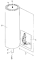
ロールアップディスプレイ16は、フレキシブルディスプレイ等の、折り曲げたり変形したりすることができる画像表示面を有する画像表示装置である。このロールアップディスプレイ16の外観を図2に斜視図で示す。
The roll-
ロールアップディスプレイ16は、回転ドラム2にその画像表示面が巻き付けられ、筒状に丸められるようになっている。回転ドラム2は、車両の前部座席と後部座席の間の天井部分に設けられている。ロールアップディスプレイ16の不使用時には、ロールアップディスプレイ16の画像表示面の全てが回転ドラム2に巻き付いた状態となっている。
The roll-up
この回転ドラム2は、モータ17によって回転軸21の周りを回転するようになっている。そして、この回転ドラム2の回転により、ロールアップディスプレイ16の画像表示面の一部が引き出され、天井から下に引き出された画像表示面が垂れ下がる。図2においては、画像表示面のうち、長さL1分に相当する部分が引き出されている。
The rotating drum 2 is rotated around a rotating
モータ17は、回転ドラム2の回転軸21付近に設けられ、CPU19からの制御信号に基づいて回転軸21を中心に回転ドラム2を回転させる。
The
ロータリーエンコーダ18は、回転ドラム2の回転軸21付近に設けられ、回転ドラム2の回転角を検出する。具体的には、ロータリーエンコーダ18は回転ドラム2が所定の角度(例えば1°)正回転または逆回転する度に、CPU19にその正回転または逆回転に応じた信号を出力する。
The
CPU19は、ROM14にあらかじめ記憶されたプログラムを実行し、そのプログラムの実行において、テレビチューナ11、入力装置15、ロータリーエンコーダ18からの信号に基づいて、ロールアップディスプレイ16、モータ17を制御する。またそのプログラムの実行において、必要に応じてRAM13、ROM14に対してデータの読み書きの制御を行う。
The
例えば、CPU19は、ユーザの入力装置15の操作によって画像表示制御装置1が起動すると、ROM14から所定のプログラムを読み出して実行することで、モータ17を制御して、ロールアップディスプレイ16の画像表示面のほぼ全体を引き出すようにする。引き出しが開始してから完了するまでの時間は、例えば30秒程度である。
For example, when the image display control device 1 is activated by the user's operation of the
また、CPU19は、入力装置15に対して電源オフの操作が行われたことを検出すると、ROM14から所定のプログラムを読み出して実行することで、モータ17を制御してロールアップディスプレイ16を回転ドラム2に完全に巻き上げ、その後に作動を停止する。
When the
またCPU19は、画像表示制御装置1の作動中、表示制御用プログラムを繰り返し実行する。図3に、この画像表示制御用プログラムのフローチャートを示す。
The
まず、ステップ110では、回転ドラム2の回転角を検出する。具体的には、ロータリーエンコーダ18からの信号に基づいて、回転ドラム2が正方向(表示面引き出し方向)に何度回転しているかを検出する。例えば、回転ドラム2が1°正回転する度にロールアップディスプレイ16から信号Aを受け、回転ドラム2が1°逆回転する度にロールアップディスプレイ16から信号Bを受ける場合、画像表示制御装置1の直近の作動開始以降の[A信号を受けた回数]−[B信号を受けた回数]が回転角度となる。
First, in step 110, the rotation angle of the rotary drum 2 is detected. Specifically, based on the signal from the
次にステップ120で、ステップ110で検出した回転角に基づいて、ロールアップディスプレイ16の画像表示面の引き出された長さを特定する。
Next, in step 120, the drawn length of the image display surface of the roll-
具体的には、ROM14にあらかじめ記憶された回転角と引き出し長さとの対応表を読み出し、この対応表に基づいて、当該回転角から引き出し長さを特定する。
Specifically, a correspondence table between the rotation angle and the drawer length stored in advance in the
対応表は、実験等によって回転ドラム2の回転角とロールアップディスプレイ16の表示面の引き出し長さとの対応をあらかじめ確認し、その確認の結果得た、回転角と引き出し長さとの1対1関係の離散的データである。ステップ120では、この対応表を用いて補間することにより、現時点の回転角から現時点の引き出し長さを計算する。
The correspondence table confirms in advance the correspondence between the rotation angle of the rotating drum 2 and the drawing length of the display surface of the roll-
他の方法としては、例えば回転角度に回転ドラム2の直径×円周率を乗算して引き出し長さを特定する方法を採用してもよい。 As another method, for example, a method of specifying the pull-out length by multiplying the rotation angle by the diameter of the rotating drum 2 × circumferential ratio may be employed.
なお、対応表は、回転角と引き出し長さとの対応を示すものでなくともよく、例えば、
[正回転を示す信号を受けた回数]−[逆回転を示す信号を受けた回数]と引き出し長さとの対応を示すものであってもよい。
Note that the correspondence table does not have to indicate the correspondence between the rotation angle and the drawer length.
It may indicate the correspondence between [number of times of receiving a signal indicating normal rotation]-[number of times of receiving a signal indicating reverse rotation] and a drawing length.
次にステップ130で、画面サイズの最適化計算を行う。すなわち、ステップ120で特定した引き出し長さに比例した画像表示範囲の長さを算出する。
Next, at
具体的には、完全な状態、すなわち引き出しが完了したときの画像表示面の引き出し長さをL0とし、ステップ120で特定した現時点の引き出し長さの値をL1とすると、L1とL0の比L1/L0を算出する。そして、ロールアップディスプレイ16の画像表示面全体の縦方向(引き出し方向)の画素数および横方向(引き出し方向に垂直な方向)の画素数のそれぞれにこの比を乗算し、その結果の値をそれぞれ画面表示範囲の縦の画素数および横の画素数とする。
Specifically, when the drawing length of the image display surface when the drawing is completed is L0, and the current drawing length value specified in step 120 is L1, the ratio L1 between L1 and L0 is L1. / L0 is calculated. Then, the ratio of the number of pixels in the vertical direction (drawing direction) and the number of pixels in the horizontal direction (direction perpendicular to the drawing direction) of the entire image display surface of the roll-up
なお、この表示範囲の表示位置が画像表示面の引き出し部分となるよう、画面表示範囲の位置は、表示画像の左下端がロールアップディスプレイ16の画像表示面のユーザから(所定のわずかなマージンを残して)向かって左下端に配されるように計算する。 Note that the position of the screen display range is determined so that the lower left corner of the display image is from the user of the image display surface of the roll-up display 16 (with a predetermined slight margin) so that the display position of the display range becomes a drawing portion of the image display surface. (Leave) and calculate to be placed at the lower left corner.
このような計算により、ロールアップディスプレイ16の画像表示面のどの位置で表示が行われるかが決まる。
Such calculation determines at which position on the image display surface of the roll-up
次にステップ150で、画像処理を行う。具体的には、テレビチューナ11から受けた映像が、ステップ140で算出した画像表示範囲に収まるように縮小(または拡大)変換を行う。
Next, in
この変換は、表示画像がステップ130で算出した画像表示範囲の大きさと同じになるよう、表示画像の縮尺を当該表示画像内で一律に変更することで行う。例えば、テレビチューナ11から受けた映像の画素数が縦720×横400であり、画像表示範囲の画素数が縦360×横200である場合、当該映像のすべての部分を一律に縦横の縮尺1/2で変換する。このように、表示画像の縮尺を当該表示画像内で一律に変更することにより、表示画像の大きさが変更されても画像の歪みが少なく済む。
This conversion is performed by uniformly changing the scale of the display image in the display image so that the display image becomes the same as the size of the image display range calculated in
なお、縮小変換におけるデータの間引き、拡大変換におけるデータの補完等は、画面表示がスムースになるよう、色や輝度の補間等を行うことによって実現する。 Note that data thinning in the reduction conversion, data complementation in the enlargement conversion, and the like are realized by performing color and luminance interpolation so that the screen display is smooth.
続いてステップ150で、ロールアップディスプレイ16を制御し、ステップ140で変換された画像を、ステップ130で算出されたロールアップディスプレイ16の画面表示範囲に表示させる。
Subsequently, in
以上のようなCPU19の作動により、画像表示制御装置1は、検出した回転ドラム2の回転角に基づいて、回転ドラム2に巻き付けられた画像表示面の引き出し長さを特定し(ステップ120)、特定した引き出し長さに収まるように画像表示範囲の大きさを算出し(ステップ130)、算出した画像表示範囲の大きさで、すなわち引き出し長さに応じて画像を縮小・拡大することにより、前記画像表示面の引き出し部分に表示させる(ステップ150)ので、表示画像が引き出された部分に収まるようになる。
By the operation of the
このような画像表示制御装置1の作動により、画像表示面の引き出し長さがL1である図2においては、テレビチューナ11からの入力映像がL1/L0に縦横が縮小された結果の表示画像31が表示される。
As a result of such an operation of the image display control device 1, in FIG. 2 in which the drawing length of the image display surface is L 1, a
また、図4のように、画像表示面の引き出し長さがL1より大きいL2である場合においては、テレビチューナ11からの入力映像がL2/L0に縦横が縮小された結果の表示画像31が表示される。
In addition, as shown in FIG. 4, when the drawing length of the image display surface is L2, which is larger than L1, a
なお、上記した実施形態においては、回転ドラム2が回転体に相当する。 In the above-described embodiment, the rotating drum 2 corresponds to a rotating body.
また、ロールアップディスプレイ16が画像表示装置に相当する。
The roll-up
また、CPU19が図3のステップ110を実行することにより、検出手段として機能する。
Further, the
また、CPU19が図3のステップ120を実行することにより、特定手段として機能する。
Further, the
また、CPU19が図3のステップ130を実行することにより、算出手段として機能する。
Further, the
また、CPU19が図3のステップ140およびステップ150を実行することにより、表示制御手段として機能する。
Further, the
なお、上記した実施形態では、回転ドアラム2の回転角をロータリーエンコーダ18によって検出しているが、モータ17をステッピングモータとし、CPU19からのモータ制御パルスの送信回数にも基づいて回転ドラム2の回転角を算出するようになっていてもよい。
In the embodiment described above, the rotation angle of the rotary door ram 2 is detected by the
また、上記した実施形態では、ロールアップディスプレイ16の画像表示面は回転ドラム2に巻き付いているが、ロールアップディスプレイ16の画像表示面は必ずしも何かに巻き付いている必要はない。例えば、ロールアップディスプレイ16の画像表示面の左右の端に、他の力を加えないと丸まるような形状のワイヤを取り付けることで、画像表示面が筒状に丸められていてもよい。
In the above-described embodiment, the image display surface of the roll-up
この場合、例えば、画像表示面の側端に、引き出し方向に沿って等間隔で穴等が設けられ、その穴を検出するセンサが当該側端に設けられ、そのセンサが検出した穴の数に基づいて、画像表示面の引き出し長さが検出されるようになっていてもよい。 In this case, for example, holes are provided at the side edges of the image display surface at equal intervals along the pull-out direction, and sensors for detecting the holes are provided at the side edges, and the number of holes detected by the sensors is determined. Based on this, the drawing length of the image display surface may be detected.
また、上記した実施形態においては、回転ドラム2の回転によってロールアップディスプレイ16の引き出し長さを算出しているが、必ずしもこのようになっておらずともよい。例えば、表示画面を挟み込むようにして、巻き取りや引き出しの際のたるみやゆがみを防止するガイドの役割をする円形のローラーをロールアップディスプレイ16の引き出し部分に設け、そのローラーの回転角をロータリーエンコーダ等によって検出し、その検出した回転角に基づいてロールアップディスプレイ16の引き出し長さを検出してもよい。
Further, in the above-described embodiment, the pull-out length of the roll-up
また、上記した実施形態では、ロールアップディスプレイ16の画像表示面はモータ17で引き出し、巻き取りが行われているが、引き出し、巻き取りは人の手作業で行うようになっていてもよい。
In the above-described embodiment, the image display surface of the roll-up
また、上記した実施形態において、ユーザが入力装置15を操作して引き出し長さを指定することで、CPU19は、モータ17を制御し、引き出し長さをその指定の長さに調整するようになっていてもよい。このとき、表示制御用プログラムは、当該調整の結果回転した回転ドラムによる引き出し長さに収まるように、画像表示範囲の大きさを算出するようになっていてもよい。
In the above-described embodiment, when the user operates the
また、上記した実施形態においては、フレキシブルディスプレイ16は、テレビ映像を表示するようになっているが、例えばカーナビゲーション装置が特定した目的地までの案内経路や地図を表示するようになっていてもよい。
In the above-described embodiment, the
また、上記した実施形態においては、画像の表示位置が画像表示面の引き出し部分の左下端に(所定のマージンを残して)詰められるようになっているが、詰める方向は、中央下端、右下端であってもよい。 In the above-described embodiment, the display position of the image is arranged at the lower left end of the drawing portion of the image display surface (with a predetermined margin). It may be.
1…画像表示制御装置、2…回転ドラム、11…テレビチューナ、12…アンテナ、
13…RAM、14…ROM、15…入力装置、16…ロールアップディスプレイ、
17…モータ、18…ロータリーエンコーダ、19…CPU、21…回転軸、
31、32…表示画像。
DESCRIPTION OF SYMBOLS 1 ... Image display control apparatus, 2 ... Rotating drum, 11 ... Television tuner, 12 ... Antenna,
13 ... RAM, 14 ... ROM, 15 ... input device, 16 ... roll-up display,
17 ... motor, 18 ... rotary encoder, 19 ... CPU, 21 ... rotary shaft,
31, 32 ... Display images.
Claims (5)
前記回転体に画像表示面が巻き付けられた画像表示装置と、
前記回転体の回転角を検出する検出手段と、
前記検出手段の検出した回転角に基づいて、前記画像表示面の引き出し長さを特定する特定手段と、
前記特定手段が特定した引き出し長さに基づいて画像表示範囲の大きさを算出する算出手段と、
前記算出手段が算出した画像表示範囲の大きさで、画像を前記画像表示面の引き出し部分に表示させる表示制御手段と、を備えた画像表示制御装置。 A rotating body that rotates around an axis;
An image display device in which an image display surface is wound around the rotating body;
Detecting means for detecting a rotation angle of the rotating body;
A specifying unit that specifies a drawing length of the image display surface based on the rotation angle detected by the detecting unit;
Calculating means for calculating the size of the image display range based on the drawer length specified by the specifying means;
An image display control device comprising: display control means for displaying an image on the drawer portion of the image display surface with the size of the image display range calculated by the calculation means.
前記画像表示面の丸められた状態から引き出された部分の長さを特定する特定手段と、
前記特定手段が特定した引き出し長さに基づいて画像表示範囲の大きさを算出する算出手段と、
前記算出手段が算出した画像表示範囲の大きさで、画像を前記画像表示面の引き出し部分に表示させる表示制御手段と、を備えた画像表示制御装置。 An image display device in which the image display surface is rolled into a cylindrical shape;
A specifying means for specifying a length of a portion drawn from the rounded state of the image display surface;
Calculating means for calculating the size of the image display range based on the drawer length specified by the specifying means;
An image display control device comprising: display control means for displaying an image on the drawer portion of the image display surface with the size of the image display range calculated by the calculation means.
Priority Applications (1)
| Application Number | Priority Date | Filing Date | Title |
|---|---|---|---|
| JP2004141077A JP2005321702A (en) | 2004-05-11 | 2004-05-11 | Image display control device |
Applications Claiming Priority (1)
| Application Number | Priority Date | Filing Date | Title |
|---|---|---|---|
| JP2004141077A JP2005321702A (en) | 2004-05-11 | 2004-05-11 | Image display control device |
Publications (1)
| Publication Number | Publication Date |
|---|---|
| JP2005321702A true JP2005321702A (en) | 2005-11-17 |
Family
ID=35469026
Family Applications (1)
| Application Number | Title | Priority Date | Filing Date |
|---|---|---|---|
| JP2004141077A Withdrawn JP2005321702A (en) | 2004-05-11 | 2004-05-11 | Image display control device |
Country Status (1)
| Country | Link |
|---|---|
| JP (1) | JP2005321702A (en) |
Cited By (18)
| Publication number | Priority date | Publication date | Assignee | Title |
|---|---|---|---|---|
| WO2007077649A1 (en) * | 2006-01-06 | 2007-07-12 | Sharp Kabushiki Kaisha | Mobile terminal device, display method, display program, and recording medium |
| WO2008062532A1 (en) * | 2006-11-24 | 2008-05-29 | Pioneer Corporation | Display device, display method, display program, and computer readable recording medium |
| JP2012527012A (en) * | 2009-05-11 | 2012-11-01 | エンパイア テクノロジー ディベロップメント エルエルシー | Folding mobile display |
| JP2013037330A (en) * | 2011-08-10 | 2013-02-21 | Samsung Display Co Ltd | Display device |
| JP2013232214A (en) * | 2007-03-06 | 2013-11-14 | Creator Technology Bv | Display device, display method and computer program product |
| JP2013242530A (en) * | 2012-05-22 | 2013-12-05 | Samsung Display Co Ltd | Display device |
| WO2015015788A1 (en) * | 2013-07-27 | 2015-02-05 | Sharp Kabushiki Kaisha | Display and method for displaying image |
| JP2015232901A (en) * | 2009-07-10 | 2015-12-24 | ルール・フェルテハールRoel VERTEGAAL | Interaction techniques for multiple flexible displays |
| WO2016020808A1 (en) * | 2014-08-07 | 2016-02-11 | 株式会社半導体エネルギー研究所 | Display device and driving assistance system |
| JP2018503866A (en) * | 2014-12-25 | 2018-02-08 | シェンジェン ロイオル テクノロジーズ カンパニー リミテッドShenzhen Royole Technologies Co., Ltd. | Flexible display device |
| JP2018084790A (en) * | 2016-11-17 | 2018-05-31 | 富士ゼロックス株式会社 | Terminal device and program |
| EP3451324A4 (en) * | 2016-06-01 | 2019-03-06 | NTT Docomo, Inc. | MOBILE TERMINAL |
| JP2021043276A (en) * | 2019-09-09 | 2021-03-18 | 株式会社デンソー | Display device |
| CN112614869A (en) * | 2019-10-04 | 2021-04-06 | 三星显示有限公司 | Display device and electronic device including the same |
| WO2021132757A1 (en) * | 2019-12-26 | 2021-07-01 | 엘지전자 주식회사 | Display apparatus |
| JP2022169030A (en) * | 2021-04-27 | 2022-11-09 | アルプスアルパイン株式会社 | electronic device |
| US11705060B2 (en) | 2020-12-04 | 2023-07-18 | Samsung Electronics Co., Ltd. | Electronic device and method for predicting residual image of display and compensating for residual image of the display |
| US12175903B2 (en) | 2020-03-09 | 2024-12-24 | Samsung Electronics Co., Ltd. | Electronic device including display and method for measuring movement distance of display |
-
2004
- 2004-05-11 JP JP2004141077A patent/JP2005321702A/en not_active Withdrawn
Cited By (39)
| Publication number | Priority date | Publication date | Assignee | Title |
|---|---|---|---|---|
| JPWO2007077649A1 (en) * | 2006-01-06 | 2009-06-04 | シャープ株式会社 | Portable terminal device, display method, display program, and recording medium |
| JP2011034087A (en) * | 2006-01-06 | 2011-02-17 | Sharp Corp | Mobile terminal device, display method, display program, and recording medium |
| US8174628B2 (en) | 2006-01-06 | 2012-05-08 | Sharp Kabushiki Kaisha | Mobile terminal unit, display method, display program, and recording medium |
| WO2007077649A1 (en) * | 2006-01-06 | 2007-07-12 | Sharp Kabushiki Kaisha | Mobile terminal device, display method, display program, and recording medium |
| WO2008062532A1 (en) * | 2006-11-24 | 2008-05-29 | Pioneer Corporation | Display device, display method, display program, and computer readable recording medium |
| JPWO2008062532A1 (en) * | 2006-11-24 | 2010-03-04 | パイオニア株式会社 | Display device, display method, display program, and computer-readable recording medium |
| JP2013232214A (en) * | 2007-03-06 | 2013-11-14 | Creator Technology Bv | Display device, display method and computer program product |
| JP2012527012A (en) * | 2009-05-11 | 2012-11-01 | エンパイア テクノロジー ディベロップメント エルエルシー | Folding mobile display |
| JP2015232901A (en) * | 2009-07-10 | 2015-12-24 | ルール・フェルテハールRoel VERTEGAAL | Interaction techniques for multiple flexible displays |
| JP2013037330A (en) * | 2011-08-10 | 2013-02-21 | Samsung Display Co Ltd | Display device |
| US9230468B2 (en) | 2011-08-10 | 2016-01-05 | Samsung Display Co., Ltd. | Display device |
| JP2013242530A (en) * | 2012-05-22 | 2013-12-05 | Samsung Display Co Ltd | Display device |
| WO2015015788A1 (en) * | 2013-07-27 | 2015-02-05 | Sharp Kabushiki Kaisha | Display and method for displaying image |
| US10434847B2 (en) | 2014-08-07 | 2019-10-08 | Semiconductor Energy Laboratory Co., Ltd. | Display device and driving support system |
| US11205356B2 (en) | 2014-08-07 | 2021-12-21 | Semiconductor Energy Laboratory Co., Ltd. | Display device and driving support system |
| JPWO2016020808A1 (en) * | 2014-08-07 | 2017-07-06 | 株式会社半導体エネルギー研究所 | Display device and driving support system |
| US11837112B2 (en) | 2014-08-07 | 2023-12-05 | Semiconductor Energy Laboratory Co., Ltd. | Display device and driving support system |
| JP2023139108A (en) * | 2014-08-07 | 2023-10-03 | 株式会社半導体エネルギー研究所 | display device |
| WO2016020808A1 (en) * | 2014-08-07 | 2016-02-11 | 株式会社半導体エネルギー研究所 | Display device and driving assistance system |
| JP2020008870A (en) * | 2014-08-07 | 2020-01-16 | 株式会社半導体エネルギー研究所 | Operation supporting system |
| JP2025061594A (en) * | 2014-08-07 | 2025-04-10 | 株式会社半導体エネルギー研究所 | Driver Assistance Systems |
| US12277874B2 (en) | 2014-08-07 | 2025-04-15 | Semiconductor Energy Laboratory Co., Ltd. | Display device and driving support system |
| JP2018503866A (en) * | 2014-12-25 | 2018-02-08 | シェンジェン ロイオル テクノロジーズ カンパニー リミテッドShenzhen Royole Technologies Co., Ltd. | Flexible display device |
| EP3451324A4 (en) * | 2016-06-01 | 2019-03-06 | NTT Docomo, Inc. | MOBILE TERMINAL |
| JP2018084790A (en) * | 2016-11-17 | 2018-05-31 | 富士ゼロックス株式会社 | Terminal device and program |
| JP7052220B2 (en) | 2016-11-17 | 2022-04-12 | 富士フイルムビジネスイノベーション株式会社 | Terminal devices and programs |
| JP2021043276A (en) * | 2019-09-09 | 2021-03-18 | 株式会社デンソー | Display device |
| JP7255431B2 (en) | 2019-09-09 | 2023-04-11 | 株式会社デンソー | Display device |
| JP2021060570A (en) * | 2019-10-04 | 2021-04-15 | 三星ディスプレイ株式會社Samsung Display Co.,Ltd. | Display device and electronic device having the same |
| CN112614869A (en) * | 2019-10-04 | 2021-04-06 | 三星显示有限公司 | Display device and electronic device including the same |
| JP7545816B2 (en) | 2019-10-04 | 2024-09-05 | 三星ディスプレイ株式會社 | Display device |
| US12120911B2 (en) | 2019-10-04 | 2024-10-15 | Samsung Display Co., Ltd. | Display apparatus and electric apparatus including the same |
| US11978374B2 (en) | 2019-12-26 | 2024-05-07 | Lg Electronics Inc. | Display apparatus |
| WO2021132757A1 (en) * | 2019-12-26 | 2021-07-01 | 엘지전자 주식회사 | Display apparatus |
| US12175903B2 (en) | 2020-03-09 | 2024-12-24 | Samsung Electronics Co., Ltd. | Electronic device including display and method for measuring movement distance of display |
| US12046177B1 (en) | 2020-12-04 | 2024-07-23 | Samsung Electronics Co., Ltd. | Electronic device and method for predicting and compensating for residual image of display |
| US11705060B2 (en) | 2020-12-04 | 2023-07-18 | Samsung Electronics Co., Ltd. | Electronic device and method for predicting residual image of display and compensating for residual image of the display |
| JP7628367B2 (en) | 2021-04-27 | 2025-02-10 | アルプスアルパイン株式会社 | Electronics |
| JP2022169030A (en) * | 2021-04-27 | 2022-11-09 | アルプスアルパイン株式会社 | electronic device |
Similar Documents
| Publication | Publication Date | Title |
|---|---|---|
| JP2005321702A (en) | Image display control device | |
| JP3370033B2 (en) | Automatic screen rotation apparatus and method for video display equipment | |
| KR100512616B1 (en) | (An) image display device for having (a) variable screen ratio and method of controlling the same | |
| US7525514B2 (en) | Plasma display apparatus | |
| EP2228788A1 (en) | Display apparatus and control method of the same | |
| JP4259971B2 (en) | Video display device | |
| US20050270644A1 (en) | Projection screen unit with projection surfaces optimized for different ambient light levels | |
| JPWO2019111553A1 (en) | Display device | |
| JP2010175885A (en) | Video display device | |
| KR20110103167A (en) | Roll-screen unit for both television and clear display | |
| CN110568867A (en) | Control method, device and equipment of cloud deck | |
| KR20060093577A (en) | Display device and control method of display device | |
| JP2006308911A (en) | Image display control device and program for image display control device | |
| JP2003116074A (en) | Large screen high definition digital video viewing system | |
| JP2006157395A (en) | Electronic program information display control apparatus and electronic program information display control method | |
| JP2012156797A (en) | Image processing apparatus and image processing method | |
| CN102956177A (en) | Method for preventing display screen from blurring and display screen | |
| JP2008046211A (en) | Display housing system | |
| JP2013238648A (en) | Display device | |
| JP3326810B2 (en) | Television equipment | |
| JP2003244692A (en) | Video display system | |
| JP2005114902A (en) | Projection type video display device | |
| CN106851381B (en) | Display terminal information preview method and device | |
| JP2008294697A (en) | Television receiver | |
| JPH0895536A (en) | Display controller |
Legal Events
| Date | Code | Title | Description |
|---|---|---|---|
| A621 | Written request for application examination |
Free format text: JAPANESE INTERMEDIATE CODE: A621 Effective date: 20060707 |
|
| A761 | Written withdrawal of application |
Free format text: JAPANESE INTERMEDIATE CODE: A761 Effective date: 20081107 |